EP0256225A2 - Semoir - Google Patents
Semoir Download PDFInfo
- Publication number
- EP0256225A2 EP0256225A2 EP87107246A EP87107246A EP0256225A2 EP 0256225 A2 EP0256225 A2 EP 0256225A2 EP 87107246 A EP87107246 A EP 87107246A EP 87107246 A EP87107246 A EP 87107246A EP 0256225 A2 EP0256225 A2 EP 0256225A2
- Authority
- EP
- European Patent Office
- Prior art keywords
- intermediate frame
- bottom roller
- sowing machine
- crossbar
- seeder
- Prior art date
- Legal status (The legal status is an assumption and is not a legal conclusion. Google has not performed a legal analysis and makes no representation as to the accuracy of the status listed.)
- Withdrawn
Links
Images



Classifications
-
- A—HUMAN NECESSITIES
- A01—AGRICULTURE; FORESTRY; ANIMAL HUSBANDRY; HUNTING; TRAPPING; FISHING
- A01C—PLANTING; SOWING; FERTILISING
- A01C15/00—Fertiliser distributors
- A01C15/005—Undercarriages, tanks, hoppers, stirrers specially adapted for seeders or fertiliser distributors
-
- A—HUMAN NECESSITIES
- A01—AGRICULTURE; FORESTRY; ANIMAL HUSBANDRY; HUNTING; TRAPPING; FISHING
- A01B—SOIL WORKING IN AGRICULTURE OR FORESTRY; PARTS, DETAILS, OR ACCESSORIES OF AGRICULTURAL MACHINES OR IMPLEMENTS, IN GENERAL
- A01B49/00—Combined machines
- A01B49/04—Combinations of soil-working tools with non-soil-working tools, e.g. planting tools
- A01B49/06—Combinations of soil-working tools with non-soil-working tools, e.g. planting tools for sowing or fertilising
Definitions
- the invention relates to a seed drill according to the preamble of patent claim 1.
- Such a seeder is already known from DE-OS 20 01 062.
- This seeder has a frame, a storage container and coulters.
- the undercarriage of this seeder is therefore arranged under the storage container and in front of the coulters and is designed as a continuous bottom roller.
- the metering elements of the seeder are driven from this bottom roller.
- the frame of this seeder has three-point coupling elements, by means of which the seeder can be coupled to the three-point linkage of a tractor.
- This seed drill is not intended to be used in combination with a PTO-driven tillage implement.
- the invention is based on the object with the simplest means to create a universal seed drill.
- a seed drill has become known from German laid-open specification 31 05 641 which, on the one hand, can be coupled behind a PTO-driven soil cultivation implement with a trailing roller as a combination seeder and, on the other hand, can be coupled directly to the three-point linkage of a tractor via a special chassis or an intermediate frame.
- a disadvantage of this seeder is that when the seeder is used solo, it is not possible to press the seedbed, and that it is also not readily possible to use the known seeder in combination with a simple tillage implement.
- track loosening tines or track spreading elements are arranged on the intermediate frames in the area of the tractor wheels.
- the solidified soil strips originating from the tractor wheels can either be loosened or filled up with soil again by means of the track spreader elements, so that the seeds can then be deposited by the coulters of the seeder in a flat soil surface.
- the intermediate frame has at least one crossbar running transversely to the direction of travel, that the crossbar extends over the entire working width of the bottom roller, and that several soil loosening tines are arranged on this crossbar over the entire working width of the seeder.
- the intermediate frame has at least one crossbar running transversely to the direction of travel, that the crossbar extends over the entire working width of the bottom roller, and that several soil loosening tines are arranged on this crossbar over the entire working width of the seeder.
- the invention provides that the intermediate frame has three-point coupling elements on its front side.
- a particularly advantageous design of the bottom roller results is characterized in that the bottom roller consists of rubber tires arranged side by side. Because of this design of the bottom roller, it is not necessary that wipers have to be arranged on the bottom roller in order to prevent the bottom roller from becoming clogged or smeared: bottom roller, but rather a self-cleaning effect is achieved by appropriately designing the bottom roller as a rubber tire roller .
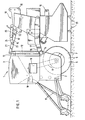
- the seed drill 1 has the frame 2, the storage container 3, the coulters 4 and the undercarriage 5.
- the undercarriage 5 is arranged below the storage container 3 and in front of the sowing elements designed as coulters and as continuous bottom roller 6 formed.
- This floor roller consists of rubber tires 7 arranged side by side.
- the metering elements 10 are driven from the floor roller 6 via the chain drive 8 and the control gear 9. Via the metering elements 10, the seed located in the storage container 3 is fed in adjustable amounts via the seed line tubes 11 to the seed coulters 4, which deposit the seed in the ground.
- a seed harrow can be arranged behind the seeder in a known and therefore not shown manner.
- the seeder 1 can be coupled behind the PTO-driven tillage implement 18 via the upper coupling rod 15 and the two lower coupling rods 16, which together form the coupling elements 17.
- the PTO-driven soil cultivation device 18 is designed as a rotary cultivator or rotary harrow.
- the PTO-driven tillage implement 18 is to be coupled via the three-point coupling elements 19 in a known and therefore not shown manner to the three-point linkage of an agricultural tractor, also not shown.
- the tillage tines 20 of the tillage implement 18 are driven in a known and therefore also not shown manner via a propeller shaft from the PTO of the agricultural tractor, not shown.
- the upper coupling rod 15 consists of the two rods 21 and 22, which are connected to one another via the joint 23.
- the lever 24 is also arranged on the joint 23. Between the lever 24 and the upper part of the three-point coupling element 19 of the Soil cultivation device 18, the hydraulic cylinder 25 is arranged. By means of the hydraulic cylinder 25, which is connected to the tractor hydraulics of the tillage implement 1 8-.
- the rods 21 and 22 of the upper coupling rod 15 can be folded or folded, so that the drill 1 is pivoted forward about the pivot axis extending through the lower coupling 14, so that the center of gravity of the drill 1 and thus the overall center of gravity of the implement combination consisting of the seed drill 1 and the tillage implement 18 is shifted in the direction of the tractor.
- the seed drill 1 can be coupled directly to the three-point linkage of the tractor, not shown, by means of the intermediate frame 26 in accordance with FIG. 2.
- the intermediate frame 26 On its rear side, the intermediate frame 26 has the two lower coupling elements 27 and the upper coupling rod 28, by means of which the intermediate frame 26 can be coupled to the upper coupling 13 and the lower coupling 14 of the coupling frame 12 of the seed drill 1 in a simple manner.
- the intermediate frame 26 has the V-shaped tube 29 and on its underside the cross tube 30.
- the intermediate frame 26 has on its front side the upper three-point coupling element 31 and the two lower three-point coupling elements 32, via which the seeder can be arranged directly on the three-point linkage of a tractor. Furthermore, on the cross pipe 30 of the intermediate frame 26, the direction indicated by dash-dot lines S and Spurzustreicher purlock mecanics institute 33 within or be positioned closely adjacent to the S chlepperspur of the sowing machine 1 towing tractor.
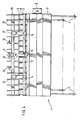
- the intermediate frame 34 which is coupled to the upper coupling elements 13 and the lower coupling elements 14 of the coupling frame 12 of the seeder 1 via the two lower coupling elements 27 and the upper coupling element 28, in turn has the upper three-point coupling element 31 and on its front side on its underside the two lower three-point coupling elements 32. Furthermore, the intermediate frame 34 has on its underside the transverse bar 36 extending transversely to the direction of travel 35.
- the crossbar 36 extends over the entire working width of the bottom roller 6 or the seeder 1.
- the loosening tines 37 are arranged on the crossbar 36 over the entire working width of the seeder 1.
- the crossbar 36 is located close to the bottom roller 6 and at a small distance A. The distance A between the crossbar 36 and the circumferential surface of the bottom roller 6 is less than 10 cm.
- the coupling elements 13, 14, 27 and 28 are located between the intermediate frame 34 and the seeder 1 essentially in the area above the bottom roller 6.
- the intermediate frame 38 according to FIG. 5, which is connected to the coupling frame 12 via the upper coupling rod 39 and the two lower coupling rods 40. Seed drill 1 is coupled, has on its front side the upper three-point coupling element 31 and the two lower three-point coupling elements 32 for connecting the intermediate frame 38 to the three-point linkage of a tractor, not shown. Furthermore, the intermediate frame 38 has on its underside the two transverse bars 41 and 42 arranged one behind the other at a distance. The soil loosening tines 37 are arranged in a row both on the front crossbar 41 and on the rear crossbar 42. So these are Soil loosening tines 37 are arranged in two transverse rows one behind the other.
- the seed drill 1 can be arranged either behind a PTO-driven soil cultivation implement 18 or by means of the intermediate frame 2 6, 34 and 38 directly on the three-point linkage of a tractor.
Landscapes
- Life Sciences & Earth Sciences (AREA)
- Soil Sciences (AREA)
- Environmental Sciences (AREA)
- Engineering & Computer Science (AREA)
- Mechanical Engineering (AREA)
- Soil Working Implements (AREA)
- Sowing (AREA)
Applications Claiming Priority (2)
| Application Number | Priority Date | Filing Date | Title |
|---|---|---|---|
| DE3618200 | 1986-05-30 | ||
| DE19863618200 DE3618200A1 (de) | 1986-05-30 | 1986-05-30 | Saemaschine |
Publications (2)
| Publication Number | Publication Date |
|---|---|
| EP0256225A2 true EP0256225A2 (fr) | 1988-02-24 |
| EP0256225A3 EP0256225A3 (fr) | 1988-12-28 |
Family
ID=6301938
Family Applications (1)
| Application Number | Title | Priority Date | Filing Date |
|---|---|---|---|
| EP87107246A Withdrawn EP0256225A3 (fr) | 1986-05-30 | 1987-05-19 | Semoir |
Country Status (3)
| Country | Link |
|---|---|
| EP (1) | EP0256225A3 (fr) |
| DE (1) | DE3618200A1 (fr) |
| DK (1) | DK277987A (fr) |
Cited By (1)
| Publication number | Priority date | Publication date | Assignee | Title |
|---|---|---|---|---|
| US10053745B2 (en) | 2010-01-19 | 2018-08-21 | Renmatix, Inc. | Production of fermentable sugars and lignin from biomass using supercritical fluids |
Family Cites Families (6)
| Publication number | Priority date | Publication date | Assignee | Title |
|---|---|---|---|---|
| DE2001062A1 (de) * | 1970-01-12 | 1971-07-22 | Eicher Traktor Landmasch | Drillmaschine |
| DE3033848A1 (de) * | 1980-09-09 | 1982-03-18 | Rabewerk Heinrich Clausing, 4515 Bad Essen | Kombinationsgeraet fuer die bodenbearbeitung |
| DE3105641A1 (de) * | 1981-02-17 | 1982-09-02 | Amazonen-Werke H. Dreyer Gmbh & Co Kg, 4507 Hasbergen | "drillmaschine" |
| DE3206012A1 (de) * | 1982-02-19 | 1983-09-01 | Amazonen-Werke H. Dreyer Gmbh & Co Kg, 4507 Hasbergen | An einem schlepper anbaubare landwirtschaftliche geraetekombination |
| NL191167B (nl) * | 1982-12-06 | 1994-10-03 | Lely Nv C Van Der | Samenstel van een rol en een zaaimachine. |
| NL8402020A (nl) * | 1984-06-27 | 1986-01-16 | Lely Nv C Van Der | Grondbewerkingsmachine, in het bijzonder geschikt voor de bereiding van een zaaibed. |
-
1986
- 1986-05-30 DE DE19863618200 patent/DE3618200A1/de not_active Withdrawn
-
1987
- 1987-05-19 EP EP87107246A patent/EP0256225A3/fr not_active Withdrawn
- 1987-05-29 DK DK277987A patent/DK277987A/da not_active Application Discontinuation
Cited By (1)
| Publication number | Priority date | Publication date | Assignee | Title |
|---|---|---|---|---|
| US10053745B2 (en) | 2010-01-19 | 2018-08-21 | Renmatix, Inc. | Production of fermentable sugars and lignin from biomass using supercritical fluids |
Also Published As
| Publication number | Publication date |
|---|---|
| DE3618200A1 (de) | 1987-12-03 |
| DK277987A (da) | 1987-12-01 |
| EP0256225A3 (fr) | 1988-12-28 |
| DK277987D0 (da) | 1987-05-29 |
Similar Documents
| Publication | Publication Date | Title |
|---|---|---|
| DE3128709A1 (de) | Schichtengrubber mit den arbeitswerkzeugen zugeordneter anpresswalze | |
| EP0365049B1 (fr) | Machine combinée | |
| EP0172358B1 (fr) | Machine combinée pour l'ameublissement du sol et la préparation d'un lit de semence | |
| DE69325166T2 (de) | Kombination eines drehpfluges und eines gerätes zur saatbettbereitung | |
| DE3105641C2 (fr) | ||
| DE3447099A1 (de) | Anbaugeraetekombination fuer traktoren zur bodenbearbeitung und saatbettherrichtung | |
| DE102012004517A1 (de) | Bodenbearbeitungsgerät | |
| DE2528930A1 (de) | Tragrahmen fuer landwirtschaftliche maschinen und geraete | |
| EP0445582B1 (fr) | Machine pour travailler le sol | |
| DE8707011U1 (de) | Sämaschine | |
| DE3214897C1 (de) | Saemaschine | |
| DE3633540A1 (de) | Landwirtschaftliche geraetekombination | |
| EP0256225A2 (fr) | Semoir | |
| DE3609968A1 (de) | Saatwalzenpflug | |
| EP0327869A1 (fr) | Machine combinée de culture et de semis | |
| DE3105640A1 (de) | "geraetekombination fuer die landwirtschaft" | |
| DE3235959A1 (de) | Verfahren und vorrichtung zur bodenlockerung, saatbettherrichtung und bestellung mit traktoren und arbeitsgeraeten | |
| DE3306804A1 (de) | Saemaschine | |
| EP0223133B1 (fr) | Semoir | |
| DE202021101060U1 (de) | Bodenbearbeitungsmaschine | |
| DE4013531A1 (de) | Einzelkornsaegeraet | |
| EP0216003A2 (fr) | Méthode et disposition d'outils pour le travail du sol, la préparation du lit de semence et l'enfouissement des semences | |
| DE3734194A1 (de) | Landwirtschaftliche bestellkombination | |
| EP0752202A2 (fr) | Bâti de support pour machine agricole de travail du sol et/ou semence | |
| DE4015736A1 (de) | Landwirtschaftliche geraetekombination |
Legal Events
| Date | Code | Title | Description |
|---|---|---|---|
| PUAI | Public reference made under article 153(3) epc to a published international application that has entered the european phase |
Free format text: ORIGINAL CODE: 0009012 |
|
| AK | Designated contracting states |
Kind code of ref document: A2 Designated state(s): AT DE FR GB NL |
|
| PUAL | Search report despatched |
Free format text: ORIGINAL CODE: 0009013 |
|
| AK | Designated contracting states |
Kind code of ref document: A3 Designated state(s): AT DE FR GB NL |
|
| STAA | Information on the status of an ep patent application or granted ep patent |
Free format text: STATUS: THE APPLICATION IS DEEMED TO BE WITHDRAWN |
|
| 18D | Application deemed to be withdrawn |
Effective date: 19890629 |
|
| RIN1 | Information on inventor provided before grant (corrected) |
Inventor name: GATTERMANN, BERND Inventor name: STEENKEN, BERHARD |