EP0256288A2 - Méthode et dispositif de traitement d'un signal en fonction de la fréquence - Google Patents
Méthode et dispositif de traitement d'un signal en fonction de la fréquence Download PDFInfo
- Publication number
- EP0256288A2 EP0256288A2 EP87109773A EP87109773A EP0256288A2 EP 0256288 A2 EP0256288 A2 EP 0256288A2 EP 87109773 A EP87109773 A EP 87109773A EP 87109773 A EP87109773 A EP 87109773A EP 0256288 A2 EP0256288 A2 EP 0256288A2
- Authority
- EP
- European Patent Office
- Prior art keywords
- signal
- frequency
- filters
- pass
- filter
- Prior art date
- Legal status (The legal status is an assumption and is not a legal conclusion. Google has not performed a legal analysis and makes no representation as to the accuracy of the status listed.)
- Ceased
Links
Images
Classifications
-
- H—ELECTRICITY
- H03—ELECTRONIC CIRCUITRY
- H03H—IMPEDANCE NETWORKS, e.g. RESONANT CIRCUITS; RESONATORS
- H03H17/00—Networks using digital techniques
- H03H17/02—Frequency selective networks
- H03H17/06—Non-recursive filters
Definitions
- the invention is based on a method according to the preamble of the main claim.
- the method according to the invention with the characterizing features of the main claim has the advantage in a realization with a signal processor that the number of computing and storage processes it is small that relatively complex filter arrangements can be implemented with available signal processors.
- a largely arbitrary, particularly advantageous division into subbands is possible, in particular those with constant relative bandwidth.
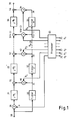
- FIGS. 1 and 3 can be regarded as flow diagrams for programs stored in a signal processor or as block diagrams of a circuit implementation.
- the input of the first filter 11 is connected to the input 10 of the filter arrangement, while the input of the first all-pass 21 is connected to the input 10 via a multiplier 20.
- the outputs 31, 32 ... 3n of the filters 11, 12 ... 1n are connected on the one hand to the input of the following filter and on the other hand to the input of a multiplier 41, 42 ... 4 (n-1), 4n.
- the output signals of the multipliers are added in adders 51, 52 ... 5 (n-1), 5n to the output signals of the respective all-passes 21, 22 ... 2n.
- the output of the last adder 5n forms the output 30 of the entire arrangement.
- the multipliers 20, 41, 42 ... 4 (n-1), 4n are supplied by a processor 60 factors a, b1, b2 ... b (n-1), b n , which consist of control values s0 to s n be determined.
- the control values each represent a transmission factor or signals to be set for a frequency range, from which the transmission factors are obtained by means of calculations, and are fed to the inputs 70 and 71 to 7n of the processor 60.
- the factors can be determined for the other frequency ranges, whereupon the transmission factors can be set largely independently of one another with sufficient adjacent channel attenuation for the individual frequency ranges by linear superimposition.
- the arrangement according to the invention can, as in connection with Figures 1 and 2 explained, can be realized with low-pass filters. However, high-pass filters can also be used, the cut-off frequency of which increases from time to time.
- the exemplary embodiment explained in connection with FIG. 1 can be used in many ways.
- a preferred application is the equalization of audio signals which are taken from a magnetic tape.
- the division of the entire frequency band into subbands of the same relative bandwidth selected in the exemplary embodiment is particularly advantageous.
- the control variables s0 to s n can be set manually or called up from a memory, for example as a preset equalization characteristic. It is also possible to derive the control variables from a signal supplied to the arrangement, as a result of which an adaptive behavior of the arrangement is achieved.
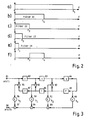
- FIG. 3 shows a linear-phase transversal filter in more detail, as can be used advantageously in the arrangement according to FIG. 1.
- the digital signal x (kT) to be filtered is fed to the input 81.
- T means the sampling period and k the respective ordinal number of the sampling period.
- the input signal is delayed 2N times by one sampling period T. For better over only delays 82, 83, 84, 85, 86, 87 are shown. In digital circuits, such delays can be easily implemented using clocked registers.
- the undelayed input signal x (kT) and the input signal delayed by T to 2NT are each evaluated with different coefficients, which determine the filter characteristic, and subsequently combined to form the output signal y (kT).
- the even number of delays results in a signal delayed by an average time between delays 84 and 85, which signal is evaluated with the coefficient h N by means of a multiplier 88 and fed to adder 89.
- the signals delayed by n sampling periods and n sampling periods more are combined in an adder, evaluated in a multiplier with the coefficient h (N-n) and added to the output signal via an adder.
- adders 90, 92, 95, multipliers 91, 93, 96 and adders 89, 94, 97 1 ... N.
- the output signal y (kT) is available at output 28. Filters described in connection with FIG. 3 are known per se and are described for example in Lücker, Raimund: Fundamentals of Digital Filters.
- the multipliers 41 to 4n can also be replaced by multiplying the coefficients h0 to h N by the factor b 1, b 2 or b n provided for the respective filter and the resulting products to the multipliers 96, 93, 91, 88 (Fig. 3) are supplied.
Landscapes
- Physics & Mathematics (AREA)
- Engineering & Computer Science (AREA)
- Computer Hardware Design (AREA)
- Mathematical Physics (AREA)
- Complex Calculations (AREA)
- Stabilization Of Oscillater, Synchronisation, Frequency Synthesizers (AREA)
- Stereo-Broadcasting Methods (AREA)
- Filters That Use Time-Delay Elements (AREA)
Applications Claiming Priority (2)
| Application Number | Priority Date | Filing Date | Title |
|---|---|---|---|
| DE3627677 | 1986-08-14 | ||
| DE19863627677 DE3627677A1 (de) | 1986-08-14 | 1986-08-14 | Verfahren und anordnung zur frequenzabhaengigen beeinflussung eines signals |
Publications (2)
| Publication Number | Publication Date |
|---|---|
| EP0256288A2 true EP0256288A2 (fr) | 1988-02-24 |
| EP0256288A3 EP0256288A3 (fr) | 1989-07-12 |
Family
ID=6307430
Family Applications (1)
| Application Number | Title | Priority Date | Filing Date |
|---|---|---|---|
| EP87109773A Ceased EP0256288A3 (fr) | 1986-08-14 | 1987-07-07 | Méthode et dispositif de traitement d'un signal en fonction de la fréquence |
Country Status (2)
| Country | Link |
|---|---|
| EP (1) | EP0256288A3 (fr) |
| DE (1) | DE3627677A1 (fr) |
Cited By (1)
| Publication number | Priority date | Publication date | Assignee | Title |
|---|---|---|---|---|
| US5262972A (en) * | 1991-07-17 | 1993-11-16 | Hughes Missile Systems Company | Multichannel digital filter apparatus and method |
Families Citing this family (1)
| Publication number | Priority date | Publication date | Assignee | Title |
|---|---|---|---|---|
| US5173924A (en) * | 1990-05-21 | 1992-12-22 | Sony Corporation | Method for equalizing received burst signal |
Family Cites Families (2)
| Publication number | Priority date | Publication date | Assignee | Title |
|---|---|---|---|---|
| US2711516A (en) * | 1949-10-29 | 1955-06-21 | Rca Corp | Frequency discriminatory systems |
| DE2810504A1 (de) * | 1978-03-10 | 1979-09-13 | Siemens Ag | Schaltungsanordnung zur automatischen entzerrung eines signals |
-
1986
- 1986-08-14 DE DE19863627677 patent/DE3627677A1/de not_active Withdrawn
-
1987
- 1987-07-07 EP EP87109773A patent/EP0256288A3/fr not_active Ceased
Cited By (1)
| Publication number | Priority date | Publication date | Assignee | Title |
|---|---|---|---|---|
| US5262972A (en) * | 1991-07-17 | 1993-11-16 | Hughes Missile Systems Company | Multichannel digital filter apparatus and method |
Also Published As
| Publication number | Publication date |
|---|---|
| EP0256288A3 (fr) | 1989-07-12 |
| DE3627677A1 (de) | 1988-02-25 |
Similar Documents
| Publication | Publication Date | Title |
|---|---|---|
| DE68905246T2 (de) | Adaptives, digitales filter mit einem nicht rekursiven teil und einem rekursiven teil. | |
| EP0889588B1 (fr) | Combinaison de filtres pour la conversion de la fréquence d'échantillonnage | |
| DE69332975T2 (de) | Digitales filter mit hoher genauigkeit und effizienz | |
| DE3044208C2 (de) | Interpolator zur Erhöhung der Wortgeschwindigkeit eines digitalen Signals | |
| DE69125349T2 (de) | Einstellungsverfahren für Einrichtungen zur Auslöschung Signalzerstreuungen in Nachrichtenübertragungssystemen | |
| DE3510660C2 (fr) | ||
| DE3333984C2 (fr) | ||
| DE69020488T2 (de) | Schallfeld-Steuerungssystem. | |
| EP0758817B1 (fr) | Egaliseur pour signaux numériques | |
| DE3918866A1 (de) | Anordnung zur umsetzung eines signals mit einer ersten abtastrate in ein signal mit einer zweiten abtastrate | |
| DE69613203T2 (de) | Schaltung zur digitalen Nyquistfilterung von Zwischenfrequenzsignalen | |
| DE3121310C2 (fr) | ||
| DE68920349T2 (de) | Anordnung zur Auslöschung von Geisterbildern. | |
| DE2839229C2 (de) | Frequenzweiche mit einem Transversalfilter | |
| DE4026476C2 (de) | Komplexes Polyphasennetzwerk | |
| DE4332735C2 (de) | Verfahren zum digitalen Erzeugen eines komplexen Basisbandsignals | |
| DE3922469C2 (fr) | ||
| EP0256286B1 (fr) | Dispositif de filtrage | |
| DE69121986T2 (de) | Eingangsgewichteter Transversalfilter | |
| DE3627677A1 (de) | Verfahren und anordnung zur frequenzabhaengigen beeinflussung eines signals | |
| DE3702215A1 (de) | Uebertragungsanordnung fuer digitale signale | |
| EP0258574A2 (fr) | Dispositif de filtrage | |
| DE3047450C2 (de) | Filter zur Änderung der Abtastfrequenz | |
| DE69223166T2 (de) | Eingangs-gewichtetes Transversalfilter | |
| DE3916256C2 (fr) |
Legal Events
| Date | Code | Title | Description |
|---|---|---|---|
| PUAI | Public reference made under article 153(3) epc to a published international application that has entered the european phase |
Free format text: ORIGINAL CODE: 0009012 |
|
| AK | Designated contracting states |
Kind code of ref document: A2 Designated state(s): DE FR GB IT SE |
|
| PUAL | Search report despatched |
Free format text: ORIGINAL CODE: 0009013 |
|
| AK | Designated contracting states |
Kind code of ref document: A3 Designated state(s): DE FR GB IT SE |
|
| 17P | Request for examination filed |
Effective date: 19890710 |
|
| 17Q | First examination report despatched |
Effective date: 19910731 |
|
| STAA | Information on the status of an ep patent application or granted ep patent |
Free format text: STATUS: THE APPLICATION HAS BEEN REFUSED |
|
| 18R | Application refused |
Effective date: 19930718 |
|
| RIN1 | Information on inventor provided before grant (corrected) |
Inventor name: VOGELSANG, ULRICH, DR.ING. |