EP0256376A2 - Bras de charnière pour une charnière de meuble - Google Patents
Bras de charnière pour une charnière de meuble Download PDFInfo
- Publication number
- EP0256376A2 EP0256376A2 EP87110986A EP87110986A EP0256376A2 EP 0256376 A2 EP0256376 A2 EP 0256376A2 EP 87110986 A EP87110986 A EP 87110986A EP 87110986 A EP87110986 A EP 87110986A EP 0256376 A2 EP0256376 A2 EP 0256376A2
- Authority
- EP
- European Patent Office
- Prior art keywords
- hook
- hinge arm
- plate
- base plate
- extensions
- Prior art date
- Legal status (The legal status is an assumption and is not a legal conclusion. Google has not performed a legal analysis and makes no representation as to the accuracy of the status listed.)
- Granted
Links
Images

Classifications
-
- E—FIXED CONSTRUCTIONS
- E05—LOCKS; KEYS; WINDOW OR DOOR FITTINGS; SAFES
- E05D—HINGES OR SUSPENSION DEVICES FOR DOORS, WINDOWS OR WINGS
- E05D7/00—Hinges or pivots of special construction
- E05D7/12—Hinges or pivots of special construction to allow easy detachment of the hinge from the wing or the frame
- E05D7/123—Hinges or pivots of special construction to allow easy detachment of the hinge from the wing or the frame specially adapted for cabinets or furniture
- E05D7/125—Hinges or pivots of special construction to allow easy detachment of the hinge from the wing or the frame specially adapted for cabinets or furniture the hinge having two or more pins
-
- E—FIXED CONSTRUCTIONS
- E05—LOCKS; KEYS; WINDOW OR DOOR FITTINGS; SAFES
- E05D—HINGES OR SUSPENSION DEVICES FOR DOORS, WINDOWS OR WINGS
- E05D7/00—Hinges or pivots of special construction
- E05D7/04—Hinges adjustable relative to the wing or the frame
- E05D7/0407—Hinges adjustable relative to the wing or the frame the hinges having two or more pins and being specially adapted for cabinets or furniture
-
- E—FIXED CONSTRUCTIONS
- E05—LOCKS; KEYS; WINDOW OR DOOR FITTINGS; SAFES
- E05Y—INDEXING SCHEME ASSOCIATED WITH SUBCLASSES E05D AND E05F, RELATING TO CONSTRUCTION ELEMENTS, ELECTRIC CONTROL, POWER SUPPLY, POWER SIGNAL OR TRANSMISSION, USER INTERFACES, MOUNTING OR COUPLING, DETAILS, ACCESSORIES, AUXILIARY OPERATIONS NOT OTHERWISE PROVIDED FOR, APPLICATION THEREOF
- E05Y2600/00—Mounting or coupling arrangements for elements provided for in this subclass
- E05Y2600/50—Mounting methods; Positioning
- E05Y2600/52—Toolless
- E05Y2600/53—Snapping
-
- E—FIXED CONSTRUCTIONS
- E05—LOCKS; KEYS; WINDOW OR DOOR FITTINGS; SAFES
- E05Y—INDEXING SCHEME ASSOCIATED WITH SUBCLASSES E05D AND E05F, RELATING TO CONSTRUCTION ELEMENTS, ELECTRIC CONTROL, POWER SUPPLY, POWER SIGNAL OR TRANSMISSION, USER INTERFACES, MOUNTING OR COUPLING, DETAILS, ACCESSORIES, AUXILIARY OPERATIONS NOT OTHERWISE PROVIDED FOR, APPLICATION THEREOF
- E05Y2900/00—Application of doors, windows, wings or fittings thereof
- E05Y2900/20—Application of doors, windows, wings or fittings thereof for furniture, e.g. cabinets
Definitions
- the invention relates to a hinge arm or the like for a furniture hinge. according to the preamble of claim 1 or claim 2.
- a hinge arm which can be fastened to a base plate in which the upper part of the customary, approximately rectangular holding base of the base plate is formed by an intermediate plate which can be latched to the lower part of the holding base by a snap connection and which is screwed to the hinge arm. After being latched to the base plate, this intermediate plate thus supplements this to form a base plate of the otherwise usual type in one-piece form.
- two types of base plates have to be kept available, namely base plates that only allow the hinge arm to be fastened with one fastening screw, and the other Base plates that can be locked with the intermediate plates that hold the hinge arms.
- the legs are provided with inwardly angled tab-like projections that serve to guide the hinge arm in guide grooves dr base plate that between the front edges of the U-shaped angled side walls of the screwed intermediate plate and the base plate are formed on a base part of the base plate.
- This known hinge arm can be connected to it either structurally by means of a fastening screw or by a snap connection without structural changes to the hinge arm, the intermediate plate provided with a sprung hook-shaped locking projection having to be screwed on as a hook plate to convert to a snap connection to the usual base plate.
- This known hinge arm can therefore be produced in two embodiments without additional effort, the storage being substantially reduced by the identical design of the hinge arm and the base plate.
- the assembly of the; Hinge arm to the one converted with a snap connection; Base plate can, however, be made more difficult by the fact that it must be threaded into guides of the base plate and moved into its locked position in the guides. ,
- the object of the invention is therefore to provide a hinge arm of the type specified while maintaining its advantages create that is easier to assemble after retrofitting to a snap connection.
- this object is achieved according to a first proposal for a hinge arm according to the preamble of patent claim 1 by the characterizing features of patent claim 1 and according to a second proposal for a hinge arm according to the preamble of patent claim 2 by the characterizing features of patent claim 2.
- the hinge arm according to the invention can be assembled in a simple manner by placing or inserting the hook-like extensions in the area of the latching openings and then pressing the hinge arm firmly against the base plate, so that snap the hook-like extensions audibly behind the retaining edges.
- this type of assembly is simpler than assembly by inserting and longitudinally displacing the hinge arms in guides of the base plate.
- the assembly of the hinge arms by locking connections that can only be closed by pressure is particularly advantageous, for example, when tall cabinet doors with three or more hinges are to be installed.
- Bare hinge arms are known for example from DE-OS 35 35 963, 24 58 566, 31 19 571, 27 35 825, 24 58 504, 20 44 096 and 34 45 885.
- both the hinge arms and the base plates have to be adapted to their interlockable connections by special designs.
- the embodiment of the invention according to claim 3 ensures that when the hinge arm connected to the hook plate is pressed onto the base plate, the projection of the hook-shaped plate engages and fixes between the base-like elevations of the base plate.
- the hinge arm can be fastened to an intermediate plate which is provided with a hole or a keyhole-like elongated hole for the fastening screw. If the hinge arm is connected to such an intermediate plate, it can be assigned the function of an additional adjustment option.
- the hinge arm for lateral adjustment can be articulated at one end and connected at the other end to the intermediate plate by a set screw screwed into it, the set screw being rotatably but axially immovably held on the intermediate plate.
- the width of the base-like elevations of the base plate corresponds to the internal distance between the legs of the hinge arm or, if appropriate, that U-shaped profiled intermediate plate corresponds.
- the hinge arm or the intermediate plate is also fixed and centered on the base-like elevations in the transverse direction.
- the particularly advantageous embodiment according to claim 7 enables the fastening screw which serves to fasten the hook plate to pass through the hook plate and to engage in the approximately aligned threaded bore for fastening the hinge arm without a hook plate.
- the hook plate is expediently provided on its underside with an annular extension which surrounds the threaded bore and which, in the locked state, extends into the threaded bore for the fastening screw of the base plate.
- This ring-shaped extension can better than the lower end of the retaining screw, centering and fixing, engage in the threaded hole in the base plate.
- the slide can be provided with an extension projecting beyond the rear end of the hinge arm, which forms a button for releasing the latching connection.
- the thickness of the hook plate corresponds approximately to the height of the angled legs of the hinge arm or the intermediate plate, so that it can be arranged almost completely between these legs.
- the hook edges of the hook-shaped continuation i are sets to nachspannenden and manufacturing inaccuracies compensate) sponding compound of the latched together parts with respect to the retaining edge bevelled wedge-shaped.
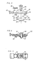
- the hinge arm 1 consists of a stamped sheet metal part, the side legs 2 of which are angled in a U-shape from the central web part 3.
- the hinge arm 1 is at its front end with s Provide holes 4 which serve to receive hinge pins of any joints, for example the handlebars of four-joint hinges.
- the legs 2 of the hinge arm 1 are provided with non-visible elongated holes which run freely towards the rear and into which the peg-like projections 6 (see FIG. 6) of the intermediate plate 7 engage.
- the intermediate plate 7 is also made from a stamped sheet metal part, the sides 8 of which are angled in a U-shaped manner from the central web part 9.
- the pin-like projections 6 are formed in these angled legs 8.
- the legs 8 are provided with obliquely extending elongated holes 10, which are penetrated by pins 11, the ends of which are riveted into holes in the legs 2 of the hinge arm 1.
- a set screw 14 is screwed into a threaded bore of the web part 3 of the hinge arm 1 and has a lower, tapered shaft part with a screwed-in annular groove.
- This annular groove is held in an elongated hole 16, which is arranged so that it runs freely on the front edge of the web part 9 of the intermediate plate 7.
- the legs 8 of the intermediate plate 7 are provided in their end regions with teeth 17, 18 pointing downwards. Those teeth the NEN the claws on areas of the base plate 20, preferably provided with grooves, when the hinge arm 1 is clamped to the base plate 20 via the intermediate plate 7 by the fastening screw 21 without the hook plate 25 being interposed. This type of attachment is shown in Fig. 6.
- the intermediate plate 7 is provided in its web part 9 with a keyhole-shaped elongated hole 22, wherein the circularly enlarged hole part is larger in diameter than the head of the fastening screw 21, so that the intermediate plate with its widened region of the Elongated hole 22 is attached to the fastening screw 21 and the area of the elongated hole 22 with the smaller diameter can be pushed under the head of the fastening screw 21 with a short displacement path, which is then tightened to fix the intermediate plate 7 and thus also the hinge arm 1 on the base plate 20 .
- the hinge arm 1 is provided in its web part 3 with an approximately rectangular window-like cutout 27.
- the keyhole-like elongated hole 22 is provided in the web part 3 of the hinge arm 1 instead of the window 27.
- the intermediate plate 7 can be screwed to the hook plate 25 by a fastening screw 26.
- the hook plate 25 consists of a central holding part 30, which is formed from a transverse yoke 31, the leg-shaped lateral bar at right angles to this carries 32.
- the transverse yoke 31 is provided in its central region with an annular base 33 through which the threaded hole for the fastening screw 26 is passed.
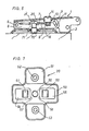
- this has a central groove-like guide for the slide 34.
- This slide 34 consists of an elongated central part 35, which has a rectangular cross section, which corresponds to the cross section of the guide groove between the strips 32 in the holding part 30.
- the slider 34 is inserted into the guide groove of the holding part 30 in the manner shown in FIG. 4, with lateral projections 36 forming stops for the right end edges of the strips 32.
- the middle part 35 of the slide 34 is provided on its upper side with a flat recess 37 into which a U-shaped compression spring 38 with crossing legs is inserted in the manner shown in FIGS. 4 and 5.
- the web portion of the compression spring 38 connecting the legs is held in an outwardly facing retaining groove 39 of the recess 37.
- the ends of the legs of the compression spring 38 are supported on the inner surfaces of the strips 32 of the holding part 30.
- the slider 34 is provided with an outward opening button 40.
- the middle part 35 of the slide 34 is provided with an elongated hole 41 which passes through the fastening screw 26 screwed into the middle threaded bore of the holding part 30.
- the slide 34 is provided on both sides of the transverse yoke 31 of the holding part 30 with hook-shaped projections 43 and 44, the hook parts of which are aligned.
- the hook-like projections 43, 44 have rounded heads 45 to form ramp-like sliding edges.
- the hook-like holding flanks 46 can be slightly beveled for clamping bracing.
- the holding part 30 is a m die-cast part, preferably made of a suitable zinc alloy.
- the base plate 20 consists of a stamped sheet metal part and is symmetrical about both its longitudinal and transverse center lines, so that left and right-hand assemblies are possible.
- the base plate 20 consists of a rectangular middle part 50, which serves to fasten the hinge arm 1.
- Flange-like extensions 51 are formed in the center on both sides and have fastening bores 52 for fastening to a supporting wall or the like.
- the middle part is provided between two base-like elevations 54, 55 with a threaded bore 56 for screwing in the fastening screw 21.
- the distance between the inner edges 57, 58 of the base-like elevations 54, 55 corresponds to the width of the yoke part 31, so that it can reach centering between the base-like elevations 54, 55.
- the base-like elevations 54, 55 are provided symmetrically with respect to the transverse center line with latching openings 60, 61. These have slightly beveled edges.
- the distance between the latching openings 60, 61 corresponds to the distance between the hook-like projections 44, 45 on the slide 34 from one another.
- the end regions of the leg-like webs 32 of the holding part 30 are provided with elevations 65 so that the holding part 30 can be tensioned by the fastening screw 26 against the web part 9 of the intermediate plate 7 in the manner shown in FIG. 1, so that the slide 34 is freely displaceable longitudinally between the groove formed in the holding part 30 on the one hand and the web part 9 of the intermediate plate 7 on the other hand.
- the fastening screw 21, which is used for the direct fastening of the hinge arm 1 on the base plate 20 without an intermediate hook plate 25, has in its lower region a threaded section 70 with a larger diameter.
- the threaded bore 56 of the base plate 20 carries the internal thread corresponding to the threaded section 70.
- the fastening screw 21 is provided with a tapered threadless shaft part 71, the diameter of which corresponds to the outside diameter of the thread of the fastening screw 26.
- the underside of the hook plate 25 is pressed onto the base plate 20 after the heads 45 of the hook-like projections 43 and 44 have been inserted into the latching openings 60 and 61 by pressure exerted on the hinge arm 1.
Landscapes
- Engineering & Computer Science (AREA)
- Mechanical Engineering (AREA)
- Hinges (AREA)
Priority Applications (1)
| Application Number | Priority Date | Filing Date | Title |
|---|---|---|---|
| AT87110986T ATE62053T1 (de) | 1986-08-11 | 1987-07-29 | Scharnierarm fuer ein moebelscharnier o.dgl. |
Applications Claiming Priority (2)
| Application Number | Priority Date | Filing Date | Title |
|---|---|---|---|
| DE3627170A DE3627170C1 (de) | 1986-08-11 | 1986-08-11 | Scharnierarm fuer ein Moebelscharnier o.dgl.,mit Grundplatte direkt oder indirekt verbindbar |
| DE3627170 | 1986-08-11 |
Publications (3)
| Publication Number | Publication Date |
|---|---|
| EP0256376A2 true EP0256376A2 (fr) | 1988-02-24 |
| EP0256376A3 EP0256376A3 (en) | 1988-07-06 |
| EP0256376B1 EP0256376B1 (fr) | 1991-03-27 |
Family
ID=6307146
Family Applications (1)
| Application Number | Title | Priority Date | Filing Date |
|---|---|---|---|
| EP87110986A Expired - Lifetime EP0256376B1 (fr) | 1986-08-11 | 1987-07-29 | Bras de charnière pour une charnière de meuble |
Country Status (4)
| Country | Link |
|---|---|
| EP (1) | EP0256376B1 (fr) |
| AT (1) | ATE62053T1 (fr) |
| DE (1) | DE3627170C1 (fr) |
| ES (1) | ES2021647B3 (fr) |
Cited By (2)
| Publication number | Priority date | Publication date | Assignee | Title |
|---|---|---|---|---|
| EP0791714A1 (fr) * | 1996-02-14 | 1997-08-27 | Julius Blum Gesellschaft m.b.H. | Charnière |
| EP0821125A1 (fr) * | 1996-07-22 | 1998-01-28 | Arturo Salice S.p.A. | Bras de charnière réglable |
Families Citing this family (8)
| Publication number | Priority date | Publication date | Assignee | Title |
|---|---|---|---|---|
| JPH063088B2 (ja) * | 1988-05-16 | 1994-01-12 | スガツネ工業株式会社 | ヒンジ |
| DE3841405A1 (de) * | 1988-06-29 | 1990-01-04 | Salice Arturo Spa | Scharnierarm mit einer befestigungsplatte zu dessen befestigung an einem moebelteil o. dgl. |
| EP0369532B1 (fr) * | 1988-11-16 | 1994-04-13 | Franco Ferrari | Charnière de porte à accouplement rapide |
| ES1009089Y (es) * | 1989-02-17 | 1989-12-16 | Blanco Eguiluz M. Begona | Dispositivo de enganche rapido para bisagras de muebles. |
| ATE112358T1 (de) * | 1989-12-25 | 1994-10-15 | Murakoshi Seiko Kk | Scharnier. |
| AT398801B (de) * | 1990-05-16 | 1995-02-27 | Blum Gmbh Julius | Scharnier |
| ATE135079T1 (de) * | 1990-12-27 | 1996-03-15 | Lama | Schnellverbindungsmöbelscharnier |
| US5224242A (en) * | 1991-07-16 | 1993-07-06 | Mednarodno Podjetje Lama, D.D. | Quick-assembling furniture hinge |
Family Cites Families (11)
| Publication number | Priority date | Publication date | Assignee | Title |
|---|---|---|---|---|
| DE2044096A1 (de) * | 1970-09-05 | 1972-03-16 | Kunststoff Gmbh, 4900 Herford | Möbel mit mindestens einer Anschlagtür |
| AT340270B (de) * | 1973-12-24 | 1977-12-12 | Blum Gmbh | Einstellbares scharnier |
| AT337566B (de) * | 1973-12-31 | 1977-07-11 | Blum Gmbh | Langen- und hoheneinstellbares scharnier |
| AT340803B (de) * | 1974-02-06 | 1978-01-10 | Blum Gmbh | Hohen- und tiefeneinstellbares scharnier mit einer auf einem mobelteil od.dgl. anschlagbaren grundplatte und einem zwischenstuck |
| DE2719890C2 (de) * | 1976-05-06 | 1986-03-20 | Paul Hettich & Co, 4983 Kirchlengern | Scharnier |
| DE2735825A1 (de) * | 1977-08-09 | 1979-02-22 | Heinze Fa R | Moebelscharnier |
| DE2736333A1 (de) * | 1977-08-12 | 1979-02-22 | Heinze Fa R | Moebelscharnier |
| DE3119571A1 (de) * | 1981-05-16 | 1982-12-16 | Karl Lautenschläger KG, Möbelbeschlagfabrik, 6107 Reinheim | "moebelscharnier" |
| DE3448346C2 (fr) * | 1983-12-30 | 1990-12-13 | Julius Blum Ges.M.B.H., Hoechst, At | |
| DE3426672A1 (de) * | 1984-07-19 | 1986-01-30 | Arturo Salice S.P.A., Novedrate, Como | Scharnierarm fuer ein moebelscharnier o. dgl. |
| AT383643B (de) * | 1984-10-19 | 1987-07-27 | Blum Gmbh Julius | Scharnier |
-
1986
- 1986-08-11 DE DE3627170A patent/DE3627170C1/de not_active Expired
-
1987
- 1987-07-29 EP EP87110986A patent/EP0256376B1/fr not_active Expired - Lifetime
- 1987-07-29 AT AT87110986T patent/ATE62053T1/de not_active IP Right Cessation
- 1987-07-29 ES ES87110986T patent/ES2021647B3/es not_active Expired - Lifetime
Cited By (2)
| Publication number | Priority date | Publication date | Assignee | Title |
|---|---|---|---|---|
| EP0791714A1 (fr) * | 1996-02-14 | 1997-08-27 | Julius Blum Gesellschaft m.b.H. | Charnière |
| EP0821125A1 (fr) * | 1996-07-22 | 1998-01-28 | Arturo Salice S.p.A. | Bras de charnière réglable |
Also Published As
| Publication number | Publication date |
|---|---|
| ATE62053T1 (de) | 1991-04-15 |
| DE3627170C1 (de) | 1988-03-24 |
| EP0256376B1 (fr) | 1991-03-27 |
| EP0256376A3 (en) | 1988-07-06 |
| ES2021647B3 (es) | 1991-11-16 |
Similar Documents
| Publication | Publication Date | Title |
|---|---|---|
| EP0168731B1 (fr) | Charnière pour meuble | |
| EP0761130B1 (fr) | Ferrure de fixation pour panneaux frontaux de tiroir | |
| DE2723850C2 (de) | Möbelscharnier | |
| EP0528213B1 (fr) | Elément de ferrure fixé par serrage dans une gorge profilée ayant au moins une contre-dépouille | |
| DE4219681C2 (de) | Einstellbares Abhebescharnier | |
| EP0080556A1 (fr) | Serrure enfichable à serrage pour l'assemblage amovible de deux éléments de construction | |
| DD292294A5 (de) | Fuehrungsanordnung | |
| EP0256376B1 (fr) | Bras de charnière pour une charnière de meuble | |
| EP0234544B1 (fr) | Plaque de base pour la fixation d'un bras de charnière d'une charnière pour meubles ou similaires | |
| DE2721625C2 (fr) | ||
| EP0241660B1 (fr) | Plaque de base pour la fixation d'un bras de charnière d'une charnière pour meubles ou similaires | |
| EP0168595B1 (fr) | Bras de charnière pour charnière de meuble | |
| DE2722758A1 (de) | Scharnier, insbesondere moebelscharnier | |
| DE2735825C2 (fr) | ||
| EP0255692B1 (fr) | Bras de charnière pour charnière de meuble ou similaire | |
| DE2356000A1 (de) | Moebelscharnier | |
| DE4341422C2 (de) | Topfscharnier | |
| AT1063U1 (de) | Duschtrennwand | |
| DE4216612A1 (de) | Einachsscharnier | |
| DE3500423A1 (de) | Scharnier, insbesondere fuer moebel | |
| DE3521051C2 (fr) | ||
| EP0843061B1 (fr) | Ferrure pour fenêtre | |
| DE2720096A1 (de) | Moebelscharnier | |
| DE4420037A1 (de) | Vorrichtung zur Befestigung eines Verbindungselements in einer Aufnahmeöffnung eines Bauteils und dafür geeigneter Vierkantstift | |
| DE3301509C2 (de) | Ecklager für Drehkippflügel von Fenstern, Türen od.dgl. |
Legal Events
| Date | Code | Title | Description |
|---|---|---|---|
| PUAI | Public reference made under article 153(3) epc to a published international application that has entered the european phase |
Free format text: ORIGINAL CODE: 0009012 |
|
| AK | Designated contracting states |
Kind code of ref document: A2 Designated state(s): AT ES GB IT |
|
| PUAL | Search report despatched |
Free format text: ORIGINAL CODE: 0009013 |
|
| AK | Designated contracting states |
Kind code of ref document: A3 Designated state(s): AT ES GB IT |
|
| 17P | Request for examination filed |
Effective date: 19881215 |
|
| 17Q | First examination report despatched |
Effective date: 19900522 |
|
| GRAA | (expected) grant |
Free format text: ORIGINAL CODE: 0009210 |
|
| AK | Designated contracting states |
Kind code of ref document: B1 Designated state(s): AT ES GB IT |
|
| REF | Corresponds to: |
Ref document number: 62053 Country of ref document: AT Date of ref document: 19910415 Kind code of ref document: T |
|
| ITF | It: translation for a ep patent filed | ||
| GBT | Gb: translation of ep patent filed (gb section 77(6)(a)/1977) | ||
| PGFP | Annual fee paid to national office [announced via postgrant information from national office to epo] |
Ref country code: GB Payment date: 19910624 Year of fee payment: 5 |
|
| PLBE | No opposition filed within time limit |
Free format text: ORIGINAL CODE: 0009261 |
|
| STAA | Information on the status of an ep patent application or granted ep patent |
Free format text: STATUS: NO OPPOSITION FILED WITHIN TIME LIMIT |
|
| 26N | No opposition filed | ||
| PG25 | Lapsed in a contracting state [announced via postgrant information from national office to epo] |
Ref country code: GB Effective date: 19920729 |
|
| GBPC | Gb: european patent ceased through non-payment of renewal fee |
Effective date: 19920729 |
|
| PGFP | Annual fee paid to national office [announced via postgrant information from national office to epo] |
Ref country code: ES Payment date: 20040707 Year of fee payment: 18 |
|
| PGFP | Annual fee paid to national office [announced via postgrant information from national office to epo] |
Ref country code: AT Payment date: 20040721 Year of fee payment: 18 |
|
| PG25 | Lapsed in a contracting state [announced via postgrant information from national office to epo] |
Ref country code: IT Free format text: LAPSE BECAUSE OF NON-PAYMENT OF DUE FEES;WARNING: LAPSES OF ITALIAN PATENTS WITH EFFECTIVE DATE BEFORE 2007 MAY HAVE OCCURRED AT ANY TIME BEFORE 2007. THE CORRECT EFFECTIVE DATE MAY BE DIFFERENT FROM THE ONE RECORDED. Effective date: 20050729 Ref country code: AT Free format text: LAPSE BECAUSE OF NON-PAYMENT OF DUE FEES Effective date: 20050729 |
|
| PG25 | Lapsed in a contracting state [announced via postgrant information from national office to epo] |
Ref country code: ES Free format text: LAPSE BECAUSE OF NON-PAYMENT OF DUE FEES Effective date: 20050730 |
|
| REG | Reference to a national code |
Ref country code: ES Ref legal event code: FD2A Effective date: 20050730 |