EP0256445B1 - Elektrisch betätigtes Durchflussventil - Google Patents
Elektrisch betätigtes Durchflussventil Download PDFInfo
- Publication number
- EP0256445B1 EP0256445B1 EP19870111452 EP87111452A EP0256445B1 EP 0256445 B1 EP0256445 B1 EP 0256445B1 EP 19870111452 EP19870111452 EP 19870111452 EP 87111452 A EP87111452 A EP 87111452A EP 0256445 B1 EP0256445 B1 EP 0256445B1
- Authority
- EP
- European Patent Office
- Prior art keywords
- solenoid
- port
- magnetic
- housing
- armature
- Prior art date
- Legal status (The legal status is an assumption and is not a legal conclusion. Google has not performed a legal analysis and makes no representation as to the accuracy of the status listed.)
- Expired
Links
- 239000012530 fluid Substances 0.000 title claims description 29
- 238000007493 shaping process Methods 0.000 claims description 4
- 230000015572 biosynthetic process Effects 0.000 claims description 2
- 238000005755 formation reaction Methods 0.000 claims 1
- 238000000926 separation method Methods 0.000 claims 1
- 230000006835 compression Effects 0.000 description 4
- 238000007906 compression Methods 0.000 description 4
- 238000004519 manufacturing process Methods 0.000 description 2
- 229920003023 plastic Polymers 0.000 description 2
- 239000004033 plastic Substances 0.000 description 2
- 238000010926 purge Methods 0.000 description 2
- 230000000694 effects Effects 0.000 description 1
- 230000001788 irregular Effects 0.000 description 1
- 230000001105 regulatory effect Effects 0.000 description 1
- 230000035945 sensitivity Effects 0.000 description 1
Images
Classifications
-
- F—MECHANICAL ENGINEERING; LIGHTING; HEATING; WEAPONS; BLASTING
- F16—ENGINEERING ELEMENTS AND UNITS; GENERAL MEASURES FOR PRODUCING AND MAINTAINING EFFECTIVE FUNCTIONING OF MACHINES OR INSTALLATIONS; THERMAL INSULATION IN GENERAL
- F16K—VALVES; TAPS; COCKS; ACTUATING-FLOATS; DEVICES FOR VENTING OR AERATING
- F16K31/00—Actuating devices; Operating means; Releasing devices
- F16K31/02—Actuating devices; Operating means; Releasing devices electric; magnetic
- F16K31/06—Actuating devices; Operating means; Releasing devices electric; magnetic using a magnet, e.g. diaphragm valves, cutting off by means of a liquid
- F16K31/0675—Electromagnet aspects, e.g. electric supply therefor
-
- H—ELECTRICITY
- H01—ELECTRIC ELEMENTS
- H01F—MAGNETS; INDUCTANCES; TRANSFORMERS; SELECTION OF MATERIALS FOR THEIR MAGNETIC PROPERTIES
- H01F7/00—Magnets
- H01F7/06—Electromagnets; Actuators including electromagnets
- H01F7/08—Electromagnets; Actuators including electromagnets with armatures
- H01F7/16—Rectilinearly-movable armatures
- H01F7/1607—Armatures entering the winding
Definitions
- the present invention relates to a solenoid fluid valve having a moving magnetic part arranged to open and close a valve seat influenced by a return spring and aims to effect economies in a three-port fluid valve desired to deliver a high pressure output, or a low pressure output (purge or exhaust) according to electric inputs selected.
- the valve may in turn control the position of a slide valve in a hydraulic circuit, eg for shifting the different gears in a vehicle or machine gear box where the actual ratio shifting is performed by fluid power.
- Some such gear boxes will have automatic ratio selection too, ie be fully automatic.
- the present invention provides that a two part armature moved by a solenoid coil be used, with the starting, unenergized relative positions of the two having a finite but small spacing, which can be regulated, eg by hand.
- the invention is not concerned with the secondary, slide valve details, but with the solenoid valve.
- a two part armature is disclosed in WO-A-87/00963 unpublished at the claimed priority date of the present application, and referring to DE-U-8 029 580.
- GB-A-2 069 104 discloses a solenoid valve according to the pre-characterizing portion of Claim 1 and represents the state of the art. Admittedly it is possible to set not only the magnetic characteristics, but also the amplitude of the stroke of the closure actuators, between two states of the valve. There are however many component parts and it is quite complicated to assemble the valve and to store the many components. The invention aims to simplify these, while maintaining adjustability of magnetic sensitivity, in the case either of either a normally closed or a normally open passageway between two adjacent ports; such passageway being fluidly connected towards the third port past a moving part of the armature, as in the state of the art.
- DE-A1-3 134 613 shows a single end body having conduits and a valve seat formed in it, but the valve is not adjustable, has no plug-in facility for the end body, and the securing of the top and bottom end bodies are not clearly shown - certainly appearing more cumbesome eg. in Fig.2 of this publication.
- the invention is characterized by claim 1, and subclaims define normally open and normally closed options, also a refinement where an outer jacket for the solenoid and forming part of the housing, is attached to the lower end member containing the first two ports and an upper end member accommodating the third port.
- Claim 2 and 3 provide advantageous and economical manufacturing methods, giving a robust and practical plug-in facility; securely retaining magnetic parts and the common housing end member.
- Such a valve when unenergized can be of the type having an output port connected either to the higher pressure of two input ports, or to the lower pressure of two inputs. When energized it will have the output port connected to the other of the two input ports, in each case.
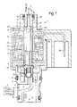
- the solenoid valve 1 shown has a higher pressure input port 2 marked “supply” for connecting to a pressure source 3 through a filter 4, a lower pressure input port 5 marked “exhaust” eg for purging to a reservoir perhaps at atmospheric pressure, and an output port 6 for "control” purposes, eg to control a slide valve.
- the output port 6 can be connected by the solenoid either to the "supply” port 2 or to the "exhaust” port 5 through an interior space 7 within the housing 8 of the valve which is always in communication with output port 6.
- the interior space 7 communicates with a further space 9 near an exhaust port valve seating 10 by virtue of clearances between, a fixed armature part 11 and a movable armature part 12 of hexagonal cross-section forming a two-part armature, and a cylindrical guide wall 13 for the movable armature, which wall is formed by a casing or former for the solenoid coil 14.
- the coil and its former are held in axial position by a transverse wall 15 through which the fixed armature 11 passes and is secured eg at a reduced diameter lower end portion 16.
- Transverse wall 15 has a number of holes 17 machined in it towards where the fixed armature passes through, to complete the fluid communication path between spaces 7 and 9.
- a supply valve seating 18 in the fluid path between ports 2 and 6 is normally not obturated by a ball 19 held against a captive coil spring 20 as shown in the drawing, and the exhaust valve seating 10 in the fluid path between ports 6 and 5 is normally obturated by a formed end 21 of the movable armature 12.
- Ball 19 is normally held off its seating 18 by a compression spring 22 acting against a shoulder formed on the outside of a holder 24 for the ball.
- the ball holder has an axial extension acting as a push rod 25 which abuts movable armature 12. Therefore the same means, ie compression spring 22, normally holds supply seating 18 unblocked, and exhaust seating 10 blocked.
- the magnetic circuit comprises the armatures, transverse plate 15, the part 26 of housing 8 partly surrounding the coil and a top transverse piece 27 of the housing which is partly disc-shaped.
- the magnetic circuit may not completely surround the coil and armature, eg where the terminals 28 exit the toroidal coil former 29 or where holes 17 are required for fluid communication.
- Movable armature 12 requires an irregular exterior, eg hexagonal both to bear against the sides and to allow fluid passage.
- Fluid tightness may be assisted by O-rings 30, 31, and 32.
- the normal or starting gap 33 between the armatures is critical, magnetically so as not to require initially an excess of electrical power, and mechanically to provide during energization just sufficient compression of spring 20 for satisfactory seating of ball 19.
- the return spring 22 needs to be strong enough to return the movable armature quickly on de-energization and to reseat it properly on exhaust seating 10, but spring 22 should not require excess electric magnetic power to compress it or to prevent good seating of ball 19. So the choice of armature gap 33 and the spring rates is a compromise.
- magnetic gap 33 is externally adjustable, in that a cylindrical non-magnetic eg plastics part 34 axially bored at 35 for the second output, ie the exhaust fluid passage, has a screw-driver slot 36 and an external threading 37.
- This seat 10 is adjusted in position, and hence the normal air gap can be zeroed by screwing in, and set accurately by unscrewing a known number of turns or part-turns.
- the top of housing 8 can be a separate magnetic piece 38 having internal threading to cooperate with threading 37 and a flange to provide transverse magnetic circuit member 27.
- Piece 38 may be held by a turned over lip 39 from the vertical side 26 of the housing portion surrounding the coil.
- O-ring 30 in a groove eg between ridges on plastics part 34 will enable the screwing without losing fluid and pressure.
- the valve can be energized with minimum power, but the hydraulic fluid output pressure at "control" port 6 can conveniently operate a slide valve between two positions which latter can handle much higher pressures, and so acts as a relay.
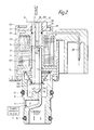
- FIG. 2 differences from Figure 1 are that the supply or high pressure seat 18 is normally closed and the exhaust seat 10 is normally open, when coil 14 is unenergized; also that the fixed armature 11 and adjustable non-magnetic adjustable piece 34 of Figure 1 are replaced by one fixed armature 101 which itself is adjustable or pre-selectable as regards axial position by screw-driver slot 36 and threading 37. Also movable armature 102 now differs in having a "supply" pressure closure formation 103 at its normally obturating lower end as well as the exhaust seat closure spherical shaping 104 at its normally unblocking upper end.
- the moving armature has also a ridge 105, eg a circular clip in a throat or groove therein, against which a compression spring 106 having its other end braced against the transverse wall 15, normally abuts seat 18.
- the spring 106 must be strong enough to overcome the supply pressure at this seat, but not strong enough to prevent opening by the energized coil, for a suitable adjustment of gap 33.
- two of the Figure 2 valves may relay control to respective slide valves in a hydraulically driven gear ratio shifter.
- the coil 14 When the coil 14 is unenergized, the sprung mobile armature abuts the supply seat but its hexagonal sides allow control port 6 to communicate with the open exhaust seat 10 and exhaust conduit 35.
- mobile armature 102 On energization, mobile armature 102 is drawn upwards to abut the fixed armature, to close off the exhaust, and to open seat 18 and the control port 6 to the "supply" pressure.
- a powered gear-shifting system may use two of the Figure 1 valves (supply normally "on”) and one of the valves illustrated in Figure 2 (supply 3 normally disconnected from the valve interior and hence from the controlled output port 6).
Landscapes
- Physics & Mathematics (AREA)
- Electromagnetism (AREA)
- Engineering & Computer Science (AREA)
- General Engineering & Computer Science (AREA)
- Mechanical Engineering (AREA)
- Power Engineering (AREA)
- Magnetically Actuated Valves (AREA)
Claims (9)
- Magnetventil für Fluide mit einem Eingangs- und einem Ausgangsanschluß (2,6), die voneinander mittels eines in einem Ventilgehäuse (8) befindlichen Fluidkanals (7) getrennt sind; mit einem Magnetkreis, der zum verschließen einer Öffnung (18) des Kanals ein unter dem Einfluß einer vorspannung (22,106) stehendes bewegliches magnetisches Element (12,102) enthält; sowie mit einem zweiten magnetischen Element (11,101), das während der Betätigung der Magnetspule festliegt und von dem beweglichen Element durch einen Luftspalt (33) beabstandet ist, wobei der Spalt die Charakteristik der magnetischen Betätigung beeinflußt und im Betrieb jeweils bei der Beaufschlagung der Magnetspule mit Strom reversibel verkleinert wird und das die festen sowie das bewegliche magnetische Element somit einen zweiteiligen Anker bilden; und mit einstellbaren, von außerhalb des Ventilgehäuses (8) zugänglichen Mitteln (36) zum Wählen der Ruheabmessungen (bei stromloser Magnetspule) des Spaltes (33); wobei die Gestalten der beiden in der sie umgebenden Führung (13) befindlichen magnetischen Elemente des Ankers derart sind, daß sie in wenigstens einem Betätigungszustand der Magnetspule einen Fluidstrom von dem Kanal (7) entlang der Anordnung und durch den Spalt (33) gestatten; wodurch der somit mögliche Strom einen dritten Anschluß (5) nutzt, so daß zwei Strömungszustände vorgesehen sind; dadurch gekennzeichnet, daß
der Eingangsanschluß (2), der Ausgangsanschluß (6), die zu betätigende Öffnung (18) und der Fluidkanal einstückig in einem gemeinsamen Endabschnitt des Gehäuses (8) ausgebildet sind;
daß der gemeinsame Endabschnitt des Gehäuses (8) einen wesentlich kleineren Querschnitt aufweist, als ein Abschnitt (26) des die Magnetspule umgebenden Gehäuses, so daß eine Einsteckmöglichkeit bis zu einer bestimmten, durch Anstoßen an den die Magnetspule umgebenden Gehäuseabschnitt (26) festgelegten Tiefe ermöglicht wird;
und daß ein separates magnetisches Element (38) einen Teil des Magnetkreises bildet, ein den dritten Anschluß (5) an einem Ende gegenüber des gemeinsamen Gehäuseendstücks bildendes Element (34,101) umfaßt und an dem gegenüberliegenden Ende von einer umgebördelten Lippenanordnung (39) des die Magnetspule umgebenden Gehäuseabschnitts (26) gehalten wird, wobei der Gehäuseabschnitt auch einen quer sich erstreckenden Abschnitt (27) des magnetischen Elements (38) umgibt. - Magnetventil für Fluide nach Anspruch 1, bei dem der den Magneten umgebende Abschnitt ebenfalls die Form einer umgebördelten Lippenanordnung aufweist und wobei die Anordnung sowohl einen radial nach außen gerichteten Flansch des gemeinsamen Endabschnitts des Gehäuses als auch ein quer sich erstreckendes Stirnwandglied des Magnetkreises hält; und daß das Stirnwandglied (15) eine Gruppe von Löchern aufweist, um einen Teil des Ankers sowie Fluide entlang seiner Außenwand passieren zu lassen.
- Magnetventil für Fluide nach Anspruch 1 oder 2, dadurch gekennzeichnet, daß das zweite magnetische Element (11) eine innere Führungsfläche für eine zentral gleitende Schubstange (25) aufweist, deren eines Ende sich zu dem ersten Element (12) an diesem anliegend erstreckt, wobei die Schubstange (25) mit einem den Ventilsitz verschließenden Element (19) verbunden ist, und die Vorspannung (22) die Schubstange (25) in Richtung auf die Anlage drückt, und daß das erste magnetische Element (12) bei einer Versorgung der Magnetspule mit Strom bewegt wird und die Schubstange (25) entgegen der Vorspannung (22) antreibt und dadurch das verschließende Element gegen seinen Ventilsitz (18) treibt, wodurch der zweite Anschluß (6) ausgehend von seinem im Ruhezustand normalerweise offenen oder durchlässigen Zustand verschlossen wird.
- Magnetventil für Fluide nach Anspruch 3, dadurch gekennzeichnet, daß das erste magnetische Element (12) während seiner Bewegung auch einen zweiten Ventilsitz (10) öffnet, der dem dritten Anschluß (5) benachbart angeordnet ist, so daß der dritte Anschluß (5) dadurch mit der entsprechend den Betriebszuständen möglichen Strömung entlang den Ankeiteilen beaufschlagt wird.
- Magnetventil für Fluide nach Anspruch 4, dadurch gekennzeichnet, daß der sich zweite Ventilsitz (10) an dem inneren Ende einer Bohrung (35) durch ein nichtmagnetisches Element (34) befindet, das in das Gehäuse eingeschraubt ist (37) und sowohl den dritten Anschluß (5) als auch die zugänglichen einstellbaren Mittel (36) darstellt.
- Magnetventil für Fluide nach Anspruch 3, dadurch gekennzeichnet, daß das (erste) den Ventilsitz verschließende Element (19) unter einer Vorspannung (20) in Richtung des Verschließens und von der Schubstange (25) weg gerichtet steht, und daß der (Anfangs- oder Ruhe-) Spalt (33) in unbetätigtem Zustand auf einen Wert eingestellt werden kann, so daß wegen der magnetischen Wirkung anfangs keine übermäßige elektrische Leistung für die Magnetspule notwendig ist, während gleichzeitig mechanisch ein ausreichender Weg zur Verfügung steht, damit die Vorspannung (20) für das verschließende Element ein ausreichendes Verschließen erlaubt; wobei die erstgenannte Vorspannung (22) kräftig genug ist, um die Schubstange (25) und den beweglichen Ankerteil (12) der Anordnung bei einem Abschalten schnell genug zurückzuziehen, ohne andererseits andauernde übermäßige elektrische Leistung an dem Magneten zu erfordern und ohne eine ausreichende Abdichtung zu beeinträchtigen.
- Magnetventil für Fluide nach Anspruch 1, dadurch gekennzeichnet, daß
das zweite Element (101) in das Gehäuse (8) eingeschraubt (37) ist, eine in Längsrichtung verlaufende Bohrung (35) enthält, die zugänglichen einstellbaren Mittel (36) an seinem aus dem Gehäuse herausragenden Ende trägt, das außerdem den dritten Anschluß (5) bildet, sowie einen Ventilsitz (10) an seinem inneren Ende aufweist, der im Ruhezustand (bei stromloser Magnetspule) nicht von einem an einem Ende des ersten beweglichen magnetischen Ankerteils (102) befindlichen Verschlußglied (104) verschlossen wird, wobei der Abstand zwischen diesen Enden dieser Teile (102,101) den Spalt bildet, dessen Ruhewert mittels der Einstellmittel (36) einstellbar ist; und wobei
das andere Ende (103) des beweglichen Ankerteils (102) ebenfalls ein Verschlußglied bildet, das im Ruhezustand an einem Ventilsitz (18) anliegt, so daß bei Beaufschlagung mit Strom der bewegliche Teil (102) entgegen der Vorspannung (106) bewegt wird, um den im Ruhezustand geschlossenen Sitz (18) zu öffnen und den im Ruhezustand geöffneten Sitz (10) zu verschließen; wobei ein Fluidstrom zwischen der Außenseite des Gliedes und seiner Führung (13) wegen ihrer nicht übereinstimmenden, einander gegenüberliegenden Oberflächen möglich ist. - Magnetventil für Fluide nach einem der Ansprüche 1-7, dadurch gekennzeichnet, daß ein internes Volumen (7) vorhanden ist, das mit dem zweiten Anschluß (6) ständig und im Ruhezustand nur mit entweder dem ersten (2) oder dem dritten (5) Anschluß strömungsmäßig in Verbindung steht und das bei mit Strom beaufschlagter Magnetspule nur mit dem jeweils anderen Anschluß, entweder dem ersten (2) oder dem dritten (5) Anschluß strömungsmäßig in Verbindung steht, und daß die strömungsmäßige Verbindung des internen Volumens (7) mit dem dritten Anschluß (5) immer entlang der beiden Elemente des Ankers erfolgt.
- Magnetventil für Fluide nach Anspruch 8, dadurch gekennzeichnet, daß der erste Anschluß (2) mit einer Druckversorgungsquelle (3) verbunden ist, daß der dritte Anschluß (5) mit einem Auslaßmittel verbunden ist, und daß der zweite Anschluß (6) eine Steuerfunktion mit zwei Zuständen je nach der Beaufschlagung oder Nichtbeaufschlagung der Magnetspule mit Strom ausübt.
Applications Claiming Priority (2)
| Application Number | Priority Date | Filing Date | Title |
|---|---|---|---|
| GB8619868 | 1986-08-15 | ||
| GB868619868A GB8619868D0 (en) | 1986-08-15 | 1986-08-15 | Fluid valve |
Publications (3)
| Publication Number | Publication Date |
|---|---|
| EP0256445A2 EP0256445A2 (de) | 1988-02-24 |
| EP0256445A3 EP0256445A3 (en) | 1989-02-22 |
| EP0256445B1 true EP0256445B1 (de) | 1992-05-13 |
Family
ID=10602742
Family Applications (1)
| Application Number | Title | Priority Date | Filing Date |
|---|---|---|---|
| EP19870111452 Expired EP0256445B1 (de) | 1986-08-15 | 1987-08-07 | Elektrisch betätigtes Durchflussventil |
Country Status (3)
| Country | Link |
|---|---|
| EP (1) | EP0256445B1 (de) |
| DE (1) | DE3779006D1 (de) |
| GB (1) | GB8619868D0 (de) |
Cited By (1)
| Publication number | Priority date | Publication date | Assignee | Title |
|---|---|---|---|---|
| CN107735608A (zh) * | 2015-04-10 | 2018-02-23 | 艾酷阀门公司 | 电磁式流体控制阀组件 |
Families Citing this family (14)
| Publication number | Priority date | Publication date | Assignee | Title |
|---|---|---|---|---|
| US4829275A (en) * | 1988-06-27 | 1989-05-09 | Croy Dennis P | Method and means for providing consistent operation of a solenoid actuator |
| EP0660016B1 (de) * | 1993-12-17 | 2000-06-07 | Eaton S.A.M. | Einstellbares Magnetventil |
| DE102012106683A1 (de) * | 2012-07-24 | 2014-01-30 | Dorma Gmbh & Co. Kg | Magnetventil |
| US12031755B2 (en) | 2021-05-19 | 2024-07-09 | Copeland Lp | Refrigeration system having high-efficiency loop |
| CN113175555B (zh) * | 2021-05-21 | 2025-01-17 | 嘉兴市大宇机电有限公司 | 一种脉冲阀用电磁控制执行器 |
| US11655813B2 (en) | 2021-07-29 | 2023-05-23 | Emerson Climate Technologies, Inc. | Compressor modulation system with multi-way valve |
| US20230296097A1 (en) * | 2022-03-16 | 2023-09-21 | Emerson Climate Technologies, Inc. | Modulated Compressor And Valve Assembly |
| US12259163B2 (en) | 2022-06-01 | 2025-03-25 | Copeland Lp | Climate-control system with thermal storage |
| US11846287B1 (en) | 2022-08-11 | 2023-12-19 | Copeland Lp | Scroll compressor with center hub |
| US11965507B1 (en) | 2022-12-15 | 2024-04-23 | Copeland Lp | Compressor and valve assembly |
| US12416308B2 (en) | 2022-12-28 | 2025-09-16 | Copeland Lp | Compressor with shutdown assembly |
| US12669126B2 (en) | 2023-08-08 | 2026-06-30 | Copeland Lp | Compressor having shutdown valve assembly |
| US12173708B1 (en) | 2023-12-07 | 2024-12-24 | Copeland Lp | Heat pump systems with capacity modulation |
| US12163523B1 (en) | 2023-12-15 | 2024-12-10 | Copeland Lp | Compressor and valve assembly |
Family Cites Families (8)
| Publication number | Priority date | Publication date | Assignee | Title |
|---|---|---|---|---|
| US2267515A (en) * | 1940-01-19 | 1941-12-23 | California Cedar Prod | Fluid control valve |
| GB880131A (en) * | 1958-11-13 | 1961-10-18 | Damic Controls Ltd | Improvements in solenoid operated fluid control valves |
| DE1894521U (de) * | 1964-03-21 | 1964-06-11 | Concordia Maschinen & Elek Zit | Magnetventil zur steuerung eines druckmittels. |
| DE1272665B (de) * | 1966-11-04 | 1968-07-11 | Teldix Luftfahrt Ausruestung | Elektromagnetisch betaetigbares Ventil mit justierbarem Hub |
| GB2069104A (en) * | 1980-02-01 | 1981-08-19 | Maxseal Ltd | Solenoid valve |
| DE8029580U1 (de) * | 1980-11-06 | 1982-01-21 | Zahnradfabrik Friedrichshafen Ag, 7990 Friedrichshafen | Elektrisch betätigbares Ventil |
| DE3134613A1 (de) * | 1981-09-01 | 1983-03-17 | Shoketsu Kinzoku Kogyo K.K., Tokyo | Elektromagnetisches umschaltventil |
| DE3626147A1 (de) * | 1985-08-03 | 1987-02-05 | Zahnradfabrik Friedrichshafen | Betaetigungseinrichtung |
-
1986
- 1986-08-15 GB GB868619868A patent/GB8619868D0/en active Pending
-
1987
- 1987-08-07 DE DE8787111452T patent/DE3779006D1/de not_active Expired - Lifetime
- 1987-08-07 EP EP19870111452 patent/EP0256445B1/de not_active Expired
Cited By (1)
| Publication number | Priority date | Publication date | Assignee | Title |
|---|---|---|---|---|
| CN107735608A (zh) * | 2015-04-10 | 2018-02-23 | 艾酷阀门公司 | 电磁式流体控制阀组件 |
Also Published As
| Publication number | Publication date |
|---|---|
| GB8619868D0 (en) | 1986-09-24 |
| EP0256445A2 (de) | 1988-02-24 |
| DE3779006D1 (de) | 1992-06-17 |
| EP0256445A3 (en) | 1989-02-22 |
Similar Documents
| Publication | Publication Date | Title |
|---|---|---|
| EP2916056B1 (de) | Elektromagnetisch betätigtes durchflusssteuerventil | |
| US6179268B1 (en) | Proportional variable force solenoid control valve with segmented permanent magnet | |
| CA2251231C (en) | Proportional variable force solenoid control valve with armature damping | |
| US4540154A (en) | Solenoid valve | |
| EP0989345B1 (de) | Einstufiges, elektromagnetisches Druckregelventil mit einstellbarer Motorkraft | |
| US4988074A (en) | Proportional variable force solenoid control valve | |
| EP0256445A2 (de) | Elektrisch betätigtes Durchflussventil | |
| US4998559A (en) | Solenoid operated pressure control valve | |
| US8387644B2 (en) | Solenoid operated fluid control valve | |
| US5845667A (en) | Single stage variable force solenoid pressure regulating valve | |
| JPH08270824A (ja) | 比例可変力電磁流体制御弁及びこの制御弁による電子変速機の流体制御装置 | |
| US4596273A (en) | Double-seat electromagnetic valve | |
| GB2124034A (en) | Solenoid valve | |
| GB2256259A (en) | Solenoid operated pressure regulating valve | |
| US4832313A (en) | Solenoid valve | |
| EP0385286B1 (de) | Mittels eines eine veränderliche Kraft erzeugenden Elektromagneten arbeitender Druckregler für die elektronische Steuerung eines Getriebes | |
| US5328151A (en) | Solenoid valve | |
| AU605408B2 (en) | Method and means for providing consistent operation of a solenoid actuator | |
| GB2110795A (en) | Electro-pneumatic valve | |
| JPS6319603Y2 (de) | ||
| JPS5940615Y2 (ja) | パイロツト式電磁弁 | |
| JPS59212578A (ja) | 電磁レリ−フ弁 | |
| JPH0223751B2 (de) | ||
| JPH0530663U (ja) | 電磁弁 |
Legal Events
| Date | Code | Title | Description |
|---|---|---|---|
| PUAI | Public reference made under article 153(3) epc to a published international application that has entered the european phase |
Free format text: ORIGINAL CODE: 0009012 |
|
| AK | Designated contracting states |
Kind code of ref document: A2 Designated state(s): DE FR GB IT |
|
| RAP3 | Party data changed (applicant data changed or rights of an application transferred) |
Owner name: EATON S.A.M. |
|
| PUAL | Search report despatched |
Free format text: ORIGINAL CODE: 0009013 |
|
| AK | Designated contracting states |
Kind code of ref document: A3 Designated state(s): DE FR GB IT |
|
| 17P | Request for examination filed |
Effective date: 19890411 |
|
| 17Q | First examination report despatched |
Effective date: 19890814 |
|
| GRAA | (expected) grant |
Free format text: ORIGINAL CODE: 0009210 |
|
| ITF | It: translation for a ep patent filed | ||
| AK | Designated contracting states |
Kind code of ref document: B1 Designated state(s): DE FR GB IT |
|
| ET | Fr: translation filed | ||
| REF | Corresponds to: |
Ref document number: 3779006 Country of ref document: DE Date of ref document: 19920617 |
|
| PLBE | No opposition filed within time limit |
Free format text: ORIGINAL CODE: 0009261 |
|
| STAA | Information on the status of an ep patent application or granted ep patent |
Free format text: STATUS: NO OPPOSITION FILED WITHIN TIME LIMIT |
|
| 26N | No opposition filed | ||
| REG | Reference to a national code |
Ref country code: GB Ref legal event code: IF02 |
|
| PGFP | Annual fee paid to national office [announced via postgrant information from national office to epo] |
Ref country code: GB Payment date: 20030702 Year of fee payment: 17 |
|
| PGFP | Annual fee paid to national office [announced via postgrant information from national office to epo] |
Ref country code: DE Payment date: 20030829 Year of fee payment: 17 |
|
| PG25 | Lapsed in a contracting state [announced via postgrant information from national office to epo] |
Ref country code: GB Free format text: LAPSE BECAUSE OF NON-PAYMENT OF DUE FEES Effective date: 20040807 |
|
| PG25 | Lapsed in a contracting state [announced via postgrant information from national office to epo] |
Ref country code: DE Free format text: LAPSE BECAUSE OF NON-PAYMENT OF DUE FEES Effective date: 20050301 |
|
| GBPC | Gb: european patent ceased through non-payment of renewal fee |
Effective date: 20040807 |
|
| PG25 | Lapsed in a contracting state [announced via postgrant information from national office to epo] |
Ref country code: IT Free format text: LAPSE BECAUSE OF NON-PAYMENT OF DUE FEES;WARNING: LAPSES OF ITALIAN PATENTS WITH EFFECTIVE DATE BEFORE 2007 MAY HAVE OCCURRED AT ANY TIME BEFORE 2007. THE CORRECT EFFECTIVE DATE MAY BE DIFFERENT FROM THE ONE RECORDED. Effective date: 20050807 |
|
| PGFP | Annual fee paid to national office [announced via postgrant information from national office to epo] |
Ref country code: FR Payment date: 20060803 Year of fee payment: 20 |