EP0256448A2 - Buse de texturation pour fil en mouvement - Google Patents
Buse de texturation pour fil en mouvement Download PDFInfo
- Publication number
- EP0256448A2 EP0256448A2 EP87111461A EP87111461A EP0256448A2 EP 0256448 A2 EP0256448 A2 EP 0256448A2 EP 87111461 A EP87111461 A EP 87111461A EP 87111461 A EP87111461 A EP 87111461A EP 0256448 A2 EP0256448 A2 EP 0256448A2
- Authority
- EP
- European Patent Office
- Prior art keywords
- piston
- nozzle
- cylinder space
- mark
- membrane
- Prior art date
- Legal status (The legal status is an assumption and is not a legal conclusion. Google has not performed a legal analysis and makes no representation as to the accuracy of the status listed.)
- Granted
Links
Images


Classifications
-
- D—TEXTILES; PAPER
- D02—YARNS; MECHANICAL FINISHING OF YARNS OR ROPES; WARPING OR BEAMING
- D02G—CRIMPING OR CURLING FIBRES, FILAMENTS, THREADS, OR YARNS; YARNS OR THREADS
- D02G1/00—Producing crimped or curled fibres, filaments, yarns, or threads, giving them latent characteristics
- D02G1/12—Producing crimped or curled fibres, filaments, yarns, or threads, giving them latent characteristics using stuffer boxes
- D02G1/122—Producing crimped or curled fibres, filaments, yarns, or threads, giving them latent characteristics using stuffer boxes introducing the filaments in the stuffer box by means of a fluid jet
Definitions
- the invention relates to a nozzle for heating a running thread according to the preamble of claim 1.
- This nozzle is known from WO 84/02359.
- nozzles are indispensable for texturing chemical fibers that run at high, constant speed so that the thread can be inserted laterally into the nozzle.
- the one nozzle half consists of a guide body, which has an elongated cylinder space, and a piston, which is movable in the cylinder space.
- the piston is designed so soft in particular in the longitudinal direction or perpendicular to the thread running direction, but if necessary also in both directions, that it is easily deformable.
- the piston on its back is pressed against the flat surface of the other nozzle half by introducing a pressure medium, in particular the heating medium, into the cylinder space. Because of its softness, it can be used by everyone Adjust unevenness caused by production or operation in such a way that no leaks occur.
- a half-groove is worked into the piston plate and / or the parting plane of the other nozzle half, which together with the half-groove of the respective other nozzle half forms the thread channel.
- the piston must have a certain thickness. Therefore, a suitable means of making the piston soft is to see that the piston on its pressurized rear side is weakened by a large number of transverse grooves.
- the transverse grooves are essentially perpendicular to the thread running direction and parallel to one another. If the piston is also designed to be flexible in the transverse direction, longitudinal grooves are accordingly also provided, which extend parallel to the direction of the thread.
- EP-A 184625 discloses a yarn treatment nozzle in which one half is flexible and is mechanically pressed on at several points. However, this means that the required density cannot be produced, since there are faults between the mechanical supports.
- a particular problem is the sealing of the piston in its cylinder space. This sealing must not impair the softness of the piston. Conversely, the softness must not impair the seal.
- the piston is backed with a flexible membrane which essentially fills the cross section of the cylinder space.
- This membrane is sealed against the cylinder space by suitable sealing elements, rings and the like and is movable with the piston.
- the seal is preferably made by a frame-shaped ring which is essentially adapted to the cross section of the cylinder space and nestles into the corners between the walls of the cylinder space and the membrane.
- a holding frame is provided which has a slightly smaller cross-section than the cylinder space and which has a recess for receiving the sealing ring.
- the piston can also be backed by a cup-shaped membrane which lies with the bottom of the pot on the piston and with its side walls clings to the side walls of the cylinder space.
- a protective layer in the form of a thin plate, membrane or the like is placed between the piston and the bottom of the pot, which likewise does not impair the softness of the piston.
- the piston is preferably acted upon by the treatment medium on its rear side.
- Hot air and steam, in particular steam, are particularly suitable as the treatment medium.
- the nozzles according to the preamble can be part of a tubular storage chamber into which the thread is conveyed and pushed up to a thread plug.
- the storage chamber has lateral holes through which the pressure medium escapes.
- this tubular stowage chamber which is aligned with the thread channel of the nozzle during operation, must also be divided and openable.
- the tubular storage chamber is divided in its central axial plane. One half is firmly connected to one half of the nozzle. The other half of the storage chamber is firmly connected to the piston, the wall of the cylinder space having a corresponding recess. This other half of the storage chamber protrudes from this recess.
- the storage chamber is designed with relatively thin walls so that the pressure medium can easily escape.
- the guide body has an extension which extends parallel to the stowage chamber. At the end of this extension is a resilient support, which supports in particular the free end of the storage chamber.
- the operation of the stowage chamber is a particular problem.
- the texturing nozzle has to be opened for threading.
- the one nozzle half and the guide body can be firmly connected to one another and have a longitudinal slot on one side in the parting plane.
- the piston is retracted flush with the one diaphragm wall, so that the running thread can be inserted through the longitudinal slot.
- the nozzle is then closed by pressurizing the piston.
- one of the nozzle halves can be moved perpendicular to the parting plane.
- a swivel arm is particularly suitable for this purpose, the swivel axis of which lies in the extension of the parting plane and the free nozzle end of which sits the movable nozzle half.
- two pivot levers are provided which have a common pivot axis, but which are arranged one below the other in the thread running direction.
- the swivel levers are of unequal length and point one or a pair of texturing nozzles at each end. The longer of the pivot levers can be pivoted independently of the shorter of the pivot levers to open its texturing nozzles.
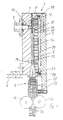
- the texturing nozzle consists of two rectangular halves 1 and 2 and an adjoining stowage chamber 3.
- the texturing nozzle and stowage chamber 3 are divided in a longitudinal plane 21.
- the left half of the nozzle 1 in FIG. 1 with the attached half of the storage chamber 3 is fastened in the machine frame 6.
- the nozzle half 2 and the half of the storage chamber 3 assigned to it can be moved perpendicular to the parting plane.
- the second nozzle half 2 consists of a guide body 4 and, as a functionally essential part: a piston 5.
- An elongated cylinder space 7 is incorporated into the guide body 4.
- the piston 5 is fitted into this cylinder space 7 in such a way that it is movable in the longitudinal direction.
- transverse grooves 15 are incorporated into the rear of the piston. The transverse grooves are so close together that a desired flexibility of the piston in the longitudinal direction is achieved.
- longitudinal grooves 16 can also be introduced into the rear of the piston, so that the piston also has a desired flexibility in the transverse direction.
- the piston is backed with a membrane 17 on its rear side facing the cylinder space 7.
- This is a thin plate, e.g. Metal plate, plastic plate, which is also very flexible.
- the shape of the membrane is also adapted to the shape of the cylinder space 7.
- the circumferential corner between the membrane 17 and the cylinder walls 7 is sealed by a frame-shaped sealing ring 18.
- the sealing ring 18 is held in its place by a holding frame 19, which is also adapted to the cross section of the cylinder space 7 with greater tolerance.
- the frame 19 has a groove, notch or the like on one of its circumferential corners, into which the frame-shaped seal 18 is inserted. However, the seal 18 projects beyond the periphery of the holding frame 19 in such a way that the seal rests on the walls of the cylinder space 7 and on the membrane 17.
- a pressure medium is applied to the cylinder space 7 through the connecting channel 20. It is preferably the heating medium that is also applied to the texturing nozzle.
- both the first nozzle half 1 and the piston 5 have a groove which forms the thread channel 12 in the closed state (cf. FIG. 2).
- the thread channel 12 can be acted upon by hot air connection 9, ring channel 10 and tap holes 11 with hot air.
- the openings of the ring channel 10 in the parting plane 21 of both the first nozzle half 1 and the piston 5 are close to one another in the closed state, so that hot air also flows into the piston.
- the stitch holes open into the thread channel at an acute angle.
- the hot air flowing into the thread channel on the one hand exerts an impulse on the running thread and on the other hand the thread is heated.
- the thread is compressed into a thread plug in the storage chamber.
- On the surface of the thread the hot air can escape through the slots 22 of the storage chamber.
- the thread plug 23 is transported by the conveyor wheels 24 at the end of the storage chamber.
- the movable half of the storage chamber 3 is attached to the piston 5. Therefore, the guide body 4 has a corresponding recess in the area of the passage of this storage chamber half.
- the guide body 4 has an extension 25. At the end of which there is a resilient support 26, which causes the two halves of the storage chamber 3 to lie tightly on one another and free of movement during operation.
- hot air duct 9 and the connecting duct 20 are connected to one another outside the texturing nozzle.
- the guide body 4 is moved in the direction of arrow 27 from the stationary first nozzle half.
- the supply of hot air to the connecting channel 20 is prevented, while the supply of hot air to the hot air connection 9 is maintained at reduced pressure.
- the second texturing nozzle half is moved back again, so that the first texturing nozzle half 1 and the piston 5 lie one on top of the other in the parting plane 21.
- the centering pins 13 in the piston 5, which have a conical tip, and the centering holes 14 in the first texturing nozzle half ensure that the piston 5 assumes its position during operation so that the two groove halves in the first texturing nozzle half and in the piston 5 close exactly cover the thread channel 12. It also ensures that the openings of the ring channel 10 in the parting plane 21 lie exactly on top of each other.
- the connecting duct 20 is now connected to the hot air source. As a result, the cylinder space 7 is pressurized.
- the pressure medium initially seals the sealing ring 18 with respect to the membrane 17 and the cylinder wall. Furthermore, the pressure medium presses the piston 5 firmly against the parting plane 21 of the first texturing nozzle half 1.
- the parting plane 21 of the piston 5 can conform well to the unevenness of the parting plane 21 of the first texturing nozzle half 1 under the pressure of the heating medium on its rear side. Even faults that e.g. occur by heating, are compensated by the soft piston 5.
- the sealing function is carried out independently of the piston by the membrane and the sealing ring.
- the piston geometry therefore has no adverse effect on the sealing function.
Landscapes
- Engineering & Computer Science (AREA)
- Mechanical Engineering (AREA)
- Textile Engineering (AREA)
- Yarns And Mechanical Finishing Of Yarns Or Ropes (AREA)
- Coating Apparatus (AREA)
- Closures For Containers (AREA)
Applications Claiming Priority (2)
| Application Number | Priority Date | Filing Date | Title |
|---|---|---|---|
| DE3627513 | 1986-08-13 | ||
| DE3627513A DE3627513C2 (de) | 1986-08-13 | 1986-08-13 | Düse zum Texturieren eines laufenden Fadens |
Publications (3)
| Publication Number | Publication Date |
|---|---|
| EP0256448A2 true EP0256448A2 (fr) | 1988-02-24 |
| EP0256448A3 EP0256448A3 (en) | 1990-07-25 |
| EP0256448B1 EP0256448B1 (fr) | 1993-01-07 |
Family
ID=6307337
Family Applications (1)
| Application Number | Title | Priority Date | Filing Date |
|---|---|---|---|
| EP87111461A Expired - Lifetime EP0256448B1 (fr) | 1986-08-13 | 1987-08-07 | Buse de texturation pour fil en mouvement |
Country Status (3)
| Country | Link |
|---|---|
| US (1) | US4829640A (fr) |
| EP (1) | EP0256448B1 (fr) |
| DE (2) | DE3627513C2 (fr) |
Cited By (4)
| Publication number | Priority date | Publication date | Assignee | Title |
|---|---|---|---|---|
| DE3915691A1 (de) * | 1988-05-18 | 1989-11-30 | Barmag Barmer Maschf | Texturierduese |
| EP0433217A1 (fr) * | 1989-12-14 | 1991-06-19 | Maschinenfabrik Rieter Ag | Chambre pour le traitement continu de filaments |
| US5469609A (en) * | 1993-07-15 | 1995-11-28 | Barmag Ag | Yarn texturing apparatus |
| DE4435923B4 (de) * | 1993-10-19 | 2008-01-24 | Oerlikon Textile Gmbh & Co. Kg | Vorrichtung und Verfahren zum gleichmäßigen Texturieren eines laufenden Fadens |
Families Citing this family (11)
| Publication number | Priority date | Publication date | Assignee | Title |
|---|---|---|---|---|
| DE3722773C1 (de) * | 1987-07-09 | 1989-01-12 | Hollingsworth Gmbh | Pneumatische Rohrfoerderanlage fuer Fasern |
| US5054173A (en) * | 1989-05-18 | 1991-10-08 | Barmag Ag | Method and apparatus for the enhanced crimping of multifilament yarn |
| RU2041981C1 (ru) * | 1989-11-11 | 1995-08-20 | Бармаг АГ | Фильера для текстурирования синтетической нити |
| EP0539808B1 (fr) * | 1991-10-26 | 1995-01-11 | Barmag Ag | Dispositif de frisage à boîte de bourrage pour filaments synthétiques |
| EP0957189A2 (fr) * | 1995-08-23 | 1999-11-17 | Maschinenfabrik Rieter Ag | Procédé et dispositif pour le frisage à boíte de bourrage de câbles de filaments synthétiques |
| US5976453A (en) * | 1998-06-29 | 1999-11-02 | Owens-Corning Sweden Ab | Device and process for expanding strand material |
| GB9902501D0 (en) * | 1999-02-05 | 1999-03-24 | Fibreguide Ltd | Air jet |
| DE50114368D1 (de) * | 2000-03-01 | 2008-11-13 | Oerlikon Textile Gmbh & Co Kg | Verfahren und vorrichtung zum stauchkräuseln |
| US8474115B2 (en) * | 2009-08-28 | 2013-07-02 | Ocv Intellectual Capital, Llc | Apparatus and method for making low tangle texturized roving |
| MX2020002237A (es) * | 2017-08-31 | 2020-07-20 | Ocv Intellectual Capital Llc | Aparato para texturizar material de hebra. |
| CN107829176B (zh) * | 2017-11-17 | 2019-12-03 | 武汉纺织大学 | 一种用于纱线超光洁处理的瓣合式装置的应用 |
Family Cites Families (12)
| Publication number | Priority date | Publication date | Assignee | Title |
|---|---|---|---|---|
| US3261071A (en) * | 1965-05-25 | 1966-07-19 | Du Pont | Yarn treating jet |
| US3324526A (en) * | 1965-05-26 | 1967-06-13 | Du Pont | Yarn treating jet |
| BE757346A (fr) * | 1969-10-10 | 1971-04-09 | Ici Ltd | Dispositif pneumatique servant a faire avancer une matiere filamentair |
| US4453298A (en) * | 1980-03-31 | 1984-06-12 | Rieter Machine Works, Ltd. | Construction of thread texturizing nozzles |
| EP0108205A1 (fr) * | 1982-10-12 | 1984-05-16 | Maschinenfabrik Rieter Ag | Tuyère de traitement de fil |
| EP0128208B1 (fr) * | 1982-12-18 | 1987-07-29 | B a r m a g AG | Chambre de chauffe pour fils continus |
| US4641504A (en) * | 1984-06-12 | 1987-02-10 | Barmag Barmer Maschinenfabrik Ag | Yarn heating chamber |
| DE3577733C5 (de) * | 1984-12-03 | 2010-12-30 | Maschinenfabrik Rieter Ag | Garnbehandlungsdüse. |
| DE3661740D1 (en) * | 1985-01-19 | 1989-02-16 | Barmag Barmer Maschf | Yarn texturing jet |
| CN1005199B (zh) * | 1985-01-19 | 1989-09-20 | 巴马格·巴默机器制造股份公司 | 丝传送和变形用的喷嘴 |
| GB2193232A (en) * | 1986-06-17 | 1988-02-03 | Rieter Ag Maschf | Thread treating nozzles |
| JPH06269866A (ja) * | 1993-03-24 | 1994-09-27 | Mazda Motor Corp | プレス成形装置 |
-
1986
- 1986-08-13 DE DE3627513A patent/DE3627513C2/de not_active Expired - Fee Related
-
1987
- 1987-08-07 EP EP87111461A patent/EP0256448B1/fr not_active Expired - Lifetime
- 1987-08-07 DE DE8787111461T patent/DE3783403D1/de not_active Expired - Fee Related
- 1987-08-13 US US07/084,920 patent/US4829640A/en not_active Expired - Fee Related
Cited By (5)
| Publication number | Priority date | Publication date | Assignee | Title |
|---|---|---|---|---|
| DE3915691A1 (de) * | 1988-05-18 | 1989-11-30 | Barmag Barmer Maschf | Texturierduese |
| EP0433217A1 (fr) * | 1989-12-14 | 1991-06-19 | Maschinenfabrik Rieter Ag | Chambre pour le traitement continu de filaments |
| US5136860A (en) * | 1989-12-14 | 1992-08-11 | Rieter Machine Works, Ltd. | Chamber for the continuous treatment of filaments |
| US5469609A (en) * | 1993-07-15 | 1995-11-28 | Barmag Ag | Yarn texturing apparatus |
| DE4435923B4 (de) * | 1993-10-19 | 2008-01-24 | Oerlikon Textile Gmbh & Co. Kg | Vorrichtung und Verfahren zum gleichmäßigen Texturieren eines laufenden Fadens |
Also Published As
| Publication number | Publication date |
|---|---|
| DE3627513C2 (de) | 1996-09-19 |
| DE3627513A1 (de) | 1988-02-18 |
| EP0256448B1 (fr) | 1993-01-07 |
| DE3783403D1 (de) | 1993-02-18 |
| EP0256448A3 (en) | 1990-07-25 |
| US4829640A (en) | 1989-05-16 |
Similar Documents
| Publication | Publication Date | Title |
|---|---|---|
| EP0256448B1 (fr) | Buse de texturation pour fil en mouvement | |
| DE69810362T2 (de) | Dichtverbindung zwischen Fluidbohrungen | |
| DE69918851T2 (de) | Vorrichtung zur abschottung oder prüfung eines rohrabschnitts | |
| DE2313983A1 (de) | In eine fluidleitung einschaltbare kupplungseinrichtung zur aufnahme mindestens einer beeinflussungsvorrichtung fuer das fluid | |
| DE69511345T2 (de) | Dichtung für eine Ventileinheit | |
| EP1528129B1 (fr) | Procédé et dispositif pour le traitement de fils en mouvement avec une substance gazeuse ou vaporeuse | |
| DE2544879A1 (de) | Mehrteiliger verteilerkopf zur ueberfuehrung eines kunstharzes von einer kunstharzquelle zu mehreren spritzgiessduesen | |
| DE3532499C1 (de) | Vorrichtung zum hydraulischen Aufweiten von Rohrabschnitten | |
| DE1479560C3 (de) | Verfahren zum Herstellen eines ein Kanalsystem enthaltenden Verbundkörpers, insbesondere eines Wärmetauschers | |
| DE2134137C3 (de) | Einspannvorrichtung fur ein Innen Trennsageblatt | |
| DE2254383A1 (de) | Dichtungselement | |
| EP3850684B1 (fr) | Dispositif d'étanchéité pour l'étanchéification d'une partie de cadre | |
| DE19725999C1 (de) | Steckverbindungseinrichtung sowie mit einer oder mehreren Steckverbindungseinrichtungen ausgestattete Fluidverteilereinrichtung | |
| DE3405743A1 (de) | Vorrichtung zum greifen von bauteilen | |
| DE19516980C1 (de) | Ventil, insbesondere Kühlmittelventil für Werkzeugrevolver | |
| DE1804640B1 (de) | Spritzkopf zur Herstellung von Kunststoffrohren oder -schlaeuchen | |
| DE8524858U1 (de) | Doppeltellerventil | |
| DE3915691C2 (de) | Verfahren zur Stauchkammertexturierung und Vorrichtung zur Druchführung des Verfahrens | |
| DE2523667A1 (de) | Ventil, insbesondere pneumatisches verzoegerungsventil | |
| DE19743185A1 (de) | Vorrichtung zum Anschließen von Rohrleitungen | |
| DE3734987C1 (de) | Schneidrotor mit auswechselbaren Messerleisten zum Zerkleinern von festen Materialien | |
| EP0941799B1 (fr) | Joint d'étanchéité tubulaire linéaire et dispositif de serrage à vide | |
| DE2759141A1 (de) | Integraldichtung | |
| DE2357608A1 (de) | Vorrichtung zum filtern von weichem material | |
| DE19642263A1 (de) | Dichtverschluß |
Legal Events
| Date | Code | Title | Description |
|---|---|---|---|
| PUAI | Public reference made under article 153(3) epc to a published international application that has entered the european phase |
Free format text: ORIGINAL CODE: 0009012 |
|
| AK | Designated contracting states |
Kind code of ref document: A2 Designated state(s): BE CH DE FR GB IT LI |
|
| PUAL | Search report despatched |
Free format text: ORIGINAL CODE: 0009013 |
|
| AK | Designated contracting states |
Kind code of ref document: A3 Designated state(s): BE CH DE FR GB IT LI |
|
| 17P | Request for examination filed |
Effective date: 19900616 |
|
| 17Q | First examination report despatched |
Effective date: 19920120 |
|
| ITF | It: translation for a ep patent filed | ||
| GRAA | (expected) grant |
Free format text: ORIGINAL CODE: 0009210 |
|
| AK | Designated contracting states |
Kind code of ref document: B1 Designated state(s): BE CH DE FR GB IT LI |
|
| REF | Corresponds to: |
Ref document number: 3783403 Country of ref document: DE Date of ref document: 19930218 |
|
| GBT | Gb: translation of ep patent filed (gb section 77(6)(a)/1977) |
Effective date: 19930209 |
|
| ET | Fr: translation filed | ||
| PLBE | No opposition filed within time limit |
Free format text: ORIGINAL CODE: 0009261 |
|
| STAA | Information on the status of an ep patent application or granted ep patent |
Free format text: STATUS: NO OPPOSITION FILED WITHIN TIME LIMIT |
|
| 26N | No opposition filed | ||
| PGFP | Annual fee paid to national office [announced via postgrant information from national office to epo] |
Ref country code: FR Payment date: 19950720 Year of fee payment: 9 |
|
| PGFP | Annual fee paid to national office [announced via postgrant information from national office to epo] |
Ref country code: GB Payment date: 19950727 Year of fee payment: 9 |
|
| PGFP | Annual fee paid to national office [announced via postgrant information from national office to epo] |
Ref country code: DE Payment date: 19950831 Year of fee payment: 9 Ref country code: CH Payment date: 19950831 Year of fee payment: 9 |
|
| PGFP | Annual fee paid to national office [announced via postgrant information from national office to epo] |
Ref country code: BE Payment date: 19951004 Year of fee payment: 9 |
|
| PG25 | Lapsed in a contracting state [announced via postgrant information from national office to epo] |
Ref country code: GB Effective date: 19960807 |
|
| PG25 | Lapsed in a contracting state [announced via postgrant information from national office to epo] |
Ref country code: LI Effective date: 19960831 Ref country code: CH Effective date: 19960831 Ref country code: BE Effective date: 19960831 |
|
| BERE | Be: lapsed |
Owner name: BARMAG A.G. Effective date: 19960831 |
|
| GBPC | Gb: european patent ceased through non-payment of renewal fee |
Effective date: 19960807 |
|
| REG | Reference to a national code |
Ref country code: CH Ref legal event code: PL |
|
| PG25 | Lapsed in a contracting state [announced via postgrant information from national office to epo] |
Ref country code: FR Effective date: 19970430 |
|
| PG25 | Lapsed in a contracting state [announced via postgrant information from national office to epo] |
Ref country code: DE Effective date: 19970501 |
|
| REG | Reference to a national code |
Ref country code: FR Ref legal event code: ST |
|
| PG25 | Lapsed in a contracting state [announced via postgrant information from national office to epo] |
Ref country code: IT Free format text: LAPSE BECAUSE OF NON-PAYMENT OF DUE FEES;WARNING: LAPSES OF ITALIAN PATENTS WITH EFFECTIVE DATE BEFORE 2007 MAY HAVE OCCURRED AT ANY TIME BEFORE 2007. THE CORRECT EFFECTIVE DATE MAY BE DIFFERENT FROM THE ONE RECORDED. Effective date: 20050807 |