EP0256683A2 - Mittel zum Aufrollen eines Ballons eines Ballonkatheters - Google Patents
Mittel zum Aufrollen eines Ballons eines Ballonkatheters Download PDFInfo
- Publication number
- EP0256683A2 EP0256683A2 EP87306467A EP87306467A EP0256683A2 EP 0256683 A2 EP0256683 A2 EP 0256683A2 EP 87306467 A EP87306467 A EP 87306467A EP 87306467 A EP87306467 A EP 87306467A EP 0256683 A2 EP0256683 A2 EP 0256683A2
- Authority
- EP
- European Patent Office
- Prior art keywords
- balloon
- furling
- catheter
- deflated
- furled
- Prior art date
- Legal status (The legal status is an assumption and is not a legal conclusion. Google has not performed a legal analysis and makes no representation as to the accuracy of the status listed.)
- Withdrawn
Links
Images

Classifications
-
- A—HUMAN NECESSITIES
- A61—MEDICAL OR VETERINARY SCIENCE; HYGIENE
- A61M—DEVICES FOR INTRODUCING MEDIA INTO, OR ONTO, THE BODY; DEVICES FOR TRANSDUCING BODY MEDIA OR FOR TAKING MEDIA FROM THE BODY; DEVICES FOR PRODUCING OR ENDING SLEEP OR STUPOR
- A61M5/00—Devices for bringing media into the body in a subcutaneous, intra-vascular or intramuscular way; Accessories therefor, e.g. filling or cleaning devices, arm-rests
- A61M5/002—Packages specially adapted therefor, e.g. for syringes or needles, kits for diabetics
-
- A—HUMAN NECESSITIES
- A61—MEDICAL OR VETERINARY SCIENCE; HYGIENE
- A61M—DEVICES FOR INTRODUCING MEDIA INTO, OR ONTO, THE BODY; DEVICES FOR TRANSDUCING BODY MEDIA OR FOR TAKING MEDIA FROM THE BODY; DEVICES FOR PRODUCING OR ENDING SLEEP OR STUPOR
- A61M25/00—Catheters; Hollow probes
- A61M25/002—Packages specially adapted therefor ; catheter kit packages
-
- A—HUMAN NECESSITIES
- A61—MEDICAL OR VETERINARY SCIENCE; HYGIENE
- A61M—DEVICES FOR INTRODUCING MEDIA INTO, OR ONTO, THE BODY; DEVICES FOR TRANSDUCING BODY MEDIA OR FOR TAKING MEDIA FROM THE BODY; DEVICES FOR PRODUCING OR ENDING SLEEP OR STUPOR
- A61M60/00—Blood pumps; Devices for mechanical circulatory actuation; Balloon pumps for circulatory assistance
- A61M60/10—Location thereof with respect to the patient's body
- A61M60/122—Implantable pumps or pumping devices, i.e. the blood being pumped inside the patient's body
- A61M60/126—Implantable pumps or pumping devices, i.e. the blood being pumped inside the patient's body implantable via, into, inside, in line, branching on, or around a blood vessel
- A61M60/13—Implantable pumps or pumping devices, i.e. the blood being pumped inside the patient's body implantable via, into, inside, in line, branching on, or around a blood vessel by means of a catheter allowing explantation, e.g. catheter pumps temporarily introduced via the vascular system
-
- A—HUMAN NECESSITIES
- A61—MEDICAL OR VETERINARY SCIENCE; HYGIENE
- A61M—DEVICES FOR INTRODUCING MEDIA INTO, OR ONTO, THE BODY; DEVICES FOR TRANSDUCING BODY MEDIA OR FOR TAKING MEDIA FROM THE BODY; DEVICES FOR PRODUCING OR ENDING SLEEP OR STUPOR
- A61M60/00—Blood pumps; Devices for mechanical circulatory actuation; Balloon pumps for circulatory assistance
- A61M60/10—Location thereof with respect to the patient's body
- A61M60/122—Implantable pumps or pumping devices, i.e. the blood being pumped inside the patient's body
- A61M60/126—Implantable pumps or pumping devices, i.e. the blood being pumped inside the patient's body implantable via, into, inside, in line, branching on, or around a blood vessel
- A61M60/135—Implantable pumps or pumping devices, i.e. the blood being pumped inside the patient's body implantable via, into, inside, in line, branching on, or around a blood vessel inside a blood vessel, e.g. using grafting
- A61M60/139—Implantable pumps or pumping devices, i.e. the blood being pumped inside the patient's body implantable via, into, inside, in line, branching on, or around a blood vessel inside a blood vessel, e.g. using grafting inside the aorta, e.g. intra-aortic balloon pumps
-
- A—HUMAN NECESSITIES
- A61—MEDICAL OR VETERINARY SCIENCE; HYGIENE
- A61M—DEVICES FOR INTRODUCING MEDIA INTO, OR ONTO, THE BODY; DEVICES FOR TRANSDUCING BODY MEDIA OR FOR TAKING MEDIA FROM THE BODY; DEVICES FOR PRODUCING OR ENDING SLEEP OR STUPOR
- A61M60/00—Blood pumps; Devices for mechanical circulatory actuation; Balloon pumps for circulatory assistance
- A61M60/20—Type thereof
- A61M60/295—Balloon pumps for circulatory assistance
-
- A—HUMAN NECESSITIES
- A61—MEDICAL OR VETERINARY SCIENCE; HYGIENE
- A61M—DEVICES FOR INTRODUCING MEDIA INTO, OR ONTO, THE BODY; DEVICES FOR TRANSDUCING BODY MEDIA OR FOR TAKING MEDIA FROM THE BODY; DEVICES FOR PRODUCING OR ENDING SLEEP OR STUPOR
- A61M60/00—Blood pumps; Devices for mechanical circulatory actuation; Balloon pumps for circulatory assistance
- A61M60/40—Details relating to driving
- A61M60/497—Details relating to driving for balloon pumps for circulatory assistance
-
- A—HUMAN NECESSITIES
- A61—MEDICAL OR VETERINARY SCIENCE; HYGIENE
- A61M—DEVICES FOR INTRODUCING MEDIA INTO, OR ONTO, THE BODY; DEVICES FOR TRANSDUCING BODY MEDIA OR FOR TAKING MEDIA FROM THE BODY; DEVICES FOR PRODUCING OR ENDING SLEEP OR STUPOR
- A61M60/00—Blood pumps; Devices for mechanical circulatory actuation; Balloon pumps for circulatory assistance
- A61M60/80—Constructional details other than related to driving
- A61M60/841—Constructional details other than related to driving of balloon pumps for circulatory assistance
- A61M60/843—Balloon aspects, e.g. shapes or materials
-
- A—HUMAN NECESSITIES
- A61—MEDICAL OR VETERINARY SCIENCE; HYGIENE
- A61M—DEVICES FOR INTRODUCING MEDIA INTO, OR ONTO, THE BODY; DEVICES FOR TRANSDUCING BODY MEDIA OR FOR TAKING MEDIA FROM THE BODY; DEVICES FOR PRODUCING OR ENDING SLEEP OR STUPOR
- A61M2209/00—Ancillary equipment
- A61M2209/06—Packaging for specific medical equipment
-
- A—HUMAN NECESSITIES
- A61—MEDICAL OR VETERINARY SCIENCE; HYGIENE
- A61M—DEVICES FOR INTRODUCING MEDIA INTO, OR ONTO, THE BODY; DEVICES FOR TRANSDUCING BODY MEDIA OR FOR TAKING MEDIA FROM THE BODY; DEVICES FOR PRODUCING OR ENDING SLEEP OR STUPOR
- A61M60/00—Blood pumps; Devices for mechanical circulatory actuation; Balloon pumps for circulatory assistance
- A61M60/20—Type thereof
- A61M60/247—Positive displacement blood pumps
- A61M60/253—Positive displacement blood pumps including a displacement member directly acting on the blood
- A61M60/268—Positive displacement blood pumps including a displacement member directly acting on the blood the displacement member being flexible, e.g. membranes, diaphragms or bladders
- A61M60/274—Positive displacement blood pumps including a displacement member directly acting on the blood the displacement member being flexible, e.g. membranes, diaphragms or bladders the inlet and outlet being the same, e.g. para-aortic counter-pulsation blood pumps
Definitions
- This invention relates to balloon catheters such as the intra-aortic balloon (IAB) catheter, and particularly to methods for wrapping the balloon prior to insertion into a patient.
- IAB intra-aortic balloon
- Intra-aortic balloon counterpulsation has been in use widely for several years. Several attempts have been made over the years to improve IAB catheters and insertion techniques in order to enable safer and more rapid insertion so that the IAB can be more effectively used.
- the balloon was wrapped or furled by hand by rolling the two balloon flaps around the central support. Although the tightness of this roll correlated with the ease of insertion, the furling was inconsistent.
- a structure for furling a deflated, generally flat balloon of a balloon catheter and confining at least a portion thereof within a sheath preparatory to use comprising relatively rotatable means engaged with the ends of the deflated balloon and with the balloon intermediate its ends, said means being relatively rotatable to furl the balloon about its longitudinal axis in opposite directions with respect to its mid-length to contract the deflated balloon to a less than predetermined diameter from end-to-end, a sheath defining an elongate tubular passage corresponding in internal diameter to the outside diameter of the furled balloon, said sheath supported in axial alignment with the furled balloon, and means for effecting movement of a portion at least of the furled balloon into said sheath to constrain the furled balloon in said furled condition.
- the invention provides a packaged, deflated balloon catheter, including a catheter connected at its distal end to the proximal end of a balloon, a check valve connected to the proximal end of the catheter and a wire connected at its proximal end to the proximal end of the catheter end and its distal end to the distal end of the balloon, said package comprising a tray containing a recess for receiving the deflated balloon, catheter and check valve, a furling device non-rotatably disposed in the recess about the deflated balloon and a holding sheath disposed in the recess adjacent the furling device, said catheter and wire being relatively rotatable with respect to the mid-section of said balloon and to the furling device to furl the balloon within the furling device from its ends towards its mid-section.
- the invention provides a furling fixture for furling a deflated balloon of a balloon catheter, said fixture comprising an elongate retaining structure defining a recess for retaining structure defining a recess corresponding substantially in width to the width of the deflated balloon and in minimum depth to substantially the thickness of the deflated balloon, said fixture being operable when rotated relative to the ends of the balloon catheter to furl the balloon from its mid-length to its ends to no greater than a predetermined diameter from end to end.
- the invention provides a method of preparing a balloon catheter for insertion into a patient, said method compriivelysing evacuating the balloon to cause it to become flattened throughout its length from end-to-end and to eliminate air pockets, furling the flattened balloon about its longitudinal axis commencing at its mid-length and proceeding to its opposite ends to condense the balloon to a predetermined diameter from end-to-end and confining the furled, condensed balloon within a tubular sheath of an inside diameter corresponding to substantially the predetermined diameter of the furled balloon, wherein said furling step is accomplished prior to removing the balloon catheter from a tray by using a furling fixture disposed within said tray, said fixtures comprising means for retaining the opposite broad faces of the deflated balloon in a substantially flat position at opposite sides of the longitudinal axis, said means being operable to effect rotation of the balloon at opposite sides of its longitudinal axis relative to its longitudinal axis and simultaneously to relinquish the balloon at opposite
- an apparatus embodying aspects of the invention includes means for effecting rotation of a deflated balloon of a balloon catheter intermediate its ends relative to its ends to furl the balloon in opposite directions from its mid-length to its ends to a predetermined diameter, means for evacuating the balloon and means for receiving and retaining the furled evacuated balloon preparatory to use.
- the means for effecting furling may comprise a furling device in which the deflated balloon is disposed intermediate its ends, a catheter connected at one end to one end of the balloon, a stiff wire (i.e. a guide or stylet wire which is used to insert the IAB into a patient and then removed) connected at one end to the distal end of the balloon and means for rotating the catheter and wire in unison relative to the furling device.
- the furling device may comprise a structure embodying a recess defined by spaced, parallel surface of a transverse width corresponding substantially to the width of the deflated balloon and in minimum depth to the thickness of the deflated balloon medially of which there is a groove of a cross section corresponding to the desired furled diameter of the balloon.
- the means for receiving and retaining the furled balloon comprises a sheath consisting of a tube-like structure having an inner diameter at least equal to the diameter of the furled balloon.
- the sheath comprises confronting structures articulated along one longitudinal side and detachably interengaged along their other sides, said structures containing in their confronting sides longitudinal grooves of half circular cross section which collectively define a longitudinal groove of circular cross section.
- the invention may further provide a package structure comprising a recessed tray within which is disposed the deflated balloon, the catheter, the coupling and a syringe together with the furling device positioned about the deflated balloon and the retaining sheath disposed about the catheter.
- a cover is removably applied to the tray and, when removed, enables access to the syringe and coupling for evacuating the balloon, furling the balloon and withdrawing the furled balloon into the retaining sheath.
- a preferred method in accordance with the invention comprises the steps of evacuating the balloon and, furling the evacuated balloon from its mid-length in opposite directions to its opposite ends by means of a furling device and drawing the furled balloon into a retaining sheath.
- Furling may be achieved by supporting the furled balloon between opposed friction-engendering surfaces, longitudinally of which there is a groove corresponding in cross section to the diameter of the furled balloon and rotating the ends of the balloon in a direction to contract the balloon from the friction-engendering surfaces into the groove.
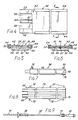
- a percutaneous balloon 10 a balloon catheter 12 connected at one end to one end of the balloon, a wire 14 connected at one end to the other end of the balloon and extending longitudinally through the balloon and through the catheter and a coupling 16 connecting the other end of the catheter to the other end of the wire.
- the coupling 16 is for connecting the catheter and, hence, the balloon to a syringe 18 or vacuum pump (not shown) for the purpose of evacuating the balloon and is desirably provided with a check valve 20 for maintaining the vacuum once the balloon has been evacuated.
- the coupling 16 further provides for connecting the catheter and balloon to one end of a tube, the other end of which may be connected to a diastolic pump, not shown, for the purpose of alternately inflating and deflating the balloon after it is inserted into a patient.
- a package 24, FIG. 3, for the aforesaid structure in the form of a tray 26 which is designed to contain the structure prior to use with the balloon deflated and to provide for furling the balloon incident to its use. It is a purpose of this invention to package the balloon in such a way as to eliminate the disadvantage of a pre-furled balloon which, if furled for any length of time within the package, can resist unfurling, and which retains crease lines after unfurling which tend to obstruct flow and cause incomplete expansion. It is also a purpose of this invention to provide a means for conventionally furling an IAB balloon so that once inserted into a patient, it automatically unfurls, having no twists in the balloon that could cause coagulation.
- the package comprises a tray 26 of elongate, generally rectangular configuration containing longitudinally thereof recesses comprising a first recess 28, a second recess 30, a third recess 32 and a fourth recess 34.
- the first recess 28 is dimensioned to receive the deflated balloon and a furling device 36.
- the second recess 30 is dimensioned to receive a holding sheath 38, the third recess 32 is designed to receive the coupling 16 and the fourth recess is designed to receive the syringe 18.
- the second and third recesses 30 and 32 in combination are long enough to accommodate the catheter tube 12.
- the furling device 36 as shown in FIGS. 1, 4, 5 and 6 is an elongate structure of generally rectangular configuration comprised of two parts, a bottom part 40, a top part 42 and connectors 44-44 for detachably securing them to each other.
- the bottom part 40 comprises an elongate block 46 having top and bottom surfaces 48 and 50 and spaced, parallel, longitudinal edge flanges 52-52.
- the top surface 48 contains longitudinally thereof a shallow recess 58 of a width corresponding substantially to the width of a deflated balloon and a depth greater than the thickness of the deflated balloon.
- a groove 60 extends longitudinally of the recess midway between its opposite sides of a cross section corresponding substantially to the desired diameter or cross section of the furled balloon.
- the top part 42 comprises a flat plate corresponding in length and width to the bottom part.
- the top and bottom parts are removably held engaged by the connectors 44-44 which are slidably engaged with the flanges 52-52 and the opposite edges of the top part 42.
- block 46 can be formed to include connectors 44-44 as an integral part thereof.
- the holding sheath 38 is in the form of a split tube comprising two parts 66-66 disposed in adjacency such as to define a longitudinal passage 68 of a diameter to receive the furled balloon.
- the holding sheath 38 fits within the second recess 30 with one end adjacent the first recess 28 and the other end adjacent the third recess 32.
- other forms of a sheath such as, for example, a splittable sheath, can be used.
- a splittable sheath as a tube having one or more pre-scored lines along the longitudinal dimension so that the sheath can be easily split and removed after its function has been performed.
- the sheath is at least long enough to cover one end and the mid-section of the furled balloon to prevent the balloon from unfurling prior to insertion into the patient.
- the third recess 32 is long enough and deep enough to accommodate the catheter 12.
- the fourth recess 34 is of a length and depth to receive the coupling 16 and the syringe 18.
- an elongate recess 35 Peripherally of the aforesaid recesses is an elongate recess 35, FIG. 3, comprising spaced, parallel lengths extending longitudinally of the tray, the ends of which are joined by half-circular lengths for conveniently receiving a tube 22 for connecting the IAB device to a diastolic pump.
- the balloon, catheter, coupling, syringe and tube are disposed in the tray 26 and a cover sheet 74 is applied to the top side to form a sealed package.
- the balloon is deflated and loosely enough contained in the furling fixture 36 so that there is no possibility of the walls of the balloon becoming creased and/or adhered to each other.
- the cover sheet 74 When ready for use, the cover sheet 74 is removed, the balloon is evacuated by attaching the syringe 18 to the coupling 16 and pulling back on the plunger to create a vacuum, whereupon the syringe 18 is detached and the coupling 16 grasped and rotated.
- a vacutainer or other means can be used to evacuate he balloon prior to furling. Since one end of the deflated balloon 10 is fixed to the wire 14 and the other end to the catheter 12, rotation of the wire and catheter in unison relative to the furling device 36 which is held stationary furls the balloon. In contrast to prior practice and devices for furling balloons, the furling extends from the mid-length of the balloon toward its opposite ends rather than from one end to the other, as illustrated in FIG.
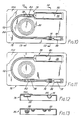
- the furled balloon is withdrawn from the furling device 36 longitudinally into the open end of the holding sheath 38 to an extent to constrain approximately half of the length of the furled balloon, FIG. 9, whereupon the furled balloon is inserted and, as it is moved into place, the holding sheath 38 is removed from the balloon and subsequently preferably removed from the catheter.
- FIG. 10 to 13 a second form of package is provided, FIGS. 10 to 13, of approximately half the length and twice the width of the first package and again is in the form of a tray.
- the tray 76 as shown in FIGS. 10 to 13 has generally spaced, parallel sides and ends.
- Recesses 80, 82, 84 and 86 extend continuously from the one end along one side around the other end and back along the other side.
- the recess 80 is of generally rectangular configuration corresponding substantially in length and depth to the furling device 36.
- the recess 82 is dimensioned to receive the holding sheath 38.
- the recesses 84 and 86 are dimensioned to receivethe catheter 12, coupling 16 and syringe 18.
- the recess 82 can be located at the opposite side from the recess 80 in line with the recess 86.
- the balloon 10 is positioned in the first recess 80 in a deflated condition enclosed within the furling device 36.
- the sheath 38 is positioned in the recess 82 and the catheter tube, valve and pump in the remaining recesses.
- a cover sheet 100 is applied over the top of the tray. As thus packaged, the balloon is deflated and held in an uncompressed condition.
- the cover sheet 100 is stripped from the tray and the syringe 18 is connected to the coupling 16 to withdraw air from the balloon, whereupon the coupling 16 is rotated to furl the balloon.
- Rotation of the coupling 16 rotates the ends of the balloon relative to the portion thereof between the ends.
- Furling is continued until the furled balloon seats in the groove 60, whereupon the furled balloon is drawn into the sheath 38 to at least its mid-length, FIG. 9.
- the furled balloon can then be inserted and connected in the usual manner by way of a flexible tube to a diastolic pump.
- the flexible tube can be conveniently stored in recess 86, FIG. 10.
- the coupling 16, as aforesaid preferably embodies a check valve so that when the syringe 18 is detached, the vacuum will be maintained in the balloon.
- the trays 26,73 thus described are formed of a flexible plastic and, desirably, at least the cover is comprised of transparent plastic so as to enable easily assessing the kind or content of apparatus sealed therein.
- the apparatus and method for furling balloon catheters described above lessen the likelihood of over-wrap encountered with prior art mechanically wrapped balloon catheters.
- the use of furled balloons in accordance with the present invention helps to reduce questionable unwrapping of the balloon once inserted into the patient.
- balloons furled in accordance with this invention can have a carefully controlled diameter to pass through a smaller percutaneous introducer sheath, thereby permitting improved blood flow.
- the balloon should not be over-furled because the balloon will rotate freely within the groove of the furling device.
- the invention also includes furling the balloon of double lumen balloon catheters which can be accomplished in a similar manner.
Landscapes
- Health & Medical Sciences (AREA)
- Heart & Thoracic Surgery (AREA)
- Engineering & Computer Science (AREA)
- Cardiology (AREA)
- Life Sciences & Earth Sciences (AREA)
- Biomedical Technology (AREA)
- Hematology (AREA)
- Animal Behavior & Ethology (AREA)
- General Health & Medical Sciences (AREA)
- Public Health (AREA)
- Veterinary Medicine (AREA)
- Anesthesiology (AREA)
- Mechanical Engineering (AREA)
- Vascular Medicine (AREA)
- Geometry (AREA)
- Diabetes (AREA)
- Physics & Mathematics (AREA)
- Transplantation (AREA)
- Pulmonology (AREA)
- Biophysics (AREA)
- Media Introduction/Drainage Providing Device (AREA)
- Infusion, Injection, And Reservoir Apparatuses (AREA)
Applications Claiming Priority (2)
| Application Number | Priority Date | Filing Date | Title |
|---|---|---|---|
| US89335486A | 1986-08-04 | 1986-08-04 | |
| US893354 | 1986-08-04 |
Publications (2)
| Publication Number | Publication Date |
|---|---|
| EP0256683A2 true EP0256683A2 (de) | 1988-02-24 |
| EP0256683A3 EP0256683A3 (de) | 1989-08-09 |
Family
ID=25401422
Family Applications (1)
| Application Number | Title | Priority Date | Filing Date |
|---|---|---|---|
| EP87306467A Withdrawn EP0256683A3 (de) | 1986-08-04 | 1987-07-22 | Mittel zum Aufrollen eines Ballons eines Ballonkatheters |
Country Status (2)
| Country | Link |
|---|---|
| EP (1) | EP0256683A3 (de) |
| JP (1) | JPS6399878A (de) |
Cited By (21)
| Publication number | Priority date | Publication date | Assignee | Title |
|---|---|---|---|---|
| US5015230A (en) * | 1989-01-30 | 1991-05-14 | Vas-Cath Incorporated | Angioplasty catheter with spiral balloon |
| AU621008B2 (en) * | 1989-09-25 | 1992-02-27 | Schneider (Usa) Inc. | Small diameter dilatation catheter having wire reinforced coaxial tubular body |
| WO1999051167A3 (en) * | 1998-04-02 | 1999-12-23 | Salviac Ltd | Delivery catheter |
| US6432122B1 (en) | 1997-11-07 | 2002-08-13 | Salviac Limited | Embolic protection device |
| US6565591B2 (en) | 2000-06-23 | 2003-05-20 | Salviac Limited | Medical device |
| US6726701B2 (en) | 1999-05-07 | 2004-04-27 | Salviac Limited | Embolic protection device |
| US6887256B2 (en) | 1997-11-07 | 2005-05-03 | Salviac Limited | Embolic protection system |
| US6918921B2 (en) | 1999-05-07 | 2005-07-19 | Salviac Limited | Support frame for an embolic protection device |
| US6964672B2 (en) | 1999-05-07 | 2005-11-15 | Salviac Limited | Support frame for an embolic protection device |
| US7014647B2 (en) | 1999-05-07 | 2006-03-21 | Salviac Limited | Support frame for an embolic protection device |
| US7037320B2 (en) | 2001-12-21 | 2006-05-02 | Salviac Limited | Support frame for an embolic protection device |
| US7144408B2 (en) | 2002-03-05 | 2006-12-05 | Salviac Limited | Embolic protection system |
| US7491215B2 (en) | 1999-05-07 | 2009-02-17 | Salviac Limited | Filter element for embolic protection device |
| US7491216B2 (en) | 1997-11-07 | 2009-02-17 | Salviac Limited | Filter element with retractable guidewire tip |
| US7819893B2 (en) | 2000-06-23 | 2010-10-26 | Salviac Limited | Medical device |
| US8231565B2 (en) | 2002-06-14 | 2012-07-31 | Mcneil-Ppc, Inc. | Applicator device for medicated materials |
| WO2016016883A1 (en) * | 2014-07-28 | 2016-02-04 | Smart Medical Systems Ltd. | Controlled furling balloon assembly |
| WO2025141457A1 (en) * | 2023-12-28 | 2025-07-03 | Magenta Medical Ltd | Packaging for blood pumps |
| US12453848B2 (en) | 2019-01-24 | 2025-10-28 | Magenta Medical Ltd. | Distal tip element for a ventricular assist device |
| US12544556B2 (en) | 2021-03-09 | 2026-02-10 | Magenta Medical Ltd | Blood pump housing |
| US12544554B2 (en) | 2022-09-14 | 2026-02-10 | Magenta Medical Ltd | Impeller blades |
Families Citing this family (3)
| Publication number | Priority date | Publication date | Assignee | Title |
|---|---|---|---|---|
| US7104968B2 (en) * | 2002-06-14 | 2006-09-12 | Mcneil-Ppc, Inc. | Applicator device for suppositories and the like |
| US9038822B2 (en) * | 2013-03-15 | 2015-05-26 | Medtronic Vascular, Inc. | Blow-molded package for a catheter |
| CN108464877B (zh) * | 2018-03-05 | 2020-11-06 | 金仕生物科技(常熟)有限公司 | 经导管心脏瓣膜预装系统及预装方法 |
Family Cites Families (4)
| Publication number | Priority date | Publication date | Assignee | Title |
|---|---|---|---|---|
| US4292974A (en) * | 1980-01-30 | 1981-10-06 | Thomas J. Fogarty | Dilatation catheter apparatus and method |
| US4531512A (en) * | 1981-06-15 | 1985-07-30 | Datascope Corporation | Wrapping system for intra-aortic balloon utilizing a wrapping envelope |
| US4681092A (en) * | 1985-05-21 | 1987-07-21 | Kontron Inc. | Balloon catheter wrapping apparatus |
| EP0228787A1 (de) * | 1985-11-08 | 1987-07-15 | Datascope Corp. | Vorgefalteter Ballonkatheter |
-
1987
- 1987-07-22 EP EP87306467A patent/EP0256683A3/de not_active Withdrawn
- 1987-08-03 JP JP62194267A patent/JPS6399878A/ja active Pending
Cited By (55)
| Publication number | Priority date | Publication date | Assignee | Title |
|---|---|---|---|---|
| US5015230A (en) * | 1989-01-30 | 1991-05-14 | Vas-Cath Incorporated | Angioplasty catheter with spiral balloon |
| AU621008B2 (en) * | 1989-09-25 | 1992-02-27 | Schneider (Usa) Inc. | Small diameter dilatation catheter having wire reinforced coaxial tubular body |
| US8221448B2 (en) | 1997-11-07 | 2012-07-17 | Salviac Limited | Embolic protection device |
| US7833242B2 (en) | 1997-11-07 | 2010-11-16 | Salviac Limited | Embolic protection device |
| US7901427B2 (en) | 1997-11-07 | 2011-03-08 | Salviac Limited | Filter element with retractable guidewire tip |
| US6645224B2 (en) | 1997-11-07 | 2003-11-11 | Salviac Limited | Embolic protection device |
| US8852226B2 (en) | 1997-11-07 | 2014-10-07 | Salviac Limited | Vascular device for use during an interventional procedure |
| US8603131B2 (en) | 1997-11-07 | 2013-12-10 | Salviac Limited | Embolic protection device |
| US6887256B2 (en) | 1997-11-07 | 2005-05-03 | Salviac Limited | Embolic protection system |
| US8430901B2 (en) | 1997-11-07 | 2013-04-30 | Salviac Limited | Embolic protection device |
| US8328842B2 (en) | 1997-11-07 | 2012-12-11 | Salviac Limited | Filter element with retractable guidewire tip |
| US8241319B2 (en) | 1997-11-07 | 2012-08-14 | Salviac Limited | Embolic protection system |
| US8226678B2 (en) | 1997-11-07 | 2012-07-24 | Salviac Limited | Embolic protection device |
| US8216270B2 (en) | 1997-11-07 | 2012-07-10 | Salviac Limited | Embolic protection device |
| US8123776B2 (en) | 1997-11-07 | 2012-02-28 | Salviac Limited | Embolic protection system |
| US8057504B2 (en) | 1997-11-07 | 2011-11-15 | Salviac Limited | Embolic protection device |
| US7491216B2 (en) | 1997-11-07 | 2009-02-17 | Salviac Limited | Filter element with retractable guidewire tip |
| US7510565B2 (en) | 1997-11-07 | 2009-03-31 | Salviac Limited | Embolic protection device |
| US7662165B2 (en) | 1997-11-07 | 2010-02-16 | Salviac Limited | Embolic protection device |
| US7780697B2 (en) | 1997-11-07 | 2010-08-24 | Salviac Limited | Embolic protection system |
| US7785342B2 (en) | 1997-11-07 | 2010-08-31 | Salviac Limited | Embolic protection device |
| US8052716B2 (en) | 1997-11-07 | 2011-11-08 | Salviac Limited | Embolic protection system |
| US7972352B2 (en) | 1997-11-07 | 2011-07-05 | Salviac Limited | Embolic protection system |
| US7901426B2 (en) | 1997-11-07 | 2011-03-08 | Salviac Limited | Embolic protection device |
| US7846176B2 (en) | 1997-11-07 | 2010-12-07 | Salviac Limited | Embolic protection system |
| US7837701B2 (en) | 1997-11-07 | 2010-11-23 | Salviac Limited | Embolic protection device |
| US7842063B2 (en) | 1997-11-07 | 2010-11-30 | Salviac Limited | Embolic protection device |
| US7842066B2 (en) | 1997-11-07 | 2010-11-30 | Salviac Limited | Embolic protection system |
| US6432122B1 (en) | 1997-11-07 | 2002-08-13 | Salviac Limited | Embolic protection device |
| US6752819B1 (en) | 1998-04-02 | 2004-06-22 | Salviac Limited | Delivery catheter |
| WO1999051167A3 (en) * | 1998-04-02 | 1999-12-23 | Salviac Ltd | Delivery catheter |
| US7014647B2 (en) | 1999-05-07 | 2006-03-21 | Salviac Limited | Support frame for an embolic protection device |
| US6726701B2 (en) | 1999-05-07 | 2004-04-27 | Salviac Limited | Embolic protection device |
| US6918921B2 (en) | 1999-05-07 | 2005-07-19 | Salviac Limited | Support frame for an embolic protection device |
| US8002790B2 (en) | 1999-05-07 | 2011-08-23 | Salviac Limited | Support frame for an embolic protection device |
| US7799051B2 (en) | 1999-05-07 | 2010-09-21 | Salviac Limited | Support frame for an embolic protection device |
| US7491215B2 (en) | 1999-05-07 | 2009-02-17 | Salviac Limited | Filter element for embolic protection device |
| US6964672B2 (en) | 1999-05-07 | 2005-11-15 | Salviac Limited | Support frame for an embolic protection device |
| US7452496B2 (en) | 2000-06-23 | 2008-11-18 | Salviac Limited | Medical device |
| US6565591B2 (en) | 2000-06-23 | 2003-05-20 | Salviac Limited | Medical device |
| US7819893B2 (en) | 2000-06-23 | 2010-10-26 | Salviac Limited | Medical device |
| US7837704B2 (en) | 2000-06-23 | 2010-11-23 | Salviac Limited | Medical device |
| US7037320B2 (en) | 2001-12-21 | 2006-05-02 | Salviac Limited | Support frame for an embolic protection device |
| US8114115B2 (en) | 2001-12-21 | 2012-02-14 | Salviac Limited | Support frame for an embolic protection device |
| US7927349B2 (en) | 2001-12-21 | 2011-04-19 | Salviac Limited | Support frame for an embolic protection device |
| US7144408B2 (en) | 2002-03-05 | 2006-12-05 | Salviac Limited | Embolic protection system |
| US8231565B2 (en) | 2002-06-14 | 2012-07-31 | Mcneil-Ppc, Inc. | Applicator device for medicated materials |
| WO2016016883A1 (en) * | 2014-07-28 | 2016-02-04 | Smart Medical Systems Ltd. | Controlled furling balloon assembly |
| CN106659873A (zh) * | 2014-07-28 | 2017-05-10 | 智能医疗系统有限公司 | 受控卷收球囊组件 |
| US10850077B2 (en) | 2014-07-28 | 2020-12-01 | Smart Medical Systems Ltd. | Controlled furling balloon assembly |
| US12453848B2 (en) | 2019-01-24 | 2025-10-28 | Magenta Medical Ltd. | Distal tip element for a ventricular assist device |
| US12544556B2 (en) | 2021-03-09 | 2026-02-10 | Magenta Medical Ltd | Blood pump housing |
| US12569669B2 (en) | 2021-03-09 | 2026-03-10 | Magenta Medical Ltd | Blood pump housing |
| US12544554B2 (en) | 2022-09-14 | 2026-02-10 | Magenta Medical Ltd | Impeller blades |
| WO2025141457A1 (en) * | 2023-12-28 | 2025-07-03 | Magenta Medical Ltd | Packaging for blood pumps |
Also Published As
| Publication number | Publication date |
|---|---|
| EP0256683A3 (de) | 1989-08-09 |
| JPS6399878A (ja) | 1988-05-02 |
Similar Documents
| Publication | Publication Date | Title |
|---|---|---|
| EP0256683A2 (de) | Mittel zum Aufrollen eines Ballons eines Ballonkatheters | |
| US4741328A (en) | Means for intraaortic assist and method of positioning a catheter therefor | |
| US4681092A (en) | Balloon catheter wrapping apparatus | |
| US4576142A (en) | Percutaneous intra-aortic balloon and method for using same | |
| EP0228787A1 (de) | Vorgefalteter Ballonkatheter | |
| US4644936A (en) | Percutaneous intra-aortic balloon and method for using same | |
| US5207683A (en) | Apparatus for removing an elongated structure implanted in biological tissue | |
| US5011482A (en) | Apparatus for removing an elongated structure implanted in biological tissue | |
| US4901707A (en) | Prepackaged intra-aortic balloon assembly with holder, and method of using same | |
| US6136005A (en) | Apparatus for removing a coiled structure implanted in biological tissue, having expandable means including a laterally deflectable member | |
| US4697573A (en) | Percutaneous intra-aortic balloon and method for using same | |
| USRE31855E (en) | Tear apart cannula | |
| US4569347A (en) | Catheter introducing device, assembly and method | |
| US4306562A (en) | Tear apart cannula | |
| US4402307A (en) | Balloon catheter with rotatable energy storing support member | |
| AU643033B2 (en) | Surgical containment apparatus | |
| US20010047149A1 (en) | Balloon wrap device and method | |
| US3818903A (en) | Self-inflating catheter with deflating means and reservoir | |
| MXPA01003282A (es) | Aparato para cargar en un cateter un dispositivo de stent encerrado en una bolsa. | |
| CA2001200C (en) | Apparatus for removing an elongated structure implanted in biological tissue | |
| JP3179117B2 (ja) | カテーテル用包装体 | |
| US5100384A (en) | Method and device for percutaneous intubation | |
| US4898586A (en) | Suction catheter and storage holder and package | |
| CN111685819A (zh) | 一种容易展开的医用取物器及其制造方法 | |
| JP2006000652A (ja) | 調節式バンドの組立て方法 |
Legal Events
| Date | Code | Title | Description |
|---|---|---|---|
| PUAI | Public reference made under article 153(3) epc to a published international application that has entered the european phase |
Free format text: ORIGINAL CODE: 0009012 |
|
| AK | Designated contracting states |
Kind code of ref document: A2 Designated state(s): AT BE CH DE ES FR GB GR IT LI LU NL SE |
|
| PUAL | Search report despatched |
Free format text: ORIGINAL CODE: 0009013 |
|
| AK | Designated contracting states |
Kind code of ref document: A3 Designated state(s): AT BE CH DE ES FR GB GR IT LI LU NL SE |
|
| STAA | Information on the status of an ep patent application or granted ep patent |
Free format text: STATUS: THE APPLICATION IS DEEMED TO BE WITHDRAWN |
|
| 18D | Application deemed to be withdrawn |
Effective date: 19900201 |
|
| RIN1 | Information on inventor provided before grant (corrected) |
Inventor name: LOMBARDI, EDWARD J. Inventor name: NEUMAN, HAROLD L. |