EP0256720A2 - Einrichtung zum Aufhängen von Gegenständen an Wänden - Google Patents
Einrichtung zum Aufhängen von Gegenständen an Wänden Download PDFInfo
- Publication number
- EP0256720A2 EP0256720A2 EP87306770A EP87306770A EP0256720A2 EP 0256720 A2 EP0256720 A2 EP 0256720A2 EP 87306770 A EP87306770 A EP 87306770A EP 87306770 A EP87306770 A EP 87306770A EP 0256720 A2 EP0256720 A2 EP 0256720A2
- Authority
- EP
- European Patent Office
- Prior art keywords
- shear
- wall hanging
- hanging system
- wall
- mounting
- Prior art date
- Legal status (The legal status is an assumption and is not a legal conclusion. Google has not performed a legal analysis and makes no representation as to the accuracy of the status listed.)
- Withdrawn
Links
- 230000000750 progressive effect Effects 0.000 claims description 3
- 239000000463 material Substances 0.000 description 16
- 238000010276 construction Methods 0.000 description 3
- 239000002184 metal Substances 0.000 description 3
- 235000001674 Agaricus brunnescens Nutrition 0.000 description 2
- 239000000853 adhesive Substances 0.000 description 2
- 230000001070 adhesive effect Effects 0.000 description 2
- 210000005069 ears Anatomy 0.000 description 2
- 238000000926 separation method Methods 0.000 description 2
- 229910000831 Steel Inorganic materials 0.000 description 1
- 239000003562 lightweight material Substances 0.000 description 1
- 238000004519 manufacturing process Methods 0.000 description 1
- 239000010959 steel Substances 0.000 description 1
- 239000002699 waste material Substances 0.000 description 1
Images



Classifications
-
- A—HUMAN NECESSITIES
- A47—FURNITURE; DOMESTIC ARTICLES OR APPLIANCES; COFFEE MILLS; SPICE MILLS; SUCTION CLEANERS IN GENERAL
- A47B—TABLES; DESKS; OFFICE FURNITURE; CABINETS; DRAWERS; GENERAL DETAILS OF FURNITURE
- A47B57/00—Cabinets, racks or shelf units, characterised by features for adjusting shelves or partitions
- A47B57/06—Cabinets, racks or shelf units, characterised by features for adjusting shelves or partitions with means for adjusting the height of the shelves
-
- A—HUMAN NECESSITIES
- A47—FURNITURE; DOMESTIC ARTICLES OR APPLIANCES; COFFEE MILLS; SPICE MILLS; SUCTION CLEANERS IN GENERAL
- A47B—TABLES; DESKS; OFFICE FURNITURE; CABINETS; DRAWERS; GENERAL DETAILS OF FURNITURE
- A47B96/00—Details of cabinets, racks or shelf units not covered by a single one of groups A47B43/00 - A47B95/00; General details of furniture
- A47B96/06—Brackets or similar supporting means for cabinets, racks or shelves
-
- A—HUMAN NECESSITIES
- A47—FURNITURE; DOMESTIC ARTICLES OR APPLIANCES; COFFEE MILLS; SPICE MILLS; SUCTION CLEANERS IN GENERAL
- A47B—TABLES; DESKS; OFFICE FURNITURE; CABINETS; DRAWERS; GENERAL DETAILS OF FURNITURE
- A47B2230/00—Furniture jointing; Furniture with such jointing
- A47B2230/0003—Adjustable furniture jointing
- A47B2230/0011—Hooks and loops as in hook and look-type fastener
Definitions
- the present invention relates to wall hanging systems for removably attaching shelves, and the like, to walls and other planar surfaces, and more particularly, to a wall hanging system of the shear trap channel touch fastener system type having a hooked surface portion and a looped surface portion adapted for releasably fastening shelves and other like components to a wall or the like having shear by means of a trap channel member having parallel inner faces each having one of the portions thereon and adapted to releasably receive a planar member with the other portion on its outer surfaces between the trap channel member's inner faces with the respective portions in engagement;
- the wall hanging system is characterized by mounting means carrying the trap channel member and adapted for mounting to a wall or the like; and, attachment means carried by the component to be releasably mounted to the wall including the planar member extending therefrom for engagement with the trap channel member; and wherein, the attachment means may comprise a vertical fin extending normal to the back surface of the component at the point of intended mounting to a vertically
- Wall hanging systems for releasably attaching shelves, and the like, to walls and other planar surfaces are well known in the art. Due to the stresses and forces involved, in order to be releasable, the components of the fastening systems used therewith are typically totally of metal or, at the very least, employ metal components at the points of the stresses and forces. Probably the best known and most used design employs steel U-shaped channels that are attached to the wall or panel with the opening of the U thereagainst. The brackets for the shelves (or other components to be mounted thereon) have ears that are wedgedly fit into slots provided therefor in the back of the channels.
- a wall hanging system of the shear trap channel touch fastener system type having a first part and a cooperating part adapted to engage one another in shear to fasten shelves and other like components to a wall or the like by means of a trap channel member having inwardly facing faces each having a first said part thereon and adapted to receive a member, with said cooperating parts on opposed surfaces, between said opposed surfaces with the respective said parts in engagement, said wall hanging system being characterized by:
- the attachment means comprises a vertical fin extending normal to the back surface of the component at the point of intended mounting to a vertically disposed trap channel member. In another embodiment, the attachment means comprises a vertical fin extending upward parallel to the back surface of the component at the point of intended mounting to a horizontally disposed trap channel member.
- the shear trap member is preferably a resiliently rigid plastic channel having a back portion and two parallel facing side portions wherein the mounting means comprises a plurality of holes in the back portion for receiving mounting devices such as screws, nails, and bolts therethrough.
- the hinged shear trap channel system used in the present invention uses a touch fastener system, preferably a hook and loop form thereof, to provide support in shear, while allowing the touch fastener materials to be disengaged easily when necessary.
- the shear trap channel is indicated as 10 and comprises a back portion 12 from which two parallel, spaced side portions 14 extend.
- the trap channels 10 are made of a resiliently rigid plastic and the hinges 11 between sides and back are so-called "living hinges" formed into the plastic material.
- both side portions 14 are hingedly attached by hinges 11 to the back portion 12 such that both can swing outward, as indicated by the dotted ghost lines, for progressive release of the hook and loop fastening materials employed therewith. Attachment of something to be fastened therewith is made to the back portion.
- the facing inner surfaces of the side portions 14 have the hook portion 16 of hook and loop type fastening material thereon.
- the living hinges are indicated in both cases as 11.
- the shear trap channels of Figure 1 and/or Figure 2 include means for mounting them to a wall or other surface and are employed with families of components to be described hereinafter, depending on whether vertical or horizontal mounting is desired.
- the mounting means may comprise a plurality of holes as at 13 in the back portion 12 for receiving mounting devices such as screws, nails, and bolts therethrough or adhesive of the peel and stick variety on the outside of the back portion 12 as at 15.
- FIG. 3 The simpliest example is that of Figure 3 wherein a common shelf bracket 18 is shown of a design well known in the art and referred to under Background of the Invention as normally being manufactured of metal and incorporating fastening ears. As shown in Figure 3, however, the bracket 18 has been adapted for use in the manner of the present invention with the shear trap channel 10 of Figure 1. Extending outward from the bracket 18 is a vertical fin 20 having the loop portion 22 of hook and loop fastening material, such as that sold by the assignee of the present invention under the trademark Velcro, attached to the opposed outward facing surfaces thereof as with adhesive (not shown). Since the bracket 18 is a planar member, the fin 20 can be a mere extension of the bracket 18 itself. For that reason, it is the simpliest example as mentioned above. For ease of manufacture, it may be simplier to take an adhesive-backed strip of the loop surfaced Velcro material and simply wrap it around the edge of the fin, thus covering the end as well as the two opposed sides, rather than attempting to put individual strips on the two individual sides.
- Figure 4 the component to be mounted in the vertially disposed trap channel 10 has a planar rear surface 24.
- the planar mounting fin 20 is disposed vertically and perpendicular to the rear surface 24.
- the planar mounting fin 20 is disposed vertially and perpendicular to a plane 25 tangent to the rear surface 26.
- Figure 6 - 10 show various components that could be used in an office environment according to this general family of components for vertical mounting.
- Figure 6 shows the back side of a waste recepticle or file folder holder 28.
- Figure 7 shows a nest 30 of small containers for pencils, paper clips and the like.
- Figures 8 - 10 show a coat hanger 32, ring 34 (for a screwdriver, or such), and a hook 36, respectively.
- FIG. 11 The nest 30 of Figure 7 is shown modified for attachment to a horizontally disposed trap channel 10 such as that of Figure 2 in Figure 11 wherein it is indicated as 30 ⁇ .
- the principle of this family of components is shown in Figure 12 in simplified form.
- the fin 20 in this family is vertical but lies in a plane 38 which is parallel to or tangent to the back surface of the component to be mounted.
- the back surface 40 from which the containers 42 extend forward can merely be extended upward to form the fin 20.
- the coat hanger 32 ⁇ , ring 34 ⁇ , and hook 36 ⁇ of Figure 8 - 10 which are shown modified for horizontal mounting in Figures 13 - 15, respectively.
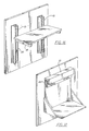
- Figure 16 illustrates a shelf supported on two brackets (as described with reference to Figure 3) mounted with their fins 20 engaged in shear by means of hook and loop material within two vertically mounted shear trap channels as shown in Figure 1.
- Figure 17 shows a variation of the support structure of Figure 16 in which the brackets are integrally formed with the shelf with fin portions 20 mounted by hook and loop material in shear to shear trap channels.
- Figure 18 illustrates a shelf supported by horizontal fin 20 within a horizontally disposed shear trap channel 10 such as is illustrated in Figure 2 the engagement again being by hook and loop material in shear.
- Figure 19 utilizes two shear trap channels of the type illustrated in Figure 2 but with the channels mounted vertically inwardly facing toward one another and with the fins 20 being on opposite ends of a mounting plate engaged within the channels by hook and loop material in shear and with the supported shelf originally attached to that plate.
- the component for example, the shelf may be progressively released from its shear engagement by means of hook and loop material by hinging a side 14 of the channel relative to the back 12.
- the present invention has met its objective by providing two entire families of components, including shelf brackets, that can be manufactured of economic and lightweight plastic, and the like, which provide for high stress and force resistant holding power while, at the same time, are easy to configure and reconfigure as the need dictates.
- a touch fastener as used in this application, comprises a first planar backing material part having a surface carrying hooks, mushrooms, balls on stems, pigtails, or the like, capable of engaging loops, hooks, mushrooms, balls on stems, pigtails, or the like, carried by a second planar backing material part to releasably fasten components together wherein the fastening strength in shear (i.e. against forces applied in the plane of the fastener) substantially exceeds the fastening strength resisting peeling separation of the fastener by the application of force normal to the plane thereof.
- hook and loop fastening systems and parts thereof shall be construed to include other types of touch fasteners in which the fastening strength in shear (i.e. against forces applied in the plane of the fastener) substantially exceeds the fastening strength resisting peeling separation of the fastener by the application of force normal to the plane thereof.
Landscapes
- Supports Or Holders For Household Use (AREA)
Applications Claiming Priority (2)
| Application Number | Priority Date | Filing Date | Title |
|---|---|---|---|
| US893388 | 1978-04-05 | ||
| US89338886A | 1986-08-05 | 1986-08-05 |
Publications (2)
| Publication Number | Publication Date |
|---|---|
| EP0256720A2 true EP0256720A2 (de) | 1988-02-24 |
| EP0256720A3 EP0256720A3 (de) | 1989-07-26 |
Family
ID=25401485
Family Applications (1)
| Application Number | Title | Priority Date | Filing Date |
|---|---|---|---|
| EP87306770A Withdrawn EP0256720A3 (de) | 1986-08-05 | 1987-07-30 | Einrichtung zum Aufhängen von Gegenständen an Wänden |
Country Status (1)
| Country | Link |
|---|---|
| EP (1) | EP0256720A3 (de) |
Family Cites Families (5)
| Publication number | Priority date | Publication date | Assignee | Title |
|---|---|---|---|---|
| DE1962000C3 (de) * | 1969-12-10 | 1973-10-18 | Messerschmitt-Boelkow-Blohm Gmbh, 8000 Muenchen | Einstuckige U formige Profilleiste |
| US3908830A (en) * | 1973-02-21 | 1975-09-30 | Harbor Ind Inc | Display device |
| US4271566A (en) * | 1976-12-13 | 1981-06-09 | Velcro Usa Inc. | Shear attachments using hook and loop fastener elements |
| GB1602264A (en) * | 1978-04-05 | 1981-11-11 | Green F W | Shelves |
| US4327837A (en) * | 1980-08-18 | 1982-05-04 | Ross Paul C | Hanging rack |
-
1987
- 1987-07-30 EP EP87306770A patent/EP0256720A3/de not_active Withdrawn
Also Published As
| Publication number | Publication date |
|---|---|
| EP0256720A3 (de) | 1989-07-26 |
Similar Documents
| Publication | Publication Date | Title |
|---|---|---|
| US4863127A (en) | Wall hanging system for articles | |
| US4887338A (en) | Shear trap hook and loop fastening system | |
| EP0256719A1 (de) | Vorrichtung mit Haken- und Schlaufenbefestigungsmaterial zum Aufräumen von Teilen | |
| US4879854A (en) | Hook and loop partitioning system | |
| US6651945B2 (en) | Device for hanging articles | |
| US7870983B2 (en) | Tissue box holder with magnetic and hook and loop attaching arrangements | |
| US6698124B2 (en) | Sign holder with hinge | |
| US5584455A (en) | Device for holding garment hangers | |
| US7261213B2 (en) | Closet partition system | |
| US20020153340A1 (en) | Net anchorage methods and apparatus | |
| US20090090828A1 (en) | Wall hanging system | |
| US6053468A (en) | Frame support system | |
| EP0527658A1 (de) | Regal | |
| US5477969A (en) | Wall panel display system | |
| US20060049124A1 (en) | Hanging structure | |
| US6561364B1 (en) | Portable shelf for mounting on a towel bar | |
| US9186001B2 (en) | Offset hanger for minimizing space between frame and wall | |
| US5346169A (en) | Support bracket | |
| US20070080265A1 (en) | Automatically self-locking utility clamp | |
| EP2063742B1 (de) | Wandmontierbares regalsystem mit rechteckigem rahmen und abnehmbaren tabletts | |
| EP0261774A1 (de) | Zum Aufhängen geeignete, miteinander verbindbare Behälter | |
| US5685516A (en) | Wall hanger | |
| US6471169B1 (en) | Multiple object support means for walls and method of use | |
| US6102461A (en) | Frame Handle | |
| WO2020102743A1 (en) | Wall and ceiling track systems for mounting devices |
Legal Events
| Date | Code | Title | Description |
|---|---|---|---|
| PUAI | Public reference made under article 153(3) epc to a published international application that has entered the european phase |
Free format text: ORIGINAL CODE: 0009012 |
|
| AK | Designated contracting states |
Kind code of ref document: A2 Designated state(s): AT BE CH DE ES FR GB IT LI LU NL SE |
|
| RAP1 | Party data changed (applicant data changed or rights of an application transferred) |
Owner name: VELCRO INDUSTRIES B.V. |
|
| PUAL | Search report despatched |
Free format text: ORIGINAL CODE: 0009013 |
|
| AK | Designated contracting states |
Kind code of ref document: A3 Designated state(s): AT BE CH DE ES FR GB IT LI LU NL SE |
|
| STAA | Information on the status of an ep patent application or granted ep patent |
Free format text: STATUS: THE APPLICATION IS DEEMED TO BE WITHDRAWN |
|
| 18D | Application deemed to be withdrawn |
Effective date: 19900201 |
|
| RIN1 | Information on inventor provided before grant (corrected) |
Inventor name: HANDLER, MICHAEL D. |