EP0256846A2 - Überwachung der Abgase eines Düsenflugzeugmotors - Google Patents
Überwachung der Abgase eines Düsenflugzeugmotors Download PDFInfo
- Publication number
- EP0256846A2 EP0256846A2 EP87307129A EP87307129A EP0256846A2 EP 0256846 A2 EP0256846 A2 EP 0256846A2 EP 87307129 A EP87307129 A EP 87307129A EP 87307129 A EP87307129 A EP 87307129A EP 0256846 A2 EP0256846 A2 EP 0256846A2
- Authority
- EP
- European Patent Office
- Prior art keywords
- sensor
- layer
- engine
- conducting
- electrically
- Prior art date
- Legal status (The legal status is an assumption and is not a legal conclusion. Google has not performed a legal analysis and makes no representation as to the accuracy of the status listed.)
- Withdrawn
Links
Images

Classifications
-
- G—PHYSICS
- G01—MEASURING; TESTING
- G01N—INVESTIGATING OR ANALYSING MATERIALS BY DETERMINING THEIR CHEMICAL OR PHYSICAL PROPERTIES
- G01N27/00—Investigating or analysing materials by the use of electric, electrochemical, or magnetic means
- G01N27/62—Investigating or analysing materials by the use of electric, electrochemical, or magnetic means by investigating the ionisation of gases, e.g. aerosols; by investigating electric discharges, e.g. emission of cathode
- G01N27/626—Investigating or analysing materials by the use of electric, electrochemical, or magnetic means by investigating the ionisation of gases, e.g. aerosols; by investigating electric discharges, e.g. emission of cathode using heat to ionise a gas
Definitions
- This invention relates to the condition monitoring of gas turbine engines and has particular reference to the construction of sensors for use in such condition monitoring.
- a sensor assembly for inclusion in the gas path of a gas turbine engine which sensor assembly comprises an electrically conducting surface having an electrically significant axial extent, mounting means for mounting said surface in a gas path of said engine, electrical insulating means serving to isolate said surface from the body of the engine and conducting means for connecting said surface to monitoring means external of the engine, the arrangement being such that in use the presence of electrically charged debris in the gas stream induces a charge on said conducting surface as debris passes for detection by said monitoring means.
- the sensor assembly may be an arcuate plate and the insulating means may be a layer of ceramic material provided on the surface thereof.
- the ceramic material of the arcuate plate may be juxtaposed the internal surface of the exhaust duct.
- the mounting means may comprise a stud connected with said surface and insulating means carrying said stud to locate the same, and to isolate the stud electrically from said surroundings.
- the electrode assembly may be inserted in the gas path of a gas turbine engine by applying an insulating layer to the internal surface of said exhaust duct and applying a metallic layer to the insulating surface.
- the mounting means in this case may be an adhesive if in a cool environment.
- each sensor may comprise an insulating layer, a bonding layer for bonding said insulating layer to a support surface and a conductive layer carried by said insulating layer, characterised that each of said layers is applied by spraying and in that connecting means provides for connecting said conductive layer with monitoring means externally of the engine assembly.
- the spraying may be errected by plasma spraying or by flame spraying.
- the bonding coat may have a thickness within the range or 0.5 to 1.5 mm, the ceramic layer may have a thickness of 0.5 to 1.6 mm and the conductive layer may have a thickness of 0.01 to 0.05 m.
- the bonding layer may comprise a nickel-chromium alloy containing 6% of aluminium.
- the ceramic layer may be selected from magnesium zirconate or a composition containing alumina, titanium dioxide, silica and iron oxide.
- the conductive layer may be selected from, a stainless steel containing by weight 17% chromium and 12% nickel together with to 3.5% of molybdemium and 1.5% silicon, or may be a nickel layer of 99%+ purity.
- Each sensor may be formed directly on the engine casing or in the alternative, may be formed on a support plate adapted to be secured to the engine casing.
- the engine casing is recessed to accommodate the sensor so that the sensor surface follows substantially the internal surface of the engine casing.
- Sensors in accordance with the present invention may be circumferentially spaced around ducting in the engine, or may be “spot” sensors which may be disposed in a staggered ring around an engine ducting or at other convenient places within the engine for sensing charged particles in the gas flow therein.
- the effect of length of the sensor in the direction of gas flow on the signal shape and duration has shown that the signal amplitude is related to sensor surface area and that charged debris sets up a charged field which is long compared to the change in axial length of the sensor and therefore, the change in signal duration is no discernable.
- the axial length of the sensor does not, therefore, appear to effect the frequency response of a sensor within a reasonable range of length, but in practical terms it is preferred that the minimum length of any sensor is constrained to approximately 10 mm usually by the problem of the lead out connectors.
- the maximum length is limited by the available space and by the capacitance consideration.
- the surface area should be maximised and the capacitance should be minimised. A compromise has to be achieved as capacitance is proportion to the surface area for the same dielectric material. In maximising the surface area, therefore, the capacitance could increase to an unacceptable level.
- a nominal value of 50 mm is a preferred maximum length for a sensor in accordance with the present invention. It will be appreciated, therefore, that the selection of different dielectric materials will enable improved sensor construction.
- the capacitance of each sensor should be below 2000 picofarads in order to be compatible with the input circuitry of exisiting electronics equipment capable of analysing the signals therefrom.
- the ceramic backing must be suitable for bonding to the sensing layer and the thermal expansion of the material of each layer should be matched as closely as possible to ensure that cracking and material loss does not occur in the relatively vigorous environment of the exhaust duct of a gas turbine engine.
- Thin coatings are more desirable since they are less likely to crack or to be lost from the surface, but they have low resistance and high capacitance compared with thicker coatings. Thicker coatings are more prone to cracking and material loss and coating thicknesses selected as set out above have been found to provide the ranges within which an acceptable compromise between the electrical properties on the one hand and the physical properties on the other are suitable for the particular compsitions selected.
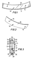
- a typical series of sensors as arranged in the gas duct of a jet engine is shown in Figure 4 and the individual sensors are shown in Figures 1 and 2.
- Each sensor comprises an arcuate plate 14 having a pair of arcuatly spaced holes 15.
- the face 16 or plate 14 is polished to provide a charge receiving surface and the periphery 17 and the back 18 are covered with a coating of ceramic electrically insulating material.
- Each plate 14 is secured to the engine casing 20 by means of a securing stud assembly 21.
- the securing stud assembly is shown in Figure 3 and comprises a generally cylindrical sleeve 22 which is provided on its internal surface towards a first end with an annulus 23. The external surface of the first end is threaded at 24 and the second end 25 of stud assembly 21 is provided with an annular recess (not shown).
- the second end is adapted to accommodate an insulating member 26 formed of a ceramic material and having a central bore adapted to accommodate a metal screw 27 adapted to be secured by nut 28 to ceramic member 26.
- Bolt 27 is provided with an enlarged slot 30 at its threaded end and is adapted to receive a flatten portion 31 of stud 32.
- stud 32 is generally cylindrical and is threaded at its first end 33 and is adapted to be engaged by nut 34 which serves to clamp a further ceramic block 35 between the shoulder 36 defined by constriction 23 against ceramic layer 26.
- the head 29 of bolt 27 serves to retain plate 16 in closely spaced relationship with the casing, but insulated therefrom whilst the bolt 27 and its associated stud serve to provide a means of electrical connection whereby the end 33 can be electrically connected to a conductor for connection to signal sensing and signal analytical equipment.
- sensors described above can be susbstituted by spray on sensors having parameters as set out in the following specific examples:-
- a bond coat composition was made up of a nickel-chromium alloy containing 6% of aluminium. This was sprayed by plasma spray techniques into a jet engine exhaust duct to form four circumferentially spaced arcuate bands on the internal surface of the exhaust duct. The thickness of the coating was 0.1 mm. The coating was allowed to cool and a further coating of a ceramic layer formed of magnesium zirconate containing 24% by weight of magnesium oxide was then sprayed on the bond coat in a thickness of 0.7mm.
- An conductive layer composition was prepared of a type 316 stainless steel having a composition of 17% chromium, 125 nickel, 2.5% molybdenium, 1% silicon, 0.1% carbon, the balance apart from incidental impurities being iron, was then plasma sprayed to a thickness of 0.025 mm onto the ceramic coating.
- An insulated stud connector was connected to the conductive layer and passed through the housing as described in copending application No. 8620239.
- Example 1 was repeated, the bond coat being as used in Example 1.
- the ceramic on this occasion was a composition comprising 94% by weight of alumina, 2.5% by weight of titanium dioxide, 2% silica and 1% of iron oxide.
- the ceramic material was plasma sprayed to a thickness of 1.05 mm onto the bond coat and the conductive layer of Example 1 was then applied thereover. Good results were again obtained comparable with the results of Example 1.
- Example 1 was repeated except that the conductive layer was substituted by a layer comprising 99.3% pure nickel, the balance being of incidental impurities.
- the conductive layer thickness is again 0.025 mm.
- Example 3 In service, the sensors of Example 3 provide a comparable result with the sensors of Examples 1 and 2.
- the coefficient of expansion between the bond coat, the ceramic layer and the conductive layer composition is sufficiently comparible that in the temperature range extent within the exhaust duct of the engine no significant cracking or spooling of the layers was noted.
- Examples 1 to 3 were repeated using flame spraying as opposed to plasma spraying of the sensor.
- the advantage of using flame spraying was to enable in situ application of the sensors to an exisiting engine without the need to remove the casing.
- the results obtained with the sensor was found to be substanially identical with the results in each of Examples 1 to 3 above.
Landscapes
- Chemical & Material Sciences (AREA)
- Chemical Kinetics & Catalysis (AREA)
- Electrochemistry (AREA)
- Physics & Mathematics (AREA)
- Health & Medical Sciences (AREA)
- Life Sciences & Earth Sciences (AREA)
- Analytical Chemistry (AREA)
- Biochemistry (AREA)
- General Health & Medical Sciences (AREA)
- General Physics & Mathematics (AREA)
- Immunology (AREA)
- Pathology (AREA)
- Testing Of Engines (AREA)
- Investigating Or Analyzing Materials By The Use Of Fluid Adsorption Or Reactions (AREA)
- Investigating Or Analyzing Materials By The Use Of Electric Means (AREA)
Applications Claiming Priority (4)
| Application Number | Priority Date | Filing Date | Title |
|---|---|---|---|
| GB8620239 | 1986-08-20 | ||
| GB868620239A GB8620239D0 (en) | 1986-08-20 | 1986-08-20 | Jet engine gas path conditioning monitoring |
| GB8702553 | 1987-02-05 | ||
| GB878702553A GB8702553D0 (en) | 1987-02-05 | 1987-02-05 | Jet engine gas path condition monitoring |
Publications (2)
| Publication Number | Publication Date |
|---|---|
| EP0256846A2 true EP0256846A2 (de) | 1988-02-24 |
| EP0256846A3 EP0256846A3 (de) | 1990-05-02 |
Family
ID=26291197
Family Applications (2)
| Application Number | Title | Priority Date | Filing Date |
|---|---|---|---|
| EP87307129A Withdrawn EP0256846A3 (de) | 1986-08-20 | 1987-08-12 | Überwachung der Abgase eines Düsenflugzeugmotors |
| EP19870307128 Withdrawn EP0256845A2 (de) | 1986-08-20 | 1987-08-12 | Überwachung der Abgase eines Düsenflugzeugmotors |
Family Applications After (1)
| Application Number | Title | Priority Date | Filing Date |
|---|---|---|---|
| EP19870307128 Withdrawn EP0256845A2 (de) | 1986-08-20 | 1987-08-12 | Überwachung der Abgase eines Düsenflugzeugmotors |
Country Status (1)
| Country | Link |
|---|---|
| EP (2) | EP0256846A3 (de) |
Cited By (3)
| Publication number | Priority date | Publication date | Assignee | Title |
|---|---|---|---|---|
| EP0284392A3 (en) * | 1987-03-25 | 1990-01-31 | Stewart Hughes Limited | Monitoring of foreign object ingestion in engines |
| EP0385569A3 (de) * | 1989-01-20 | 1990-09-12 | Stewart Hughes Ltd | Verfahren und Vorrichtung zur Feststellung von geladenen Teilchen in einer Gasströmung. |
| US10161785B2 (en) | 2014-04-24 | 2018-12-25 | Nuovo Pignone Srl | Method of monitoring rubbing between a rotary party and a stationary part in a rotating turbomachine, monitoring arrangement and turbomachine |
Families Citing this family (8)
| Publication number | Priority date | Publication date | Assignee | Title |
|---|---|---|---|---|
| GB2266772B (en) * | 1992-04-30 | 1995-10-25 | Pollution Control & Measuremen | Detecting particles in a gas flow |
| GB2272976B (en) * | 1992-11-30 | 1996-06-05 | Stewart Hughes Ltd | A sensor |
| GB2277154B (en) | 1993-04-06 | 1997-06-25 | Pollution Control & Measuremen | Method and apparatus for detecting particles in a flow |
| DE4311546A1 (de) * | 1993-04-07 | 1995-01-19 | Emmanuel Dr Rer Nat Bisse | Verwendung von kolloidalem Siliciumdioxid zur Behandlung der Sichelzellanämie, der Malaria sowie exogen induzierter Leukopenien |
| GB2336434A (en) * | 1998-04-17 | 1999-10-20 | Stewart Hughes Ltd | An apparatus for and method of monitoring a rotating machine |
| GB0410778D0 (en) | 2004-05-13 | 2004-06-16 | Rolls Royce Plc | Blade arrangement |
| US10900377B2 (en) | 2018-04-23 | 2021-01-26 | Honeywell International Inc. | System and method for monitoring for sand plugging in gas turbine engines |
| CN114659797B (zh) * | 2022-02-08 | 2025-08-01 | 南京航空航天大学 | 一种航空发动机气路故障模拟及静电监测试验平台 |
Family Cites Families (2)
| Publication number | Priority date | Publication date | Assignee | Title |
|---|---|---|---|---|
| US3775763A (en) * | 1972-03-07 | 1973-11-27 | Us Air Force | Apparatus for indicating the impending failure of a jet engine |
| US4584531A (en) * | 1982-10-04 | 1986-04-22 | United Technologies Corporation | Noncontact electrostatic hoop probe for combustion engines |
-
1987
- 1987-08-12 EP EP87307129A patent/EP0256846A3/de not_active Withdrawn
- 1987-08-12 EP EP19870307128 patent/EP0256845A2/de not_active Withdrawn
Cited By (3)
| Publication number | Priority date | Publication date | Assignee | Title |
|---|---|---|---|---|
| EP0284392A3 (en) * | 1987-03-25 | 1990-01-31 | Stewart Hughes Limited | Monitoring of foreign object ingestion in engines |
| EP0385569A3 (de) * | 1989-01-20 | 1990-09-12 | Stewart Hughes Ltd | Verfahren und Vorrichtung zur Feststellung von geladenen Teilchen in einer Gasströmung. |
| US10161785B2 (en) | 2014-04-24 | 2018-12-25 | Nuovo Pignone Srl | Method of monitoring rubbing between a rotary party and a stationary part in a rotating turbomachine, monitoring arrangement and turbomachine |
Also Published As
| Publication number | Publication date |
|---|---|
| EP0256846A3 (de) | 1990-05-02 |
| EP0256845A2 (de) | 1988-02-24 |
Similar Documents
| Publication | Publication Date | Title |
|---|---|---|
| EP0256846A2 (de) | Überwachung der Abgase eines Düsenflugzeugmotors | |
| US4645965A (en) | Cylinder pressure transmitter for an internal combustion engine | |
| CA2244886C (en) | Capacitive gap measurement device | |
| US4853582A (en) | Spark plug for use in internal combustion engine | |
| CN101421891A (zh) | 高容量火花塞的金属绝缘体涂层 | |
| US4570097A (en) | Electrical connections for a piezoelectric pressure transmitter for an internal combustion engine | |
| US4771209A (en) | Spark igniter having precious metal ground electrode inserts | |
| GB2285138A (en) | Temperature sensor | |
| JPH06133397A (ja) | 圧電センサ | |
| CA1238829A (en) | Glow plug having a conductive film heater | |
| JP2022074051A (ja) | 加速度変換器 | |
| JP4600778B2 (ja) | 目的物までの距離を静電的に測定する感知器 | |
| EP0179611B1 (de) | Zylinderdruckwandler für eine Verbrennungskraftmaschine | |
| EP0989369B1 (de) | Glühensensor- und - Motorteilkombination | |
| CA1168531A (en) | Spark igniter | |
| US8860291B2 (en) | Spark ignition device with in-built combustion sensor | |
| KR20020033163A (ko) | 압력 센서가 구비된 점화 플러그 및 그것이 장착된 열 기관 | |
| EP0511762B1 (de) | Piezoelektrischer Messfühler | |
| JP2012219748A (ja) | 点火システム | |
| US5886456A (en) | Ultrasonic transducer and ultrasonic detection and high temperature processing systems incorporating same | |
| EP1096140B2 (de) | Verbindungsstruktur für Glühkerze | |
| CA1317480C (en) | Input/output terminal assembly for flexure-type pressure transducers | |
| JP4024320B2 (ja) | スパークプラグ | |
| JPH0745353A (ja) | 圧力センサ内蔵プラグ | |
| EP0047660A1 (de) | Beschleunigungsmesser |
Legal Events
| Date | Code | Title | Description |
|---|---|---|---|
| PUAI | Public reference made under article 153(3) epc to a published international application that has entered the european phase |
Free format text: ORIGINAL CODE: 0009012 |
|
| AK | Designated contracting states |
Kind code of ref document: A2 Designated state(s): AT BE CH DE ES FR GB GR IT LI LU NL SE |
|
| PUAL | Search report despatched |
Free format text: ORIGINAL CODE: 0009013 |
|
| AK | Designated contracting states |
Kind code of ref document: A3 Designated state(s): AT BE CH DE ES FR GB GR IT LI LU NL SE |
|
| STAA | Information on the status of an ep patent application or granted ep patent |
Free format text: STATUS: THE APPLICATION IS DEEMED TO BE WITHDRAWN |
|
| 18D | Application deemed to be withdrawn |
Effective date: 19890901 |
|
| RIN1 | Information on inventor provided before grant (corrected) |
Inventor name: FORFITT, ROY Inventor name: FISHER, CELIA ELIZABETH |