EP0256862A1 - Teilchentransportsystem - Google Patents
Teilchentransportsystem Download PDFInfo
- Publication number
- EP0256862A1 EP0256862A1 EP19870307177 EP87307177A EP0256862A1 EP 0256862 A1 EP0256862 A1 EP 0256862A1 EP 19870307177 EP19870307177 EP 19870307177 EP 87307177 A EP87307177 A EP 87307177A EP 0256862 A1 EP0256862 A1 EP 0256862A1
- Authority
- EP
- European Patent Office
- Prior art keywords
- magnetic
- duct
- magnetic particles
- particles
- toner
- Prior art date
- Legal status (The legal status is an assumption and is not a legal conclusion. Google has not performed a legal analysis and makes no representation as to the accuracy of the status listed.)
- Withdrawn
Links
- 239000002245 particle Substances 0.000 title description 78
- 230000005291 magnetic effect Effects 0.000 claims abstract description 55
- 239000006249 magnetic particle Substances 0.000 claims abstract description 35
- BGPVFRJUHWVFKM-UHFFFAOYSA-N N1=C2C=CC=CC2=[N+]([O-])C1(CC1)CCC21N=C1C=CC=CC1=[N+]2[O-] Chemical compound N1=C2C=CC=CC2=[N+]([O-])C1(CC1)CCC21N=C1C=CC=CC1=[N+]2[O-] BGPVFRJUHWVFKM-UHFFFAOYSA-N 0.000 claims 1
- 230000032258 transport Effects 0.000 description 16
- 238000011161 development Methods 0.000 description 15
- 239000000463 material Substances 0.000 description 15
- 239000008187 granular material Substances 0.000 description 14
- 239000000843 powder Substances 0.000 description 11
- 238000004140 cleaning Methods 0.000 description 6
- 238000012546 transfer Methods 0.000 description 6
- 238000004891 communication Methods 0.000 description 3
- 230000005294 ferromagnetic effect Effects 0.000 description 3
- 238000000034 method Methods 0.000 description 3
- 239000000203 mixture Substances 0.000 description 3
- 239000000758 substrate Substances 0.000 description 3
- 239000011324 bead Substances 0.000 description 2
- 230000005484 gravity Effects 0.000 description 2
- 229910000838 Al alloy Inorganic materials 0.000 description 1
- 238000006424 Flood reaction Methods 0.000 description 1
- 229910001370 Se alloy Inorganic materials 0.000 description 1
- BUGBHKTXTAQXES-UHFFFAOYSA-N Selenium Chemical class [Se] BUGBHKTXTAQXES-UHFFFAOYSA-N 0.000 description 1
- XAGFODPZIPBFFR-UHFFFAOYSA-N aluminium Chemical compound [Al] XAGFODPZIPBFFR-UHFFFAOYSA-N 0.000 description 1
- 229910052782 aluminium Inorganic materials 0.000 description 1
- 230000005292 diamagnetic effect Effects 0.000 description 1
- 239000000428 dust Substances 0.000 description 1
- 238000003384 imaging method Methods 0.000 description 1
- 150000002500 ions Chemical class 0.000 description 1
- AJCDFVKYMIUXCR-UHFFFAOYSA-N oxobarium;oxo(oxoferriooxy)iron Chemical compound [Ba]=O.O=[Fe]O[Fe]=O.O=[Fe]O[Fe]=O.O=[Fe]O[Fe]=O.O=[Fe]O[Fe]=O.O=[Fe]O[Fe]=O.O=[Fe]O[Fe]=O AJCDFVKYMIUXCR-UHFFFAOYSA-N 0.000 description 1
- 230000005298 paramagnetic effect Effects 0.000 description 1
- 230000002093 peripheral effect Effects 0.000 description 1
- 108091008695 photoreceptors Proteins 0.000 description 1
- 238000012545 processing Methods 0.000 description 1
- 239000007921 spray Substances 0.000 description 1
- 238000003756 stirring Methods 0.000 description 1
Images
Classifications
-
- G—PHYSICS
- G03—PHOTOGRAPHY; CINEMATOGRAPHY; ANALOGOUS TECHNIQUES USING WAVES OTHER THAN OPTICAL WAVES; ELECTROGRAPHY; HOLOGRAPHY
- G03G—ELECTROGRAPHY; ELECTROPHOTOGRAPHY; MAGNETOGRAPHY
- G03G15/00—Apparatus for electrographic processes using a charge pattern
- G03G15/06—Apparatus for electrographic processes using a charge pattern for developing
- G03G15/08—Apparatus for electrographic processes using a charge pattern for developing using a solid developer, e.g. powder developer
- G03G15/0822—Arrangements for preparing, mixing, supplying or dispensing developer
Definitions
- This invention relates generally to an apparatus for transporting magnetic particles, and more particularly to an electrophotographic printing machine which uses such an apparatus in its development system.
- the apparatus includes a duct having magnetic particles therein; magnetic means for applying a magnetic force on the magnetic particles to hold the magnetic particles against at least a portion of the interior surface of said duct; and means for advancing at least the magnetic particles held against the interior surface of said duct along said duct.
- the process of electrophotographic printing includes charging a photoconductive member to a substantially uniform potential to sensitize the surface thereof.
- the charged portion of the photoconductive surface is exposed to a light image of an original document being reproduced.
- the latent image is developed by bringing a developer material into contact therewith. This forms a toner powder image on the photoconductive member which is subsequently transferred to a copy sheet.
- the powder image is heated to permanently affix it to the copy sheet in image configuration.
- a suitable developer material may comprise carrier granules having toner particles adhering triboelectrically thereto. This two component mixture is brought into contact with the electrostatic latent image recorded on the photoconductive surface. Toner particles are attracted from the carrier granules to the latent image. These toner particles adhere to the latent image to form a powder image on the photoconductive surface.
- a single component mixture comprising only toner particles may be brought into contact with the electrostatic latent image. In this latter case, the toner particles are once again deposited on the latent image to form a powder image thereon. In either case, additional toner particles must be furnished to the developer housing as the toner particles are depleted therefrom during the development process.
- One arrangement for furnishing additional toner particles is by periodically dumping a supply of toner particles from a sealed container into the toner hopper. This is accomplished by the machine operator when the electrophotographic printing machine indicates that the toner supply within the toner hopper is beneath a preselected level.
- Other techniques have employed remote toner containers housing a supply of toner particles which are subsequently advanced to the toner hopper by augers or bead chains. Generally, the remote toner container must be located above the toner hopper or very close to the same level thereof within the printing machine in order to insure that the auger of bead chain readily advances the toner particles from the remote supply to the toner hopper.
- US-A-3 983 841 a discloses a photoconductive drum having a plurality of spaced magnets mounted on one end thereof about the circumference. Tubes are arranged adjacent the upper and lower portion of the end of the photoconductive drum having the magnets disposed thereon. The tubes extend from a cleaning sump to the development sump. As the photoconductive drum rotates, toner particles are advanced from the cleaning sump to the development sump.
- US-A-4 101 211 describes a development apparatus containing a magnetic curtain seal adjacent an auger.
- the auger moves developer material between a sump and a development station.
- the magnetic curtain seal attracts a portion of the developer material to block a part of the passageway between the sump and the development station to prevent toner dust from escaping between the two compartments.
- US-A-4 142 655 discloses flexible augers for transporting toner particles from a remote container to a toner dispenser positioned adjacent the development system.
- US-A-4 170 287 describes magnetic augers in the form of a cylinder having magnetic helices in the surface thereof for transporting ferromagnetic particles, such as toner particles.
- Japanese Patent Application No. 54-30837 discloses a developing device in which repulsive magnetic fields are applied to a sleeve and screws.
- Japanese Patent Publication No. 58-209761 describes a a screw auger which stirs and mixes toner and a carrier in a magnet holder.
- the mixed carrier and toner is scattered and sticks to the surface of a sleeve by the magnetic field produced by a conveyance magnet.
- the developer is then carrier to the photoreceptor surface to develop the latent image recorded thereon.
- DE-1 054 013 discloses a vertical screw conveyor for ferromagnetic pieces comprising a helical tube rotating in a casing provided with magnets. The magnets are placed on the outside wall of the casing.
- the present invention is intended to provide an improved apparatus for transporting magnetic particles.
- the apparatus is characterised by said magnetic means being arcuately shaped and wrapped about at least a portion of the exterior surface of said duct and extending along the length thereof so that a plurality of magnetic poles contact the exterior surface of said duct along the length thereof.
- an electrophotographic printing machine of the type in which an electrostatic latent image is recorded on a photoconductive member.
- the printing machine includes means for developing the electrostatic latent image recorded on the photoconductive member.
- Means store a supply of magnetic particles therein.
- a duct is in communication with the storing means and the developing means.
- Means apply a magnetic force on the magnetic particles to hold the magnetic particles against at least a portion of the interior surface of the duct.
- Means advance at least the magnetic particles held against the interior surface of the duct along the duct from the storing means to the developing means.
- an electrophotographic printing machine of the type in which an electrostatic latent image is recorded on a photoconductive member.
- the printing machine includes means for developing the electrostatic latent image recorded on the photoconductive member.
- Means receive magnetic carrier granules.
- a duct is in communication with the receiving means and the developing means.
- Means apply a magnetic force on the magnetic particles to hold the magnetic particles against at least a portion of the interior surface of the duct.
- Means advance at least the magnetic particles held against the interior surface of the duct along the duct from the developing means to the receiving means.
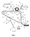
- FIG. 1 schematically depicts the various components of an illustrative electrophotographic printing machine incorporating the particle transport apparatus of the present invention therein. It will become evident from the following discussion that this apparatus is equally well suited for use in a wide variety of devices wherein magnetic particles are being transported and is not necessarily limited in its application to the particular embodiment depicted herein.
- the electrophotographic printing machine employs a belt 10 having a photoconductive surface deposited on a conductive substrate 14.
- photoconductive surface 12 is made from a selenium alloy with conductive substrate 14 being made from an aluminum alloy which is electrically grounded.
- Other suitable photoconductive surfaces and conductive substrates may also be employed.
- Belt 10 moves in the direction of arrow 16 to advance successive portions of photoconductive surface 12 through the various stations disposed about the path of movement thereof.
- belt 10 is entrained about stripping roller 18, tensioning roller 20 and drive roller 22.
- Drive roller 22 is mounted rotatably and in engagement with belt 10.
- Motor 24 rotates roller 22 to advance belt 10 in the direction of arrow 16.
- Roller 22 is coupled to motor 24 by suitable means, such as a drive belt.
- Stripper roller 18 and tension roller 20 are mounted freely rotatably.
- a corona generating device indicated generally by the reference numeral 26 charges a portion of photoconductive surface 12 of belt 10 to a relatively high, substantially uniform potential.
- the charged portion of photoconductive surface 12 is advanced through exposure station B.
- an original document 28 is positioned face down upon a transparent platen 30.
- Lamps 32 flash light rays onto original document 28.
- the light rays reflected from original document 28 are transmitted through lens 34 forming a light image thereof.
- Lens 34 focuses the light image onto the charged portion of photoconductive surface 12 to selectively dissipate the charge thereon.
- This records an electrostatic latent image on photoconductive surface 12 which corresponds to the informational areas contained within original document 28 disposed upon transparent platen 30.
- belt 10 advances the electrostatic latent image recorded on photoconductive surface 12 to development station C. While a light lens system has heretofore been described, one skilled in the art will appreciate that a modulated laser beam may also be employed to selectively discharge the charge on the photoconductive surface to record the electrostatic latent image thereon.
- a magnetic brush development system transports a developer mixture of carrier granules and toner particles into contact with the electrostatic latent image recorded on photoconductive surface 12.
- Magnetic brush development system 36 includes a magnetic brush developer roller 38.
- Magnetic brush developer roller 38 forms a brush of carrier granules and toner particles. The toner particles are attracted from the carrier granules to the electrostatic latent image forming a toner powder image on the photoconductive surface 12 of belt 10.
- a remote toner supply indicated generally by the reference numeral 40.
- Particle transport 42 connects developer unit 36 with remote toner supply 40 so as to advance the toner particles from remote toner supply 40 to developer unit 36.
- carrier granules may be added to or removed from the developer unit. In either event, the particles being transported along the duct must be magnetic.
- magnetic particles is intended to include ferromagnetic particles, paramagnetic particles and diamagnetic particles, as well as any other type of particles having any magnetic properties.
- sheet feeding apparatus 46 includes a feed roll 48 contacting the uppermost sheet of a stack of sheets 50. Feed roll 48 rotates to advance the uppermost sheet from stack 50 into chute 52. Chute 52 directs the advancing sheet of support material 44 into contact with photoconductive surface 12 of belt 10 in a timed sequence so that the toner powder image developed thereon contacts the advancing sheet of support material at transfer station D.
- Transfer station D includes a corona generating device 54 which sprays ions onto the back side of sheet 44. This attracts the toner powder image from photoconductive surface 12 to sheet 44. After transfer, the sheet continues to move in the direction of arrow 56 onto a conveyor (not shown) which advances the sheet to fusing station E.
- Fusing station E includes a fusing assembly, indicated generally by the reference numeral 58, which permanently affixes the transferred powdered image to sheet 40.
- fuser assembly 58 includes a heated fuser roller 60 and back-up roller 62.
- Sheet 44 passes between fuser roller 60 and back-up roller 62 with the toner powder image contacting fuser roller 60. In this way, the toner powder image is permanently affixed to sheet 44.
- chute 64 guides the advancing sheet to catch tray 66 for subsequent removal from the printing machine by the operator.
- Cleaning station F includes a pre-clean corona generating device (not shown) and a rotatably mounted fibrous brush 68 in contact with photoconductive surface 12.
- the pre-clean corona generating device neutralizes the charge attracting the particles to the photoconductive surface.
- These particles are cleaned from photoconductive surface 12 by the rotation of brush 68 in contact therewith.
- a discharge lamp (not shown) floods photoconductive surface 12 with light to dissipate any residual charge remaining thereon prior to the charging thereof for the next successive imaging cycle.
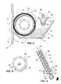
- developer unit 36 includes a developer roller 38 having non-magnetic tubular member 70 mounted rotatably therein.
- An elongated, cylindrical magnetic member 72 is mounted stationarily interiorly of tubular member 70 spaced from the interior peripheral surface thereof.
- Tubular member 70 rotates in the direction of arrow 74 so as to advance the developer material into contact with the electrostatic latent image recorded on photoconductive surface 12 of belt 10.
- developer material 80 disposed in chamber 76 of housing 78 is preferably composed of magnetic carrier granules having magnetic toner particles adhering triboelectrically thereto. It is thus evident that the electrostatic latent image attracts the toner particles from the carrier granules to develop the electrostatic latent image. Hence, toner particles are continually depleted from the developer material. If additional toner particles were not furnished to the developer material, the copies would eventually become progressively lighter degradating in quality.
- a toner particle dispenser furnishes additional toner particles to chamber 76 of housing 78.
- Toner particle dispenser 82 includes a hopper 84 storing a supply of toner particles in chamber 86 thereof.
- Hopper 84 is open ended with the open end being in communication with the entrance port of auger 88.
- Auger 88 includes a tubular member having a plurality of apertures therein and a helical member. As the helical member rotates, it advances the toner particles from hopper 86 along the tube thereof. The toner particles move along the tube and are dispensed through the apertures therein into chamber 80 of housing 78 so as to replenish the supply of toner particles therein.
- Additional toner particles are furnished to chamber 86 of toner dispenser 82 from remote toner supply 40 ( Figure 1) by particle transport 42.
- elongated magnetic member 72 is cylindrical and preferably made from barium ferrite having a plurality of magnetic poles impressed about the circumferential surface thereof.
- Tubular member 70 is made preferably from aluminum having the exterior circumferential surface thereof roughened.
- a particle transport of the type hereinafter described for furnishing additional toner particles may be employed to move carrier granules to the developer unit from a remotely located container or from the developer unit to a remotely located container.
- the detailed structure of particle transport 42 and remote toner supply 40 will be described hereinafter with reference to Figures 3 through 5, inclusive.
- remote toner supply 40 may be located any where in the printing machine having a convenient amount of space available. Alternatively, remote toner supply 40 may even be located external to the printing machine if it is desirable.
- Remote toner supply 40 includes a housing 90 defining a chamber 92 storing a supply of magnetic toner particles 94 therein.
- Particle transport 42 includes a duct 96 which is tubular, having an entrance region 98 disposed in chamber 92 so as to receive toner particles 94 thereat.
- An elongated shaft 100 is disposed interiorly of tubular member 96. Shaft 100 has a spirally wound protuberance 102 extending outwardly therefrom. Preferably, protuberance 102 is helically configured.
- Motor 104 is coupled to shaft 100.
- An elongated magnetic member 112 is positioned in contact with the exterior circumferential surface of tube 96.
- Elongated magnet 112 exerts a magnetic force on the magnetic toner particles in duct 96 to attract the magnetic toner particles to the interior surface 108 thereof.
- Actuation of motor 104 rotates shaft 100 which, in turn, causes rotation of protuberance 102 integral therewith.
- protuberance 102 rotates, the toner particles attracted to interior surface 108 of duct 96 are advanced from entrance port 98, along the longitudinal axis of tube 96, as indicated by arrow 110. In this way, a magnetic force is exerted substantially normal to the direction of movement of the toner particles.
- This magnetic force in conjunction with the force exerted on the particles by protuberance 102, permits the magnetic toner particles to move in the direction of arrow 110 even when this movement is opposed by the gravitational force exerted thereon.
- the magnetic toner particles move in the direction of arrow 110 until reaching the exit region of tube 96.
- the magnetic toner particles are discharged into hopper 84 of chamber 86 of toner dispenser 82. In this manner, magnetic toner particles are replenished in toner dispenser 82 from remote toner supply 40. Further details of particle transport 42 are shown in Figures 4 and 5.
- particle transport 42 includes an elongated tubular member 96 having an elongated arcuate permanent magnetic member 112 wrapped about a portion of the exterior circumferential surface thereof.
- elongated magnet 112 is wrapped about an angle of about 220° about tubular member 96.
- Elongated, arcuate magnet 112 extends, in a longitudinal direction from the entrance port to the exit port of tube 96. In this way, magnetic toner particles being transported along tube 96 are attracted to the interior surface 108 thereof. This enables the magnetic toner particles to be advanced against the gravitational force.
- Arcuate magnet 112 has a plurality of magnetic poles impressed about the surface thereof.
- magnet 112 may be a tube having tubular member 96 disposed interiorly thereof so that the magnetic forces extend about 360° thereover This produces magnetic forces in a direction substantially normal to the longitudinal access of tubular member 96. These magnetic forces attract the magnetic toner particles to the interior surface 108 of tubular member 96 insuring that these toner particles do not fall back to the entrance region of tubular member 96 under the influence of gravity, but, rather, advance along the longitudinal access of tubular member 96 due to the longitudinal forces exerted thereon by protuberance 102 of shaft 100.
- electromagnet may be employed instead of a permanent magnet.
- the particle transport may also be utilized to remove toner particles from the cleaning housing of an electrophotographic printing machine or to remove an excessive supply of toner particles or carrier granules from the developer housing.
- the particle transport of the present invention may be utilized in any system required to move magnetic particles.
- the particle transport of the present invention includes an elongated magnetic member extending from the entrance region to the exit region of a duct having an auger therein for moving magnetic particles therealong.
- the elongated magnet exerts a magnetic force on the magnetic particles to attract the magnetic particles to the interior surface of the duct. In this way, the magnetic particles do not slide, under the influence of gravity, back to the entrance region.
- the magnetic particles attracted to the interior surface of the duct are advanced by the auger from the entrance region to the exit region thereof.
Landscapes
- Physics & Mathematics (AREA)
- General Physics & Mathematics (AREA)
- Dry Development In Electrophotography (AREA)
- Magnetic Brush Developing In Electrophotography (AREA)
Applications Claiming Priority (2)
| Application Number | Priority Date | Filing Date | Title |
|---|---|---|---|
| US896353 | 1978-04-14 | ||
| US89635386A | 1986-08-14 | 1986-08-14 |
Publications (1)
| Publication Number | Publication Date |
|---|---|
| EP0256862A1 true EP0256862A1 (de) | 1988-02-24 |
Family
ID=25406062
Family Applications (1)
| Application Number | Title | Priority Date | Filing Date |
|---|---|---|---|
| EP19870307177 Withdrawn EP0256862A1 (de) | 1986-08-14 | 1987-08-14 | Teilchentransportsystem |
Country Status (2)
| Country | Link |
|---|---|
| EP (1) | EP0256862A1 (de) |
| JP (1) | JPS6348579A (de) |
Cited By (1)
| Publication number | Priority date | Publication date | Assignee | Title |
|---|---|---|---|---|
| NL9302145A (nl) * | 1993-12-09 | 1995-07-03 | Oce Nederland Bv | Transportinrichting voor ontwikkelpoeder. |
Families Citing this family (1)
| Publication number | Priority date | Publication date | Assignee | Title |
|---|---|---|---|---|
| JP4889008B2 (ja) * | 2005-09-07 | 2012-02-29 | 株式会社リコー | 現像剤搬送装置及び画像形成装置 |
Citations (4)
| Publication number | Priority date | Publication date | Assignee | Title |
|---|---|---|---|---|
| GB987985A (en) * | 1960-04-19 | 1965-03-31 | Rank Xerox Ltd | Stationary conveyor for magnetic materials |
| US4230069A (en) * | 1978-05-16 | 1980-10-28 | Compagnie Internationale Pour L'informatique Cii-Honeywell Bull | Particle feed arrangement for applying solid particles to the image carrier of a non-impact printer |
| US4234074A (en) * | 1978-06-30 | 1980-11-18 | James A. Herring | Apparatus for separating metal cuttings from liquid coolants |
| US4361396A (en) * | 1979-02-24 | 1982-11-30 | Konishiroku Photo Industry Co., Ltd. | Collecting apparatus for scattering toner |
-
1987
- 1987-08-07 JP JP62198008A patent/JPS6348579A/ja active Pending
- 1987-08-14 EP EP19870307177 patent/EP0256862A1/de not_active Withdrawn
Patent Citations (4)
| Publication number | Priority date | Publication date | Assignee | Title |
|---|---|---|---|---|
| GB987985A (en) * | 1960-04-19 | 1965-03-31 | Rank Xerox Ltd | Stationary conveyor for magnetic materials |
| US4230069A (en) * | 1978-05-16 | 1980-10-28 | Compagnie Internationale Pour L'informatique Cii-Honeywell Bull | Particle feed arrangement for applying solid particles to the image carrier of a non-impact printer |
| US4234074A (en) * | 1978-06-30 | 1980-11-18 | James A. Herring | Apparatus for separating metal cuttings from liquid coolants |
| US4361396A (en) * | 1979-02-24 | 1982-11-30 | Konishiroku Photo Industry Co., Ltd. | Collecting apparatus for scattering toner |
Cited By (3)
| Publication number | Priority date | Publication date | Assignee | Title |
|---|---|---|---|---|
| NL9302145A (nl) * | 1993-12-09 | 1995-07-03 | Oce Nederland Bv | Transportinrichting voor ontwikkelpoeder. |
| EP0662647A1 (de) * | 1993-12-09 | 1995-07-12 | Océ-Nederland B.V. | Transportvorrichtung für Pulverentwickler |
| US5638160A (en) * | 1993-12-09 | 1997-06-10 | Oce-Nederland, B.V. | Transport device for developer powder |
Also Published As
| Publication number | Publication date |
|---|---|
| JPS6348579A (ja) | 1988-03-01 |
Similar Documents
| Publication | Publication Date | Title |
|---|---|---|
| GB2110122A (en) | Dispensing toner particles | |
| EP0414455A2 (de) | Hybrid-Entwicklungssystem | |
| US4891673A (en) | Development system | |
| US5206693A (en) | Development unit having an asymmetrically biased electrode wires | |
| US3920329A (en) | Background removal apparatus | |
| US4682874A (en) | Particle level indicator | |
| US4926217A (en) | Particle transport | |
| US5128723A (en) | Scavengeless development system having toner deposited on a doner roller from a toner mover | |
| US5053824A (en) | Scavengeless development apparatus having a donor belt | |
| US4558659A (en) | Particle dispensing system | |
| US4080054A (en) | Device for replenishing toner particles | |
| US4724457A (en) | Developer unit using three angers in three chambers | |
| US4442789A (en) | Particle moving and dispensing system | |
| US4353637A (en) | Development system | |
| US5204719A (en) | Development system | |
| EP0256862A1 (de) | Teilchentransportsystem | |
| US4163614A (en) | Closed loop particle dispenser | |
| US5132735A (en) | Development apparatus with toner diverting members | |
| US5697018A (en) | Air handling system for a development housing | |
| US5315354A (en) | Carrier bead seal | |
| US4397546A (en) | Particle dispensing system | |
| CA1217044A (en) | Particle moving and dispensing system | |
| US4926790A (en) | Auger unit | |
| US5649271A (en) | Air handling system for a development housing | |
| US5359399A (en) | Hybrid scavengeless developer unit having a magnetic transport roller |
Legal Events
| Date | Code | Title | Description |
|---|---|---|---|
| PUAI | Public reference made under article 153(3) epc to a published international application that has entered the european phase |
Free format text: ORIGINAL CODE: 0009012 |
|
| AK | Designated contracting states |
Kind code of ref document: A1 Designated state(s): DE FR GB |
|
| 17P | Request for examination filed |
Effective date: 19880722 |
|
| 17Q | First examination report despatched |
Effective date: 19900613 |
|
| STAA | Information on the status of an ep patent application or granted ep patent |
Free format text: STATUS: THE APPLICATION HAS BEEN WITHDRAWN |
|
| 18W | Application withdrawn |
Withdrawal date: 19910114 |
|
| RIN1 | Information on inventor provided before grant (corrected) |
Inventor name: EDMUNDS, CYRIL Inventor name: CHART, STEVEN |