EP0256898A1 - Dispositif de vidange des silos - Google Patents
Dispositif de vidange des silos Download PDFInfo
- Publication number
- EP0256898A1 EP0256898A1 EP87401560A EP87401560A EP0256898A1 EP 0256898 A1 EP0256898 A1 EP 0256898A1 EP 87401560 A EP87401560 A EP 87401560A EP 87401560 A EP87401560 A EP 87401560A EP 0256898 A1 EP0256898 A1 EP 0256898A1
- Authority
- EP
- European Patent Office
- Prior art keywords
- gutter
- wall
- silo
- duct
- silos
- Prior art date
- Legal status (The legal status is an assumption and is not a legal conclusion. Google has not performed a legal analysis and makes no representation as to the accuracy of the status listed.)
- Granted
Links
- 239000000463 material Substances 0.000 description 3
- 240000008042 Zea mays Species 0.000 description 1
- 238000009434 installation Methods 0.000 description 1
- 238000003754 machining Methods 0.000 description 1
- 238000012423 maintenance Methods 0.000 description 1
- 230000014759 maintenance of location Effects 0.000 description 1
- 239000002184 metal Substances 0.000 description 1
Images
Classifications
-
- B—PERFORMING OPERATIONS; TRANSPORTING
- B65—CONVEYING; PACKING; STORING; HANDLING THIN OR FILAMENTARY MATERIAL
- B65G—TRANSPORT OR STORAGE DEVICES, e.g. CONVEYORS FOR LOADING OR TIPPING, SHOP CONVEYOR SYSTEMS OR PNEUMATIC TUBE CONVEYORS
- B65G65/00—Loading or unloading
- B65G65/30—Methods or devices for filling or emptying bunkers, hoppers, tanks, or like containers, of interest apart from their use in particular chemical or physical processes or their application in particular machines, e.g. not covered by a single other subclass
- B65G65/34—Emptying devices
- B65G65/36—Devices for emptying from the top
- B65G65/365—Devices for emptying from the top comprising a vertical passage located inside the container
-
- A—HUMAN NECESSITIES
- A01—AGRICULTURE; FORESTRY; ANIMAL HUSBANDRY; HUNTING; TRAPPING; FISHING
- A01F—PROCESSING OF HARVESTED PRODUCE; HAY OR STRAW PRESSES; DEVICES FOR STORING AGRICULTURAL OR HORTICULTURAL PRODUCE
- A01F25/00—Storing agricultural or horticultural produce; Hanging-up harvested fruit
- A01F25/16—Arrangements in forage silos
- A01F25/20—Unloading arrangements
Definitions
- the present invention relates to a device for emptying silos of the kind allowing laminar emptying while avoiding overpressures due to the shaking of the ensiled mass.
- the evacuation duct has been placed near one of the walls of the silo, but in doing so, an important drawback has been left which is the high cost of the installation.
- the evacuation duct is delimited by a metal tube which is very difficult to handle, to be fixed near a wall and on which it is difficult to make the openings.
- the present invention which overcomes these drawbacks, is recognizable in that the discharge duct is formed by the association of a part of the internal wall of the silo and a gutter, arranged vertically and held against said wall in leaving spaces between it and the edges of said gutter through which the ensiled product enters said duct.
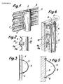
- the device is applied to a silo, the walls 1 of which are produced using corrugated sheets, the corrugations of which are arranged substantially horizontally.
- a gutter 2 arranged vertically and the internal wall of which houses with the portion of the wall of the silo disposed opposite, a conduit 3.
- the openings 4 allowing the ensiled product to enter the duct 3 are formed naturally by the edges 2a of the gutter and the internal hollows la of the corrugations of the wall 1.
- gutter 2 is a very simple member to produce and which poses neither storage nor transport problems.
- Figure 4 shows a second embodiment of the device applied to a silo with smooth walls such as those made of concrete.
- the gutter 6, similar to that 2, is held close to the internal face 7 of the silo by means of lugs 8 so as to delimit a discharge duct 9.
- the ensiled material enters the duct 9 through openings 10 delimited by the fields 8a of the legs 8, the face 7 and the edges 6a of the gutter.
Landscapes
- Life Sciences & Earth Sciences (AREA)
- Environmental Sciences (AREA)
- Engineering & Computer Science (AREA)
- Mechanical Engineering (AREA)
- Filling Or Emptying Of Bunkers, Hoppers, And Tanks (AREA)
Abstract
Description
- La présente invention est relative à un dispositif de vidange des silos du genre de ceux permettant la vidange laminaire en évitant les surpressions dues à l'ébranlement de la masse ensilée.
- Un tel dispositif est décrit,notamment, dans l'ouvrage "Silos" de Messieurs M.& A. REIMBERT, publié en 1956 chez Eyrolles.
- Il se compose essentiellement d'un conduit vertical d'évacuation situé au centre du silo,percé de trous sur toute sa hauteur et dont l'extrémité inférieure aboutit à l'orifice de vidange du silo. Le maintien de ce conduit est assuré par des bras le reliant aux parois du silo mais ces bras constituent des zones de rétention de la matière ensilée avec tous les inconvénients que cela présente.
- Pour limiter,notamment, les inconvénients ci-dessus, on a disposé le conduit d'évacuation à proximité de l'une des parois du silo, mais se faisant on a laissé subsisté un inconvénient important qui est le coût élevé de l'installation.
- En effet, le conduit d'évacuation est délimité par un tube métallique très difficile à manier, à fixer à proximité d'une paroi et sur lequel la réalisation des ouvertures est malaisée à effectuer.
- La présente invention, qui remédie à ces inconvénients, est ramarquable en ce que le conduit d'évacuation est formé par l'association d'une partie de la paroi interne du silo et d'une gouttière, disposée verticalement et maintenue contre ladite paroi en ménageant entre elle et les bords de ladite gouttière des espaces par lesquels le produit ensilé pénètre dans ledit conduit.
- L'invention sera mieux comprise par la description qui va suivre, faite en se référant au dessin annexé à titre d'exemple indicatif seulement, sur lequel :
- La figure 1 est une vue partielle, en perspective,montrant un premier mode de réalisation du dispositif de l'invention ;
- La figure 2 est une vue selon la flèche F de la figure 1;
- La figure 3 est une vue en coupe effectuée selon la ligne III-III de la figure 2;
- La figure 4 est une vue analogue à la figure 1 montrant un second mode de réalisation;
- La figure 5 est une vue analogue à celle 3 mais relative au second mode de réalisation.
- En se reportant à la figure 1, on voit que le dispositif est appliqué à un silo dont les parois 1 sont réalisées à l'aide de tôles ondulées dont les ondulations sont disposées sensiblement horizontalement.
- Selon l'invention, on fixe contre la paroi 1 une gouttière 2, disposée verticalement et dont la paroi interne ménage avec la portion de la paroi du silo disposée en regard, un conduit 3.
- Comme cela ressort tout particuliérement de la figure 2, les ouvertures 4 permettant au produit ensilé de pénétrer dans le conduit 3 sont formées naturellement par les bords 2a de la gouttière et les creux internes la des ondulations de la paroi 1.
- Comme une partie de la paroi usuelle du silo est utilisée pour former le conduit 3,il est évident qu'on réalise ainsi une économie de matière appréciable.
- A cela s'ajoute le fait que la gouttière 2 est un organe très simple à réaliser et qui ne pose ni de probléme de stockage ni de transport.
- Il faut signaler aussi qu'une économie substantielle est réalisée au niveau de l'usinage puisqu'il n'est plus nécessaire de découper des ouvertures dans la paroi du conduit.
- Des pattes 5,reliant la paroi du silo à la gouttière,permettent d'ajuster la section des ouvertures 4 tout en contribuant à une meilleure fixation de la gouttière.
- La figure 4 montre un second mode de réalisation du dispositif appliqué à un silo à parois lisses tel que ceux réalisés en béton.
- Dans ce cas, la gouttière 6,analogue à celle 2,est maintenue à proximité de la face interne 7 du silo par l'entremise de pattes 8 de façon à délimiter un conduit 9 d'évacuation.
- La matière ensilée pénètre dans le conduit 9 par des ouvertures 10 délimitées par les champs 8a des pattes 8, la face 7 et les bords 6a de la gouttière.
Claims (4)
Applications Claiming Priority (2)
| Application Number | Priority Date | Filing Date | Title |
|---|---|---|---|
| FR8609714 | 1986-07-04 | ||
| FR8609714A FR2600860B1 (fr) | 1986-07-04 | 1986-07-04 | Dispositif de vidange des silos. |
Publications (2)
| Publication Number | Publication Date |
|---|---|
| EP0256898A1 true EP0256898A1 (fr) | 1988-02-24 |
| EP0256898B1 EP0256898B1 (fr) | 1989-12-06 |
Family
ID=9337067
Family Applications (1)
| Application Number | Title | Priority Date | Filing Date |
|---|---|---|---|
| EP19870401560 Expired EP0256898B1 (fr) | 1986-07-04 | 1987-07-03 | Dispositif de vidange des silos |
Country Status (3)
| Country | Link |
|---|---|
| EP (1) | EP0256898B1 (fr) |
| DE (1) | DE3761085D1 (fr) |
| FR (1) | FR2600860B1 (fr) |
Families Citing this family (1)
| Publication number | Priority date | Publication date | Assignee | Title |
|---|---|---|---|---|
| FR2701462B1 (fr) * | 1993-02-12 | 1995-05-05 | Lagneau Jean Henri | Dispositif de vidange d'un silo comportant un conduit latéral d'évacuation. |
Citations (5)
| Publication number | Priority date | Publication date | Assignee | Title |
|---|---|---|---|---|
| FR1081986A (fr) * | 1953-05-18 | 1954-12-24 | Tangerois D Expansion Ind & Co | Perfectionnements apportés aux silos |
| FR1087925A (fr) * | 1954-09-03 | 1955-03-01 | Perfectionnement aux silos pour matières granuleuses ou pulvérulentes | |
| FR1423820A (fr) * | 1964-11-21 | 1966-01-07 | Procédé et dispositif de vidange des silos pour matières pulvérulentes ou granuleuses assurant le brassage des matières ensilées | |
| DE3020214A1 (de) * | 1980-05-28 | 1981-12-03 | Hermann 8831 Bergen Horndasch | Drainagevorrichtung fuer holzhochsilos |
| US4373623A (en) * | 1981-04-02 | 1983-02-15 | Bruecker George B | Silo discharge chute |
-
1986
- 1986-07-04 FR FR8609714A patent/FR2600860B1/fr not_active Expired - Fee Related
-
1987
- 1987-07-03 DE DE8787401560T patent/DE3761085D1/de not_active Expired - Lifetime
- 1987-07-03 EP EP19870401560 patent/EP0256898B1/fr not_active Expired
Patent Citations (5)
| Publication number | Priority date | Publication date | Assignee | Title |
|---|---|---|---|---|
| FR1081986A (fr) * | 1953-05-18 | 1954-12-24 | Tangerois D Expansion Ind & Co | Perfectionnements apportés aux silos |
| FR1087925A (fr) * | 1954-09-03 | 1955-03-01 | Perfectionnement aux silos pour matières granuleuses ou pulvérulentes | |
| FR1423820A (fr) * | 1964-11-21 | 1966-01-07 | Procédé et dispositif de vidange des silos pour matières pulvérulentes ou granuleuses assurant le brassage des matières ensilées | |
| DE3020214A1 (de) * | 1980-05-28 | 1981-12-03 | Hermann 8831 Bergen Horndasch | Drainagevorrichtung fuer holzhochsilos |
| US4373623A (en) * | 1981-04-02 | 1983-02-15 | Bruecker George B | Silo discharge chute |
Also Published As
| Publication number | Publication date |
|---|---|
| FR2600860A1 (fr) | 1988-01-08 |
| EP0256898B1 (fr) | 1989-12-06 |
| DE3761085D1 (de) | 1990-01-11 |
| FR2600860B1 (fr) | 1990-03-23 |
Similar Documents
| Publication | Publication Date | Title |
|---|---|---|
| FR2802977A1 (fr) | Dispositif constitue d'un filtre a air et d'un carburateur a membrane | |
| FR2731955A1 (fr) | Reservoir de carburant pour vehicules, en particulier vehicules automobiles | |
| EP0131480B1 (fr) | Dispositif diviseur de jet pour tête de remplissage | |
| EP0256898B1 (fr) | Dispositif de vidange des silos | |
| FR2561594A1 (fr) | Reservoir de liquide avec conduit d'event, notamment pour vehicule automobile | |
| EP0335452B1 (fr) | Machine à laver le linge possédant un trop plein | |
| FR2755576A1 (fr) | Poterie d'horticulture | |
| FR2695668A1 (fr) | Dispositif de trop-plein, notamment pour réservoir de chasse d'eau. | |
| FR2690955A1 (fr) | Système de siphon auto-amorçant adaptable à un conteneur liquide, et son application dans des installations d'épuration biologique. | |
| EP0240386A1 (fr) | Dispositif de vidange des silos | |
| FR2753340A1 (fr) | Dispositif pour contenir et suspendre une charge d'un materiau, par exemple pot de fleur | |
| FR2798819A1 (fr) | Support d'egouttage pour la fabrication de fromages | |
| EP1213235B1 (fr) | Dispositif de vidange de silo | |
| FR2722671A1 (fr) | Dispositif pour maintenir des fleurs dans un recipient en position sensiblement verticale et assurerleur bonne presentation sous forme de bouquet | |
| FR2460616A1 (fr) | Dispositif d'evacuation de l'eau de surface pour aquarium | |
| FR2641937A1 (fr) | Dispositif pour etiqueter des pots contenant des plants de vegetaux | |
| FR2699045A1 (fr) | Récipient pour plantes. | |
| FR2552121A1 (fr) | Filtre pour pompes de vidange de machines a laver | |
| CH604644A5 (en) | Paper filter for funnel of coffee maker | |
| CH316051A (fr) | Emballage, notamment pour produits liquides | |
| FR2501500A1 (fr) | Ecran anti-eclaboussures pour les trous d'aeration d'une chambre d'egouttement | |
| CH606645A5 (en) | Demountable by=pass plug for kitchen sink | |
| CH552176A (fr) | Cape de cheminee. | |
| FR3017633A1 (fr) | Dispositif de descente et d'evacuation d'eau pluviale en sortie d'une gouttiere de toit d'une construction | |
| FR2479849A1 (fr) | Appareil pour produire un biogaz |
Legal Events
| Date | Code | Title | Description |
|---|---|---|---|
| PUAI | Public reference made under article 153(3) epc to a published international application that has entered the european phase |
Free format text: ORIGINAL CODE: 0009012 |
|
| 17P | Request for examination filed |
Effective date: 19871221 |
|
| AK | Designated contracting states |
Kind code of ref document: A1 Designated state(s): BE CH DE ES GB IT LI NL SE |
|
| 17Q | First examination report despatched |
Effective date: 19890119 |
|
| GRAA | (expected) grant |
Free format text: ORIGINAL CODE: 0009210 |
|
| AK | Designated contracting states |
Kind code of ref document: B1 Designated state(s): BE CH DE ES GB IT LI NL SE |
|
| PG25 | Lapsed in a contracting state [announced via postgrant information from national office to epo] |
Ref country code: IT Free format text: LAPSE BECAUSE OF FAILURE TO SUBMIT A TRANSLATION OF THE DESCRIPTION OR TO PAY THE FEE WITHIN THE PRESCRIBED TIME-LIMIT;WARNING: LAPSES OF ITALIAN PATENTS WITH EFFECTIVE DATE BEFORE 2007 MAY HAVE OCCURRED AT ANY TIME BEFORE 2007. THE CORRECT EFFECTIVE DATE MAY BE DIFFERENT FROM THE ONE RECORDED. Effective date: 19891206 Ref country code: GB Effective date: 19891206 Ref country code: NL Effective date: 19891206 Ref country code: SE Effective date: 19891206 |
|
| REF | Corresponds to: |
Ref document number: 3761085 Country of ref document: DE Date of ref document: 19900111 |
|
| PG25 | Lapsed in a contracting state [announced via postgrant information from national office to epo] |
Ref country code: ES Free format text: LAPSE BECAUSE OF FAILURE TO SUBMIT A TRANSLATION OF THE DESCRIPTION OR TO PAY THE FEE WITHIN THE PRESCRIBED TIME-LIMIT Effective date: 19900317 |
|
| NLV1 | Nl: lapsed or annulled due to failure to fulfill the requirements of art. 29p and 29m of the patents act | ||
| GBV | Gb: ep patent (uk) treated as always having been void in accordance with gb section 77(7)/1977 [no translation filed] | ||
| PG25 | Lapsed in a contracting state [announced via postgrant information from national office to epo] |
Ref country code: CH Effective date: 19900731 Ref country code: LI Effective date: 19900731 |
|
| PLBE | No opposition filed within time limit |
Free format text: ORIGINAL CODE: 0009261 |
|
| STAA | Information on the status of an ep patent application or granted ep patent |
Free format text: STATUS: NO OPPOSITION FILED WITHIN TIME LIMIT |
|
| 26N | No opposition filed | ||
| REG | Reference to a national code |
Ref country code: CH Ref legal event code: PL |
|
| PGFP | Annual fee paid to national office [announced via postgrant information from national office to epo] |
Ref country code: BE Payment date: 19940729 Year of fee payment: 8 |
|
| PGFP | Annual fee paid to national office [announced via postgrant information from national office to epo] |
Ref country code: DE Payment date: 19940930 Year of fee payment: 8 |
|
| PG25 | Lapsed in a contracting state [announced via postgrant information from national office to epo] |
Ref country code: BE Effective date: 19950731 |
|
| BERE | Be: lapsed |
Owner name: DROUET JEAN-FRANCOIS ADRIEN LOUIS Effective date: 19950731 |
|
| PG25 | Lapsed in a contracting state [announced via postgrant information from national office to epo] |
Ref country code: DE Effective date: 19960402 |