EP0256974A2 - Machine à cintrer pour acier à béton - Google Patents
Machine à cintrer pour acier à béton Download PDFInfo
- Publication number
- EP0256974A2 EP0256974A2 EP87810205A EP87810205A EP0256974A2 EP 0256974 A2 EP0256974 A2 EP 0256974A2 EP 87810205 A EP87810205 A EP 87810205A EP 87810205 A EP87810205 A EP 87810205A EP 0256974 A2 EP0256974 A2 EP 0256974A2
- Authority
- EP
- European Patent Office
- Prior art keywords
- bolt
- shaped piece
- shaft
- support
- bending
- Prior art date
- Legal status (The legal status is an assumption and is not a legal conclusion. Google has not performed a legal analysis and makes no representation as to the accuracy of the status listed.)
- Granted
Links
Images

Classifications
-
- B—PERFORMING OPERATIONS; TRANSPORTING
- B21—MECHANICAL METAL-WORKING WITHOUT ESSENTIALLY REMOVING MATERIAL; PUNCHING METAL
- B21D—WORKING OR PROCESSING OF SHEET METAL OR METAL TUBES, RODS OR PROFILES WITHOUT ESSENTIALLY REMOVING MATERIAL; PUNCHING METAL
- B21D11/00—Bending not restricted to forms of material mentioned in only one of groups B21D5/00, B21D7/00, B21D9/00; Bending not provided for in groups B21D5/00 - B21D9/00; Twisting
- B21D11/10—Bending specially adapted to produce specific articles, e.g. leaf springs
- B21D11/12—Bending specially adapted to produce specific articles, e.g. leaf springs the articles being reinforcements for concrete
-
- B—PERFORMING OPERATIONS; TRANSPORTING
- B21—MECHANICAL METAL-WORKING WITHOUT ESSENTIALLY REMOVING MATERIAL; PUNCHING METAL
- B21D—WORKING OR PROCESSING OF SHEET METAL OR METAL TUBES, RODS OR PROFILES WITHOUT ESSENTIALLY REMOVING MATERIAL; PUNCHING METAL
- B21D7/00—Bending rods, profiles, or tubes
- B21D7/06—Bending rods, profiles, or tubes in press brakes or between rams and anvils or abutments; Pliers with forming dies
- B21D7/063—Pliers with forming dies
Definitions
- Such a device for bending partially concreted, or fastened, individual reinforcing steels by approximately 90 degrees which is characterized in that two shaped pieces (1,6) are pivotally connected to one another via a bolt (15) serving as a pivot and bending axis, the one shaped piece (1) being adjustable in height a support (3) is guided and lockable and has a holder (17) open on one side for receiving the reinforcing steel (16) to be bent, the free space of which tangentially adjoins the bolt (15) that on the other fitting (6) there is a freely rotatable shaft (18) is arranged parallel to the bolt (15), further that on this fitting (6) a lever (7) is attached, which is intended to act as a power arm, while the distance between the pivot axis and shaft (18) as It is determined to act with a low load, and that the two molded parts (1, 6) can be swung apart so far that the shaft (18) completely traverses the extension of the free space formed by the holder (17).
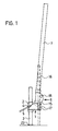
- the bending device essentially consists of the shaped piece 1, which is welded firmly to a square tube section 2, which is placed over a square tube 3 that fits into it and serves as a support 3.
- the fitting 1 is thereby guided along the support 3 so as to be vertically displaceable.
- the support 3 has a longitudinal slot through which a clamping screw 4 passes, which is held in a thread in the pipe section 2.
- the screw 4 is provided with a lever handle 5, by means of which the screw 4 can be tightened, pressing on the opposite inner wall of the support and thereby clamping the pipe section 2 with the support 3.
- the fitting 1 can therefore be locked at any height.
- the second fitting 6 is pivotally connected to the fitting 1.
- a lever 7 is fastened, which in the pivoted-out position of the fitting 6 is roughly normal height of a worker ends. It acts as a power arm when bending by the worker swiveling it towards itself.
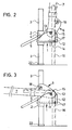
- FIG 2 the moldings 1 and 6 are shown on an enlarged scale. The illustration shows them in the swung-out position from the side.
- the fitting 1 is box-shaped with the walls 11, 12 and 13, and the bottom 14. Between the walls 11 and 13, a bolt 15 is arranged, around which the reinforcing steel 16, which is shown in broken lines, is bent. The bolt 15 also serves as a pivot axis 15 and therefore passes through the fitting 6.
- the thickness of the shaped piece 6 is dimensioned approximately half as large as the distance between the walls 11 and 13 of the shaped piece 1. So that the shaped piece 6 always bears against the wall 13, a shoulder on which the shaped piece 6 is in contact can be turned on the bolt 15 .
- the bottom 14 and the wall 11 of the molded part 1 have recesses through which a holder 17 is formed, which encloses a free space which is intended to accommodate the reinforcing steel to be bent, as is indicated by the steel drawn in broken lines.
- the shaped piece 6 pivotably articulated on the pin 15 has at some distance from the bolt 15 on a freely rotatable shaft 18 which runs parallel to the bolt 15.
- This shaft 18 is advantageously ball-bearing.
- the bolt 15 and the shaft 18 lie in such a way that the reinforcing steel to be bent can be inserted between them.
- FIG. 3 now shows the two molded parts 1 and 6 in the swiveled-in position after the bending of the reinforcing steel, again drawn in broken lines, has taken place.
- the shaft 18 rolls on the outer side of the bend of the steel, while on the inner side of the bend the steel is bent tightly around the bolt 15. Due to the rotatability of the shaft 18, the bending force is considerably reduced.
- Figure 4 shows the two molded parts 1 and 6 from behind.
- the bolt 15 is secured to the wall 13 of the fitting 1 by means of a snap ring 19.
- the shaft 18 is fastened to the shaped piece 6 with a simple hexagon nut 20.
- the slot 21 can be seen through which the clamping screw 4 is guided.
- the lever handle 5 allows this screw 4 to be tightened effortlessly in order to lock the shaped piece 1 at any height on the support 3.
- the device is now used as follows:
- the desired distance from the exit of the steel to be bent to the bending point is set by means of the height adjustment of the molding 1. With the screw 4 this setting is locked by a handle on the handle lever 5. Now you take the device on the lever 7 and guide it to the reinforcing steel to be bent so that it comes to rest in the space formed by the holder 17. The support 3 now lies with its foot 22 vertically on the concrete base. Now you pull the lever 7 against you, whereby the lever 7 and the fitting 6 are pivoted about the pin 15.
- the shaft 18 presses on the steel 16, which abuts on the bolt 15 on its other side.
- the distance between the bolt 15 and the support point of the shaft 18 acts as a load arm.
- the steel 16 is bent tightly around the bolt 15, while the shaft 18 rolls on the outer side of the bend of the steel 16.
- the device is simply lifted away to the side, the lever 7 is pivoted back and the device is attached to the next steel.
Landscapes
- Engineering & Computer Science (AREA)
- Mechanical Engineering (AREA)
- Bending Of Plates, Rods, And Pipes (AREA)
- Bridges Or Land Bridges (AREA)
- Forms Removed On Construction Sites Or Auxiliary Members Thereof (AREA)
- Heat Treatment Of Steel (AREA)
- Rod-Shaped Construction Members (AREA)
- Reinforcement Elements For Buildings (AREA)
Priority Applications (1)
| Application Number | Priority Date | Filing Date | Title |
|---|---|---|---|
| AT87810205T ATE84453T1 (de) | 1986-08-14 | 1987-04-03 | Geraet zum biegen von armierungsstahl. |
Applications Claiming Priority (2)
| Application Number | Priority Date | Filing Date | Title |
|---|---|---|---|
| CH3267/86 | 1986-08-14 | ||
| CH3267/86A CH670583A5 (fr) | 1986-08-14 | 1986-08-14 |
Publications (3)
| Publication Number | Publication Date |
|---|---|
| EP0256974A2 true EP0256974A2 (fr) | 1988-02-24 |
| EP0256974A3 EP0256974A3 (en) | 1990-01-31 |
| EP0256974B1 EP0256974B1 (fr) | 1993-01-13 |
Family
ID=4252281
Family Applications (1)
| Application Number | Title | Priority Date | Filing Date |
|---|---|---|---|
| EP87810205A Expired - Lifetime EP0256974B1 (fr) | 1986-08-14 | 1987-04-03 | Machine à cintrer pour acier à béton |
Country Status (5)
| Country | Link |
|---|---|
| EP (1) | EP0256974B1 (fr) |
| AT (1) | ATE84453T1 (fr) |
| CH (1) | CH670583A5 (fr) |
| DE (2) | DE3783537D1 (fr) |
| ES (1) | ES2038206T3 (fr) |
Cited By (4)
| Publication number | Priority date | Publication date | Assignee | Title |
|---|---|---|---|---|
| EP0844917A4 (fr) * | 1995-05-18 | 1998-07-08 | ||
| RU2267399C1 (ru) * | 2004-05-11 | 2006-01-10 | Сергей Михайлович Анпилов | Устройство для резки и гибки арматуры |
| AU2013101432B4 (en) * | 2013-10-31 | 2016-02-04 | Creative Living Queensland Pty Ltd | A Portable Bending Tool |
| US20160167104A1 (en) * | 2008-05-05 | 2016-06-16 | Edgewell Personal Care Brands Llc | Method of making a bent razor blade |
Family Cites Families (6)
| Publication number | Priority date | Publication date | Assignee | Title |
|---|---|---|---|---|
| US2675723A (en) * | 1954-04-20 | Pivoted rod bending hand tool | ||
| FR1505858A (fr) * | 1966-12-20 | 1967-12-15 | Appareil pour cintrer simultanément plusieurs éléments métalliques tels que tubes, fers à béton, profilés ou autres | |
| US3732721A (en) * | 1971-06-23 | 1973-05-15 | Cusimano Tool Dev Corp | Portable apparatus for forming bends in concrete reinforcing rods |
| SE8104572L (sv) * | 1981-07-28 | 1983-01-29 | Englund Thomas U Y | Uppberningsanordning |
| FR2549399B1 (fr) * | 1983-07-19 | 1985-11-29 | Mure Ets | Outil pour le redressement ou la mise en forme de profiles, notamment d'armatures, encastres a une extremite |
| DE8428220U1 (de) * | 1984-09-26 | 1984-11-29 | Meyer, Walter, 2000 Hamburg | Überbinderzange |
-
1986
- 1986-08-14 CH CH3267/86A patent/CH670583A5/de not_active IP Right Cessation
-
1987
- 1987-04-03 DE DE8787810205T patent/DE3783537D1/de not_active Expired - Fee Related
- 1987-04-03 AT AT87810205T patent/ATE84453T1/de not_active IP Right Cessation
- 1987-04-03 ES ES198787810205T patent/ES2038206T3/es not_active Expired - Lifetime
- 1987-04-03 EP EP87810205A patent/EP0256974B1/fr not_active Expired - Lifetime
- 1987-06-27 DE DE8708915U patent/DE8708915U1/de not_active Expired
Cited By (5)
| Publication number | Priority date | Publication date | Assignee | Title |
|---|---|---|---|---|
| EP0844917A4 (fr) * | 1995-05-18 | 1998-07-08 | ||
| RU2267399C1 (ru) * | 2004-05-11 | 2006-01-10 | Сергей Михайлович Анпилов | Устройство для резки и гибки арматуры |
| US20160167104A1 (en) * | 2008-05-05 | 2016-06-16 | Edgewell Personal Care Brands Llc | Method of making a bent razor blade |
| US10413962B2 (en) | 2008-05-05 | 2019-09-17 | Edgewell Personal Care Brands, Llc | Method of making a bent razor blade |
| AU2013101432B4 (en) * | 2013-10-31 | 2016-02-04 | Creative Living Queensland Pty Ltd | A Portable Bending Tool |
Also Published As
| Publication number | Publication date |
|---|---|
| EP0256974A3 (en) | 1990-01-31 |
| DE3783537D1 (de) | 1993-02-25 |
| CH670583A5 (fr) | 1989-06-30 |
| EP0256974B1 (fr) | 1993-01-13 |
| ES2038206T3 (es) | 1993-07-16 |
| DE8708915U1 (de) | 1987-09-17 |
| ATE84453T1 (de) | 1993-01-15 |
Similar Documents
| Publication | Publication Date | Title |
|---|---|---|
| EP0256974B1 (fr) | Machine à cintrer pour acier à béton | |
| DE29919365U1 (de) | Christbaumständer (Seilzug III) | |
| DE1291952B (de) | Einrichtung zum Befestigen von Regenabflussrohren an Bauwerkswaenden | |
| DE10018658B4 (de) | Rundschalungsmodul | |
| EP0196489B1 (fr) | Dispositif pour emboîter deux tuyaux | |
| DE19718937A1 (de) | Herstellung von zumindest einer Biegung | |
| WO2003004793A2 (fr) | Structure d'ancrage pour toit | |
| DE19612789C1 (de) | Vorrichtung zum Festlegen von Rohrleitungen | |
| EP0653530A1 (fr) | Support de garde-corps pour toitures | |
| DE143991C (fr) | ||
| DE572588C (de) | Vorrichtung zum Biegen von Rohren mittels Formstuecks | |
| DE3030933C2 (de) | Flächenheizung | |
| CH471298A (de) | Kantholzträger, insbesondere für Längsverbinder an Schalträgern | |
| DE202024103955U1 (de) | Schneidgerät für Dämmplatten mit Fixierbügel zum klemmenden Fixieren | |
| DE443717C (de) | Biegevorrichtung fuer Eisenstaebe, insbesondere solche fuer den Einbau in Eisenbetondecken | |
| DE1434390C (de) | Schalung zum Herstellen von Stahlbetonnppendecken | |
| EP0434603B1 (fr) | Dispositif pour la fixation de la distance entre deux parois de coffrage opposées | |
| DE7601264U1 (de) | Vorrichtung zum Schneiden von Profilleisten auf Gehrung oder anders geformter Ausschnitte | |
| EP1832695A2 (fr) | Connection d'échafaudage | |
| DE2637846A1 (de) | An einem traggeruest befestigbare wandverkleidung | |
| DE2840644C2 (de) | Biegevorrichtung für dünnwandige Rohre | |
| CH653429A5 (en) | Radiant heating system | |
| DE3013849A1 (de) | Biegedornanordnung fuer eine biegemaschine zum gleichzeitigen biegen von betonstahldraehten | |
| DE9419647U1 (de) | Biege- und Abkantzange für Flacheisen | |
| AT1842U1 (de) | Vorrichtung zum schutz vor aus mauern ragenden bewehrungseisen |
Legal Events
| Date | Code | Title | Description |
|---|---|---|---|
| PUAI | Public reference made under article 153(3) epc to a published international application that has entered the european phase |
Free format text: ORIGINAL CODE: 0009012 |
|
| AK | Designated contracting states |
Kind code of ref document: A2 Designated state(s): AT BE CH DE ES FR GB GR IT LI LU NL SE |
|
| PUAL | Search report despatched |
Free format text: ORIGINAL CODE: 0009013 |
|
| AK | Designated contracting states |
Kind code of ref document: A3 Designated state(s): AT BE CH DE ES FR GB GR IT LI LU NL SE |
|
| 17P | Request for examination filed |
Effective date: 19900314 |
|
| 17Q | First examination report despatched |
Effective date: 19910819 |
|
| RAP1 | Party data changed (applicant data changed or rights of an application transferred) |
Owner name: EGCO AG |
|
| GRAA | (expected) grant |
Free format text: ORIGINAL CODE: 0009210 |
|
| AK | Designated contracting states |
Kind code of ref document: B1 Designated state(s): AT BE CH DE ES FR GB GR IT LI LU NL SE |
|
| PG25 | Lapsed in a contracting state [announced via postgrant information from national office to epo] |
Ref country code: SE Effective date: 19930113 Ref country code: GR Free format text: LAPSE BECAUSE OF FAILURE TO SUBMIT A TRANSLATION OF THE DESCRIPTION OR TO PAY THE FEE WITHIN THE PRESCRIBED TIME-LIMIT Effective date: 19930113 |
|
| REF | Corresponds to: |
Ref document number: 84453 Country of ref document: AT Date of ref document: 19930115 Kind code of ref document: T |
|
| REF | Corresponds to: |
Ref document number: 3783537 Country of ref document: DE Date of ref document: 19930225 |
|
| ITF | It: translation for a ep patent filed | ||
| ET | Fr: translation filed | ||
| PG25 | Lapsed in a contracting state [announced via postgrant information from national office to epo] |
Ref country code: LU Free format text: LAPSE BECAUSE OF NON-PAYMENT OF DUE FEES Effective date: 19930430 |
|
| GBT | Gb: translation of ep patent filed (gb section 77(6)(a)/1977) |
Effective date: 19930408 |
|
| REG | Reference to a national code |
Ref country code: ES Ref legal event code: FG2A Ref document number: 2038206 Country of ref document: ES Kind code of ref document: T3 |
|
| PLBE | No opposition filed within time limit |
Free format text: ORIGINAL CODE: 0009261 |
|
| STAA | Information on the status of an ep patent application or granted ep patent |
Free format text: STATUS: NO OPPOSITION FILED WITHIN TIME LIMIT |
|
| 26N | No opposition filed | ||
| PGFP | Annual fee paid to national office [announced via postgrant information from national office to epo] |
Ref country code: GB Payment date: 19940323 Year of fee payment: 8 |
|
| PGFP | Annual fee paid to national office [announced via postgrant information from national office to epo] |
Ref country code: BE Payment date: 19940407 Year of fee payment: 8 |
|
| PGFP | Annual fee paid to national office [announced via postgrant information from national office to epo] |
Ref country code: FR Payment date: 19940426 Year of fee payment: 8 |
|
| PGFP | Annual fee paid to national office [announced via postgrant information from national office to epo] |
Ref country code: ES Payment date: 19940429 Year of fee payment: 8 Ref country code: AT Payment date: 19940429 Year of fee payment: 8 |
|
| PGFP | Annual fee paid to national office [announced via postgrant information from national office to epo] |
Ref country code: NL Payment date: 19940430 Year of fee payment: 8 |
|
| PG25 | Lapsed in a contracting state [announced via postgrant information from national office to epo] |
Ref country code: GB Effective date: 19950403 Ref country code: AT Effective date: 19950403 |
|
| PG25 | Lapsed in a contracting state [announced via postgrant information from national office to epo] |
Ref country code: ES Free format text: LAPSE BECAUSE OF NON-PAYMENT OF DUE FEES Effective date: 19950404 |
|
| PG25 | Lapsed in a contracting state [announced via postgrant information from national office to epo] |
Ref country code: BE Effective date: 19950430 |
|
| BERE | Be: lapsed |
Owner name: EGCO A.G. Effective date: 19950430 |
|
| PG25 | Lapsed in a contracting state [announced via postgrant information from national office to epo] |
Ref country code: NL Effective date: 19951101 |
|
| GBPC | Gb: european patent ceased through non-payment of renewal fee |
Effective date: 19950403 |
|
| PG25 | Lapsed in a contracting state [announced via postgrant information from national office to epo] |
Ref country code: FR Effective date: 19951229 |
|
| NLV4 | Nl: lapsed or anulled due to non-payment of the annual fee |
Effective date: 19951101 |
|
| REG | Reference to a national code |
Ref country code: FR Ref legal event code: ST |
|
| REG | Reference to a national code |
Ref country code: ES Ref legal event code: FD2A Effective date: 19990201 |
|
| PGFP | Annual fee paid to national office [announced via postgrant information from national office to epo] |
Ref country code: DE Payment date: 20020418 Year of fee payment: 16 |
|
| PGFP | Annual fee paid to national office [announced via postgrant information from national office to epo] |
Ref country code: CH Payment date: 20030728 Year of fee payment: 17 |
|
| PG25 | Lapsed in a contracting state [announced via postgrant information from national office to epo] |
Ref country code: DE Free format text: LAPSE BECAUSE OF NON-PAYMENT OF DUE FEES Effective date: 20031101 |
|
| PG25 | Lapsed in a contracting state [announced via postgrant information from national office to epo] |
Ref country code: LI Free format text: LAPSE BECAUSE OF NON-PAYMENT OF DUE FEES Effective date: 20040430 Ref country code: CH Free format text: LAPSE BECAUSE OF NON-PAYMENT OF DUE FEES Effective date: 20040430 |
|
| REG | Reference to a national code |
Ref country code: CH Ref legal event code: PL |
|
| PG25 | Lapsed in a contracting state [announced via postgrant information from national office to epo] |
Ref country code: IT Free format text: LAPSE BECAUSE OF NON-PAYMENT OF DUE FEES;WARNING: LAPSES OF ITALIAN PATENTS WITH EFFECTIVE DATE BEFORE 2007 MAY HAVE OCCURRED AT ANY TIME BEFORE 2007. THE CORRECT EFFECTIVE DATE MAY BE DIFFERENT FROM THE ONE RECORDED. Effective date: 20050403 |