EP0257116A1 - Appareil et méthode d'ajustement du rythme du coeur ou de stimulateur en fonction du temps d'éjection en vue d'obtenir le fonctionnement cardiaque - Google Patents
Appareil et méthode d'ajustement du rythme du coeur ou de stimulateur en fonction du temps d'éjection en vue d'obtenir le fonctionnement cardiaque Download PDFInfo
- Publication number
- EP0257116A1 EP0257116A1 EP86111600A EP86111600A EP0257116A1 EP 0257116 A1 EP0257116 A1 EP 0257116A1 EP 86111600 A EP86111600 A EP 86111600A EP 86111600 A EP86111600 A EP 86111600A EP 0257116 A1 EP0257116 A1 EP 0257116A1
- Authority
- EP
- European Patent Office
- Prior art keywords
- rate
- pacer
- ejection time
- heart
- changes
- Prior art date
- Legal status (The legal status is an assumption and is not a legal conclusion. Google has not performed a legal analysis and makes no representation as to the accuracy of the status listed.)
- Granted
Links
Images


Classifications
-
- A—HUMAN NECESSITIES
- A61—MEDICAL OR VETERINARY SCIENCE; HYGIENE
- A61N—ELECTROTHERAPY; MAGNETOTHERAPY; RADIATION THERAPY; ULTRASOUND THERAPY
- A61N1/00—Electrotherapy; Circuits therefor
- A61N1/18—Applying electric currents by contact electrodes
- A61N1/32—Applying electric currents by contact electrodes alternating or intermittent currents
- A61N1/36—Applying electric currents by contact electrodes alternating or intermittent currents for stimulation
- A61N1/362—Heart stimulators
- A61N1/365—Heart stimulators controlled by a physiological parameter, e.g. heart potential
- A61N1/36514—Heart stimulators controlled by a physiological parameter, e.g. heart potential controlled by a physiological quantity other than heart potential, e.g. blood pressure
- A61N1/36564—Heart stimulators controlled by a physiological parameter, e.g. heart potential controlled by a physiological quantity other than heart potential, e.g. blood pressure controlled by blood pressure
-
- A—HUMAN NECESSITIES
- A61—MEDICAL OR VETERINARY SCIENCE; HYGIENE
- A61N—ELECTROTHERAPY; MAGNETOTHERAPY; RADIATION THERAPY; ULTRASOUND THERAPY
- A61N1/00—Electrotherapy; Circuits therefor
- A61N1/02—Details
- A61N1/04—Electrodes
- A61N1/05—Electrodes for implantation or insertion into the body, e.g. heart electrode
- A61N1/056—Transvascular endocardial electrode systems
-
- A—HUMAN NECESSITIES
- A61—MEDICAL OR VETERINARY SCIENCE; HYGIENE
- A61N—ELECTROTHERAPY; MAGNETOTHERAPY; RADIATION THERAPY; ULTRASOUND THERAPY
- A61N1/00—Electrotherapy; Circuits therefor
- A61N1/18—Applying electric currents by contact electrodes
- A61N1/32—Applying electric currents by contact electrodes alternating or intermittent currents
- A61N1/36—Applying electric currents by contact electrodes alternating or intermittent currents for stimulation
- A61N1/362—Heart stimulators
- A61N1/365—Heart stimulators controlled by a physiological parameter, e.g. heart potential
- A61N1/36514—Heart stimulators controlled by a physiological parameter, e.g. heart potential controlled by a physiological quantity other than heart potential, e.g. blood pressure
- A61N1/36557—Heart stimulators controlled by a physiological parameter, e.g. heart potential controlled by a physiological quantity other than heart potential, e.g. blood pressure controlled by chemical substances in blood
Definitions
- the present invention relates to a pacer system which is adapted to alter the rate of pacing pulses delivered by an artificial pacemaker to a heart while an individual is exercising utilizing ejection time to obtain a required cardiac output.
- pacers have not always been able to mimic the response of a normal healthy heart.
- a normal heart responds to exercise and stress by increasing cardiac output through increased heart rate or stroke volume.
- pacemakers have been proposed for indirectly sensing the need for increased heart rate by sensing P-waves, nerve impulses, Q-T interval, pH, oxygen saturation, respiratory rate, stroke volume, motion, atrial pressure and temperature.
- a P-wave triggered artificial pacemaker adapted to be exercise responsive by responding to average atrial rate has been proposed in the Knudson & Amundson U.S. Patent No. 4,313,442.
- the Heilman et al. U.S. Patent No. 4,303,075 discloses a method and apparatus for maximizing stroke volume through AV pacing using an implanted cardioverter/pacer which is programmed with an AV delay tailored to the particular patient.
- the mechanism detects and processes the impedance of the heart across two electrodes in contact with heart muscle during each heart cycle and uses the changes from cycle to cycle to trigger the issuance of pulses from the pacer depending on the direction of the impedance changes to maximize stroke volume of the heart, which is proportional to the change in value of impedance between the minimum and maximum detected impedance per heart cycle.
- the Funke U.S. Patent No. 4,312,355 discloses a dual pace-dual sense cardiac pacer which is able to stimulate the atrium and/or the ventricle and which is able to entrain the ventricle, when the atrial rate increases, while preventing bradycardic episodes.
- the pacer action is triggered by detection of naturally occurring atrial and ventricular action or pulses within a predetermined time period.
- the Roline U.S. Patent No. 4,363,325 discloses a multiple mode pacer activated to switch modes relative to heart rate thereby preventing atrial bradycardia. This is achieved by mode switching of the pacer from an atrial synchronous mode to a ventricular inhibited mode. Such switch of modes is actuated when no atrial activity is sensed within a preset escape interval referred to as a hysteresis period. Reversal of the mode back to the atrial synchronous mode from the ventricular inhibited mode is actuated in response to a detected atrial rate which is higher than a preset, lower, ventricular rate. With this mode switching, the ventricle will not be stimulated twice in quick succession, which overstimulation could cause atrial bradycardia.
- Pacers for sensing motion or mechanical activity are proposed in the Dahl U.S. Patent No. 4,240,132 and the Anderson et al U.S. Patent No. 4,428,378.
- the Denniston III U.S. Patent No. 3,815,611 discloses an apparatus which detects muscle contractions through impedance measurement.
- the device includes an elastomer body whose impedance changes when flexed.
- the elastomer body is positioned adjacent a muscle such as a heart muscle such that when the muscle contracts, the elastomer body is flexed to provide a change in impedance to a bias voltage supplied thereto.
- Such electrical signal can be used to control a pulse generator to generate a pulse when a specified period of time has elapsed since the latest heart activity was sensed by the elastomer body.
- the sympathetic nervous system activates the sinus node to increase its rate. Secondly, it activates the heart to increase its dynamic contraction during exercise. The first activation is lost in patients with sinus node disease but the second phenomenon of dynamic contraction still exists. This means that exercise modified increased sympathetic activity can be detected by measuring the changes in the ejection time in the right ventricle. As will be described in greater detail hereinafter, the apparatus and method of the present invention utilizes changes in the ejection time in the right ventricle to control the pacing rate of an implanted artificial pacemaker.
- the Zacouto U.S. Patent No. 3,857,399 discloses, in Fig. 19 thereof, a pressure sensor that measures either left ventricular pressure or intramyocardial pressure.
- One sensor is located in the myocardium or septum and the other sensor is located in the left ventricle.
- the pacer coupled to these sensors responds to average base pressure over relatively long periods of time and the pacer system disclosed therein appears to be static and slowly responsive to exercise.
- the Sjostrand et al. U.S. Patent No. 3,650,277 discloses a system for reducing and controlling the blood pressure of a hypertensive patient by electrical stimulation of the carotid sinus nerves, one of the baroreceptor centers of the body.
- the system incorporates a pressure transducer which is connected to or applied to an artery of a patient and provides electrical signals substantially representing the instantaneous arterial blood pressure of a patient.
- Upon calculation of a mean arterial pressure the system is utilized to provide a series of electrical pulses having a predetermined frequency, magnitude and amplitude through an afferent nerve, such as the carotid sinus nerve, to the heart to mimic pulses to the heart occurring naturally in patients having normal blood pressure.
- These pulses are provided during the first portion of each heart cycle to take over the function of controlling blood pressure that is usually provided by normally functioning baroreceptors in patients who are not hypertensive.
- the apparatus of the present invention can utilize a pressure sensor for sensing right ventricular pressure changes for determining ejection time as well as changes in ejection time.
- the pacer rate is adjusted relative to changes in ejection time.
- a number of different pressure sensors including piezoresistive pressure sensors, can be used to sense the right ventricular pressure. See for example the pressure sensors and transducers disclosed in the following U.S. patents:
- changes in impedance between two spaced apart electrodes in the right ventricle can be used to determine ejection time as the blood content in the right ventricle changes during heart pumping activity. Then the changes in ejection time can be used to adjust the pacing rate.
- the apparatus of the present invention differs from the previously proposed apparatus and methods by providing an implanted artificial pacemaker having a microprocessor therein with a program or algorithm stored in the microprocessor for controlling the pacing rate of pacing pulses supplied to an electrode at the end of a pacing lead in the right ventricle relative to, and in response to, the changes in the ejection time of the right ventricle as obtained by sensing the opening and closing of a pulmonary valve with sensing means mounted on the pacing lead and located in the right ventricle.
- an apparatus for pacing a heart in accordance with the heart/pacer rate needed to produce a required cardiac output while the person is exercising comprising: a pacer adapted to be implanted in a human body and having a pulse generator and control circuitry which may be realized by a microprocessor therein; a pacing lead adapted to be implanted in a heart and having a tip electrode adapted to engage and supply pacing pulses to a right ventricle of a heart; means for determining the duration of contraction of the heart to determine the ejection time and changes in ejection time over time in the right ventricle; and means, including said control circuitry for relating the changes in ejection time with the required pacing rate needed to supply a desired cardiac output and for causing said pacer to pace the heart at the required rate when the heart is not naturally paced.
- a method for pacing a heart in accordance with the heart rate needed to produce a required cardiac output while the person is exercising comprising the steps of: determining ejection time and changes in ejection time in the right ventricle; relating ejection time and/or the changes in ejection time with the required heart rate needed to supply a desired cardiac output; and pacing the heart at the required heart rate when the heart is not naturally paced.
- the impedance measurement is utilized to calculate blood volume changes in the ventricle.
- the changes in blood volume can be used to determine opening and closing of a pulmonary valve.
- the time period between opening and closing of the pulmonary valve can be determined, which is ejection time. Changes in this time period can then be determined and related to pacer rate. Then this pacer rate is compared with the patient's heart rate to determine if pacing pulses are required and at which rate.
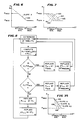
- FIG. 1 there is illustrated therein a graph of various parameters of heart activity versus time from atrial systole through ventricular systole to diastole. From this graph it will be appreciated that various phenomena occur during heart activity. In this respect, there are changes in aortic pressure, left ventricular pressure, left ventricular volume (right ventricular volume as well) and right ventricular pressure. The changes in these parameters are indicative of ejection time.
- the change in aortic pressure from 01 to C1 is a measure of ejection time E.
- a measure of duration of contraction is the change in left ventricular pressure which is shown as E1 in FIG. 1 and which is proportional to ejection time.
- E1 the change in left ventricular pressure
- E1 the change in left ventricular pressure
- ejection time the time period between opening and closing of the aortic valve.
- the pressure starts to increase and the pulmonary valve opens when the pressure exceeds pulmonary pressure. It reaches a maximum and then decreases until all the blood is ejected from the right ventricle at which time the pulmonary valve closes and the pressure again returns to a minimum or 0.
- the time period between the opening and closing of the pulmonary valve is referred to as the ejection time of the right ventricle which is proportional to the duration of contraction E2 of the right ventricle.
- ejection time is the time period in the left ventricle or in the right ventricle when the volume of blood in the right ventricle or left ventricle changes from a maximum value to a minimum value.
- the time period during this change is equal to ejection time and is indicated as E3 in FIG. 1.
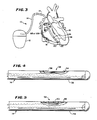
- FIG. 3 is illustrated an apparatus 10 or pacer system 10 which is constructed according to the teachings of the present invention and which includes an implanted pacer or artificial pacemaker 12.
- the pacer 12 has a pulse generator therein and associated cardiac excitation and cardiac activity detection circuitry as well as control circuitry.
- the pacer 12 is connected to a pacing lead 14 at the proximal end thereof.
- the pacing lead extends pervenously into the right ventricle 16 of a heart 18 where a tip electrode 20 at the distal end thereof engages the apex 22 of the right ventricle for detecting cardiac activity and for stimulating the right ventricle 16.
- a pressure sensor 24 is also mounted on the lead 14 and located in the right ventricle just above the tip electrode.
- the sensor can be connected to sensor amplifiers and detection circuitry in the pacer 12 as will be described in greater detail hereinafter.
- the pacer system 10 controls the pacing rate of the pacer 12 relative to ejection time of the right ventricle as determined from determinations of duration of heart contraction.
- pacing system 10 When a patient with sinus node disease has a pacing system implanted within his or her body with the pacing lead 14 implanted in a ventricle of the heart, particularly the right ventricle, such pacing system 10 stimulates the ventricle through the tip electrode 20 at a preset rate. In patients with sinus node disease the heart has lost the ability to increase ventricular rate with exercise. However, the heart continues to increase its dynamic contraction.
- the right ventricular pressure is continuously sensed by the pressure sensor 24 and this pressure and changes in the pressure sensed are used for determining the duration of contraction. From the duration of contraction, changes are determined which parallel changes in ejection time. Then changes in ejection time coupled with sensing of heart activity are used to control the rate of application of pulses to the electrode 20, which rate is referred to as the pacer rate.
- the continuous change in right ventricular pressure is used to determine the duration of contraction, changes in duration of contraction, ejection time and changes in ejection time over time which are then used as a measure of exercise level. Every exercise level has its corresponding heart rate.
- the appropriate heart/pacer rate can be determined.
- a pacer 12 can be adapted to exercise. More specifically, the rate of pulse generation or pacer rate can be controlled so that the pacing system 10 can be adapted relative to ejection time and changes in ejection time over time for exercise when an individual engages in exercise.
- the frequency of the heart rate of a normal heart can be correlated to right ventricular ejection time and changes in ejection time over time as determined by continuous measurement of the right ventricular pressure over time while an individual is exercising and such correlation is generally linear as shown by the slope 30 of the graph of changes in ejection time, ⁇ ET, versus changes in heart rate or pacer rate, ⁇ R, as shown in FIG. 2.
- this relationship between the change in ejection time as determined from changes in right ventricular pressure to the change in heart rate for a normal heart can be programmed in the form of an algorithm in the memory of the microprocessor or any other control circuitry mounted within the pacer 12.
- the system 10 requires the pressure sensor 24 in the implanted pacing lead 14 and the electronic circuitry in microprocessor based pacer 12 for calculating the required change in rate based on the pressure change and the algorithm stored in the memory to cause the control circuitry to change the pacer rate.
- the pacer 12 will have a differential circuit or algorithm incorporated therein. Use of the changes in the ejection time signal avoids DC drift because ⁇ ET is an AC signal.
- the measure of ejection time referred to above is the ejection time of the right ventricle, which is derived from the duration of contraction, E3 in FIG. 1, which is determined from changes in right ventricular pressure.
- the pressure sensor 24 can be defined or realized by a number of different types of pressure sensing elements.
- the pressure sensor may be a hermetically sealed absolute strain gauge transducer or a piezoresistive transducer. Also a fiber optic type pressure sensor can be utilized.
- the pressure sensor 24 is realized by a piezoresistive microelectronic transducer 32 which is fixed within or on the inside of a wall 34 of a tubular sheath 35 of the lead 14 beneath an opening 36 in the sheath 35 as best shown in FIG. 4.
- the transducer 32 can be mounted on a glass carrier and four wire conductors are then coupled to the glass carrier for connection to the transducer 32.
- the four wire conductors are connected to a bridge comprised of variable piezoresistors of the transducer 32.
- the transducer 32 comprises the four resistors electrically connected in the bridge circuit. A voltage is applied across two corners of the bridge via two sensor wire conductors. Then, the voltage across the other two corners of the bridge is sensed, i.e. by the voltage across the other two sensor wire conductors.
- a pressure sensor 24 having an impedance of approximately 1 k ohm requires 1-5 Volt excitation which translates to approximately 1-5 mA current flow.
- One to five mA is too much current drain for the battery power source for the pacemaker 12.
- voltage and current pulses with a 1:200 duty cycle are utilized and supplied to and received from the bridge circuit whereby the current drain is reduced to an acceptable value of approximately 5 microamps.
- the sampling frequency relative to pulse duration has to be chosen in such a way as to minimize current drain and still yield a reproducible pressure curve such as by utilizing the Shannon-Nyquist theorem of sampling.
- the right ventricular systolic pressure will vary with heart rate or pacer rate.
- the first step in utilizing the apparatus 10 involves sensing of changes in the right ventricular pressure.
- a general filtering principle or an N-point averaging technique is employed.
- an N number of samples between 1 and 10, for example, are made and the average is chosen as the sampled pressure,P.
- this average is compared with the previously stored average of the pressure value to determine whether there has been a change.
- P x P x - (P x -1), (P x -1) - (P x-2 ) and (P x -2) - (P x-3 ).
- ⁇ P P x - (P x-1 ) and that is stored in the microprocessor within the pacer 12. Then from changes in pressure and particularly determinations of when the pressure starts to increase from a minimum or zero and decreases to and stops at a minimum or zero, the microprocessor can determine duration of contraction and therefore ejection time. Subsequently changes in ejection time are determined for use in calculating the desired heart/pacer rate and, if necessary, to initiate pacing pulses to maintain a desired pacer rate.
- a transducer 52 comprising a strain gauge 53 mounted within a tubular sheath 54 of a pacing lead 14 and secured to the wall 55 of the sheath 54. Bending of the lead by contraction determined by the strain gauge 53 is then used to determine duration of contraction and therefore ejection time and changes in ejection time. Bending of the lead by contraction can also be measured by a piezo crystal or any other piezoelectric material. This has the advantage that contrary to a pressure transducer or a strain gauge, this type of sensor material does not require an excitation voltage but generates its own output voltage.
- the algorithm or routine in its simplest form relates ⁇ R, which is the change in rate of pulses emitted by the pacer 12, to ⁇ ET, which is the change in ejection time.
- ⁇ R which is the change in rate of pulses emitted by the pacer 12
- ⁇ ET which is the change in ejection time.
- the signal ⁇ P serves as an input to the microprocessor in the pacer 12 for calculating ejection time ET and to determine ⁇ ET for changing the pacer rate frequency as a function of ⁇ ET.
- an algorithm relationship of ⁇ ET to ⁇ R is stored in the memory of the microprocessor in the pacer 12 and provides the algorithm, i.e., slope 30, and the equation therefor, which is utilized by the control circuitry.
- the control circuitry can be caused to exit the program or routine and convert the pacer to its standard non-exercise responsive function. Furthermore, if the pressure shows oscillation without exercise, the number N in the N-point averaging can be programmed or changed to a higher value and the circuitry for sensing or detecting a change in pressure can be programmed to take more samplings of differences before it decides that a change in pressure, ⁇ P, has occurred.
- the advantage of utilizing duration of contraction or ejection time of the right ventricle resides in the fact that the change in right ventricular pressure is directly proportional to the sympathetic nerve activity and exercise activity. That is to say, in a normal human being, right ventricular contraction duration and right ventricular ejection time changes appear to be inversely proportional to exercise without any time lag. This has an advantage over metabolic changes such as pH, oxygen saturation, etc., all of which occur at a time subsequent to the onset of exercise. Therefore, by utilizing the right ventricular pressure to determine ejection time, a pacer directly follows exercise rather than lagging exercise.
- a number of lines 101-104 parallel to and on either side of the line or graph 100 are programmed in the microprocessor so that the pacer 12 can function along the family of lines 100-104.
- the minimum ejection time at which rate changes start can be programmed, which is essential because every patient has his/her own at rest ejection time. Note that this permits values of ejection time to be stored which are greater than ET Prog.Max and less than ET Prog.Min. .
- This formula or algorithm is then utilized in the routine or program carried out by the microprocessor in the pacer 12.
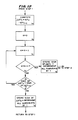
- This routine is set forth in the flow chart shown in FIG. 8.
- the heart pacing rate and ejection time values stored in the pacer 12 are constrained to vary along the line 100 (or 101, 102, 106 or 108) delineated by the above equation having the slope "A" (or A1 or A2) as determined for the patient. That is to say, even if the measured ejection time ET exceeds the programmed maximum ejection time, ET Prog.Max. , that value of ET will be stated as ET Prog.Max. . This is required because the pacer 12 has upper and lower pacing rate limits as set by the physician and the pacer 12 cannot go above or below these pacing rate limits.
- R T-1 is a calculated number. Again, after R T-1 has been replaced by the closest programmable value of R T and ET T-1 has been replaced by ET T , the microprocessor returns to STEP 1 and continues to control pacing rate relative to ejection time.
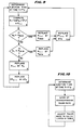
- STEPS 1-10 are essentially the same as STEPS 1-10 in the flow chart shown in FIG. 8.
- STEPS 5 and 8 have been modified from STEPS 5 and 8 in the flow chart shown in FIG. 8 and this permits values of ejection time to be stored which are greater than ET Prog.Max. and less than ET Prog.Min. .
- ET Prog.Max. and ET Prog.Min. have no meaning. This allows for sensor drift and movement of the lines or curves of the graph shown in FIG. 7.
- ET is stored as ET T-1 .
- STEP 10 can be combined with STEPS 5 and 8 as shown in FIG. 9.
- FIG. 10 there is set forth a simple flow chart which utilizes a look-up table of right ventricular ejection time versus heart/pacer rate suitable for both linear and non-linear relationships between heart/pacer rate and ejection time.
- the microprocessor loops back to STEP 1 and continues to determine ejection time.
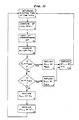
- FIG. 11 is illustrated a flow chart of another program or routine which is analogous to the routine and flow chart therefor shown in FIG. 9.
- this routine compensation for pressure sensor drift is provided by using a look-up table for the change in ejection time and not the actual value of ejection time as determined from changes in pressure (right ventricular pressure).
- the steps of this program are as follows:
- the pacer rate changes may be smoothed by smoothing the changes in ejection time. This can be done in several ways.
- Another approach to smoothing would be to use the subroutine shown in FIG. 12 except to change the pacer rate based upon the average value of ⁇ ET over the N most recent samples if no sign change has occurred.
- FIG. 13 there is illustrated a distal end portion 110 of a pacing lead 112.
- the distal end portion 110 has a tip electrode 114 similar to the tip electrode 20 shown in FIG. 3.
- the distal end portion 110 is further provided with a first ring electrode 116 which is spaced a short distance behind the tip electrode 114 and a second ring electrode 118 spaced further back from the first ring electrode 116.
- the ring electrodes 116 and 118, the tip electrode 114 and the pacer can 12 are utilized to measure impedance between the electrodes 116 and 118 through blood in a ventricle such as the right ventricle at any one of several frequencies by the so-called four electrode method. Current is injected between the pacer can 12 and the tip electrode 114. The voltage measured between ring electrodes 116 and 118 is then proportional to impedance.
- this measure of impedance is stored in the memory of the microprocessor and after a short period of time a second measurement is made. Changes in the impedance are indicative of and correlated to changes in volume of blood in the right ventricle. At the highest volume, the pulmonary valve opens and at the lowest volume the pulmonary valve closes.
- the time of these points of high volume and low volume are noted and the difference in time is the ejection time. Then during exercise the ejection time will change and the changes in ejection time are utilized by the microprocessor in the pacer 12 to control the pacer rate determined by the ejection times determined, in the manner described above and as illustrated in FIGS. 8-12.
- a distal end portion 120 of a pacing lead 122 can be formed in the manner shown in FIG. 14.
- a tip electrode 124 is provided and only one ring electrode 128 spaced a significant distance behind the tip electrode 124.
- the tip electrode 124 will still be used for supplying pacing signals to the apex of a ventricle while the ring electrode 128 is used with the tip electrode 124 for measuring impedance.
- a current at any one of several frequencies is injected between electrode 128 and tip electrode 124. At the same time the voltage between those electrodes 128 and 124 is measured and is proportional to impedance.
- each of the electrodes for measuring impedance in the right ventricle namely electrodes 116 and 118 or 124 and 128 are received in the ventricle as shown in phantom in FIG. 3. Also, the proximal ring electrode 118 and 128 will be disposed just beneath the tricuspid valve.
- the apparatus 10 of the present invention and the method for using same of the present invention enable one to adjust pacer rate in a pacing system relative to ejection time of the right ventricle during exercise with little or no time lag in the adjustment of the pacing rate relative to exercise level.
- the ejection time can be determined first by measuring pressure in the right ventricle at different points in time and determining the time period between minimum levels of pressure to determine duration of contraction. Then determination of changes in the ejection time from changes in duration of contraction will indicate exercise and a new ejection time typically a decreased ejection time indicating that the patient is engaging in exercise, will cause the microprocessor and/or other control circuitry of an implanted pacer to change the pacer rate.
- impedance between two electrodes in the right ventricle can be measured continuously to determine changes in volume of blood in the right ventricle to determine opening and closing of the pulmonary valve to determine ejection time. Then changes in the ejection time, such as a decrease in ejection time, determined in the above manner, can be used to determine the appropriate pacer rate and the pacer rate can be adjusted accordingly. Also, from the foregoing description, it will be apparent that the apparatus 10 of the present invention and the method for using same described above have a number of advantages, some of which have been described above and others of which are inherent in the invention.
- the apparatus 10 allows an implanted pacer system to mimic a change in heart rate that would normally occur in a healthy heart when the individual is exercising and his heart is not naturally changing the pacing rate thereof due to some heart malfunction such as sinus node disease.
- Such apparatus or pacer system 10 will have very little time lag relative to the exercise activity and responds quickly to a need for a changed pacer rate.
Landscapes
- Health & Medical Sciences (AREA)
- Cardiology (AREA)
- Heart & Thoracic Surgery (AREA)
- Life Sciences & Earth Sciences (AREA)
- General Health & Medical Sciences (AREA)
- Public Health (AREA)
- Nuclear Medicine, Radiotherapy & Molecular Imaging (AREA)
- Radiology & Medical Imaging (AREA)
- Engineering & Computer Science (AREA)
- Animal Behavior & Ethology (AREA)
- Hematology (AREA)
- Biomedical Technology (AREA)
- Veterinary Medicine (AREA)
- Biophysics (AREA)
- Physiology (AREA)
- Chemical & Material Sciences (AREA)
- Chemical Kinetics & Catalysis (AREA)
- General Chemical & Material Sciences (AREA)
- Vascular Medicine (AREA)
- Electrotherapy Devices (AREA)
Priority Applications (1)
| Application Number | Priority Date | Filing Date | Title |
|---|---|---|---|
| DE8686111600T DE3688195T2 (de) | 1985-04-11 | 1986-08-21 | Geraet und methode zur einstellung des rhythmus eines herzschrittmachers in bezug auf die auswurfszeit zur erzielung der erforderlichen herzleistung. |
Applications Claiming Priority (1)
| Application Number | Priority Date | Filing Date | Title |
|---|---|---|---|
| US06/722,575 US4716887A (en) | 1985-04-11 | 1985-04-11 | Apparatus and method for adjusting heart/pacer rate relative to cardiac pCO2 to obtain a required cardiac output |
Publications (2)
| Publication Number | Publication Date |
|---|---|
| EP0257116A1 true EP0257116A1 (fr) | 1988-03-02 |
| EP0257116B1 EP0257116B1 (fr) | 1993-03-31 |
Family
ID=24902431
Family Applications (1)
| Application Number | Title | Priority Date | Filing Date |
|---|---|---|---|
| EP86111600A Expired - Lifetime EP0257116B1 (fr) | 1985-04-11 | 1986-08-21 | Appareil et méthode d'ajustement du rythme du coeur ou de stimulateur en fonction du temps d'éjection en vue d'obtenir le fonctionnement cardiaque |
Country Status (3)
| Country | Link |
|---|---|
| US (2) | US4716887A (fr) |
| EP (1) | EP0257116B1 (fr) |
| DE (1) | DE3688195T2 (fr) |
Cited By (15)
| Publication number | Priority date | Publication date | Assignee | Title |
|---|---|---|---|---|
| EP0310026A3 (en) * | 1987-09-28 | 1990-04-11 | Eckhard Dr. Alt | Cardiac and pulmonary physiological analysis via intracardiac measurements with a single sensor |
| EP0317065A3 (en) * | 1987-10-06 | 1990-08-22 | Todd J. Cohen | Hemodynamically responsive system for and method of treating a malfunctioning heart |
| US4966146A (en) * | 1988-01-14 | 1990-10-30 | Webb Stuart C | Rate-responsive pacemaker |
| US5044365A (en) * | 1988-02-17 | 1991-09-03 | Webb Stuart C | Rate-responsive pacemaker |
| EP0461539A3 (en) * | 1990-06-13 | 1992-05-13 | Siemens Elema Ab | Electrode assembly for defibrillator |
| EP0532149A1 (fr) * | 1991-06-17 | 1993-03-17 | Raul Chirife | Entraîneur sensible à fréquence contrôlé par temps de contraction isovolumique |
| EP0532148A1 (fr) * | 1991-06-15 | 1993-03-17 | Raul Chirife | Stimulateur cardiaque à fréquence adaptée controlé par la fraction d'éjection |
| US5438987A (en) * | 1991-06-14 | 1995-08-08 | Pacesetter, Inc. | Implantable lead for sensing a physiologic parameter of the body |
| WO1998017190A3 (fr) * | 1996-10-23 | 1998-10-22 | Oratec Interventions Inc | Procede et appareil de traitement de disques intervertebraux |
| US6419709B1 (en) | 1998-10-02 | 2002-07-16 | Guilford Pharmaceuticals, Inc. | Biodegradable terephthalate polyester-poly(Phosphite) compositions, articles, and methods of using the same |
| US6645203B2 (en) | 1997-02-12 | 2003-11-11 | Oratec Interventions, Inc. | Surgical instrument with off-axis electrode |
| EP1459692A1 (fr) * | 1996-10-23 | 2004-09-22 | Oratec Interventions, Inc. | Procede et appareil de traitement de disques intervertebraux |
| US6997941B2 (en) | 1996-08-13 | 2006-02-14 | Oratec Interventions, Inc. | Method and apparatus for treating annular fissures in intervertebral discs |
| US7069087B2 (en) | 2000-02-25 | 2006-06-27 | Oratec Interventions, Inc. | Apparatus and method for accessing and performing a function within an intervertebral disc |
| US7150747B1 (en) | 2003-01-22 | 2006-12-19 | Smith & Nephew, Inc. | Electrosurgical cutter |
Families Citing this family (119)
| Publication number | Priority date | Publication date | Assignee | Title |
|---|---|---|---|---|
| DE3506791A1 (de) * | 1985-02-22 | 1986-08-28 | Biotronik Meß- und Therapiegeräte GmbH & Co Ingenieurbüro Berlin, 1000 Berlin | Herzschrittmacher mit physiologischer steuerung |
| EP0249822B1 (fr) * | 1986-06-16 | 1991-10-16 | Siemens Aktiengesellschaft | Stimulateur cardiaque contrôlé en fréquence |
| SE8702523D0 (sv) * | 1987-06-17 | 1987-06-17 | Siemens Elema Ab | Rate responsive pacemaker |
| US5027816A (en) * | 1987-10-06 | 1991-07-02 | Leonard Bloom | Hemodynamically responsive system for and method of treating a malfunctioning heart |
| US4901725A (en) * | 1988-01-29 | 1990-02-20 | Telectronics N.V. | Minute volume rate-responsive pacemaker |
| US4865036A (en) * | 1988-06-10 | 1989-09-12 | Raul Chirife | Antitachyarrythmia pacemaker using pre-ejection period to distinguish physiologic from pathologic tachycardia |
| EP0347708A1 (fr) * | 1988-06-16 | 1989-12-27 | Cardiac Pacemakers, Inc. | Détection hémodynamique de tachyarhythmies |
| US5456251A (en) | 1988-08-26 | 1995-10-10 | Mountpelier Investments, S.A. | Remote sensing tonometric catheter apparatus and method |
| US4972834A (en) * | 1988-09-30 | 1990-11-27 | Vitatron Medical B.V. | Pacemaker with improved dynamic rate responsiveness |
| US4928689A (en) * | 1989-05-15 | 1990-05-29 | Cardiac Pacemakers, Inc. | Rate adaptive cardiac pacer system having living cell tissue for sensing physiologic demand |
| US5052388A (en) * | 1989-12-22 | 1991-10-01 | Medtronic, Inc. | Method and apparatus for implementing activity sensing in a pulse generator |
| US5179946A (en) * | 1989-12-28 | 1993-01-19 | Telectronics Pacing Systems, Inc. | Apparatus and method for arrhythmia detection by variations in the transcardiac impedance between defibrillation patches |
| US5054485A (en) * | 1990-06-01 | 1991-10-08 | Leonard Bloom | Hemodynamically responsive system for and method of treating a malfunctioning heart |
| US5085213A (en) * | 1990-06-01 | 1992-02-04 | Leonard Bloom | Hemodynamically responsive system for and method of treating a malfunctioning heart |
| US5058583A (en) * | 1990-07-13 | 1991-10-22 | Geddes Leslie A | Multiple monopolar system and method of measuring stroke volume of the heart |
| FR2671012B1 (fr) * | 1990-12-27 | 1993-03-19 | Ela Medical Sa | Procede de controle d'un stimulateur cardiaque. |
| EP0494787B1 (fr) * | 1991-01-09 | 1996-03-27 | Medtronic, Inc. | Servocommande pour muscles |
| US5207226A (en) * | 1991-01-25 | 1993-05-04 | Regents Of The University Of Minnesota | Device and method for measurement of blood flow |
| US5174303A (en) * | 1991-05-03 | 1992-12-29 | Intermedics, Inc. | Pacer lead with replaceable sensor |
| US5213098A (en) * | 1991-07-26 | 1993-05-25 | Medtronic, Inc. | Post-extrasystolic potentiation stimulation with physiologic sensor feedback |
| US5193535A (en) * | 1991-08-27 | 1993-03-16 | Medtronic, Inc. | Method and apparatus for discrimination of ventricular tachycardia from ventricular fibrillation and for treatment thereof |
| DE69213657T2 (de) * | 1991-11-04 | 1997-01-23 | Cardiac Pacemakers | Implantierbares Gerät zur Überwachung und Stimulation des Herzens für Diagnose und Therapie |
| US5235976A (en) * | 1991-12-13 | 1993-08-17 | Cardiac Pacemakers, Inc. | Method and apparatus for managing and monitoring cardiac rhythm using active time as the controlling parameter |
| US5330513A (en) * | 1992-05-01 | 1994-07-19 | Medtronic, Inc. | Diagnostic function data storage and telemetry out for rate responsive cardiac pacemaker |
| SE9202937D0 (sv) * | 1992-10-07 | 1992-10-07 | Siemens Elema Ab | Frekvensadaptiv hjaertstimulator |
| US5334222A (en) * | 1992-11-03 | 1994-08-02 | Cardiac Pacemakers, Inc. | Cardiac stimulating apparatus and method for heart failure therapy |
| US5497778A (en) * | 1993-06-30 | 1996-03-12 | Hon; Edward H. | Apparatus and method for noninvasive measurement of peripheral pressure pulse compliance and systolic time intervals |
| SE9303736D0 (sv) * | 1993-11-12 | 1993-11-12 | Siemens Elema Ab | Apparat avsedd att avkänna fysiskt tillstånd för ett levande väsen |
| US5409009A (en) * | 1994-03-18 | 1995-04-25 | Medtronic, Inc. | Methods for measurement of arterial blood flow |
| WO1995027531A1 (fr) * | 1994-04-08 | 1995-10-19 | Pacesetter, Inc. | Stimulateur cardiaque a commande physiologique et son procede |
| US5458596A (en) | 1994-05-06 | 1995-10-17 | Dorsal Orthopedic Corporation | Method and apparatus for controlled contraction of soft tissue |
| US6461353B1 (en) | 1995-02-17 | 2002-10-08 | Oratec Interventions, Inc. | Orthopedic apparatus for controlled contraction of collagen tissue |
| US6073048A (en) * | 1995-11-17 | 2000-06-06 | Medtronic, Inc. | Baroreflex modulation with carotid sinus nerve stimulation for the treatment of heart failure |
| US5674256A (en) * | 1995-12-19 | 1997-10-07 | Cardiac Pacemakers, Inc. | Cardiac pre-ejection period detection |
| US5626623A (en) * | 1996-04-30 | 1997-05-06 | Medtronic, Inc. | Method and apparatus for optimizing pacemaker AV delay |
| DE19621996C2 (de) * | 1996-05-31 | 1998-04-09 | Siemens Ag | Verfahren zur Herstellung einer Kombination eines Drucksensors und eines elektrochemischen Sensors |
| US6832997B2 (en) | 2001-06-06 | 2004-12-21 | Oratec Interventions, Inc. | Electromagnetic energy delivery intervertebral disc treatment devices |
| US6733496B2 (en) | 2001-06-06 | 2004-05-11 | Oratec Interventions, Inc. | Intervertebral disc device employing flexible probe |
| US6726685B2 (en) | 2001-06-06 | 2004-04-27 | Oratec Interventions, Inc. | Intervertebral disc device employing looped probe |
| SE9602979D0 (sv) * | 1996-08-14 | 1996-08-14 | Pacesetter Ab | Pacemaker |
| US5782884A (en) * | 1996-11-05 | 1998-07-21 | Sulzer Intermedics Inc. | Rate responsive cardiac pacemaker with peak impedance detection for rate control |
| US5700283A (en) * | 1996-11-25 | 1997-12-23 | Cardiac Pacemakers, Inc. | Method and apparatus for pacing patients with severe congestive heart failure |
| AU6156198A (en) | 1997-02-12 | 1998-08-26 | Oratec Interventions, Inc. | Concave probe for arthroscopic surgery |
| US5919210A (en) * | 1997-04-10 | 1999-07-06 | Pharmatarget, Inc. | Device and method for detection and treatment of syncope |
| US6176857B1 (en) | 1997-10-22 | 2001-01-23 | Oratec Interventions, Inc. | Method and apparatus for applying thermal energy to tissue asymmetrically |
| US6314322B1 (en) | 1998-03-02 | 2001-11-06 | Abiomed, Inc. | System and method for treating dilated cardiomyopathy using end diastolic volume (EDV) sensing |
| JP2002506672A (ja) | 1998-03-19 | 2002-03-05 | オーレイテック インターヴェンションズ インコーポレイテッド | 手術部位にエネルギーを給送するためのカテーテル |
| US6600949B1 (en) * | 1999-11-10 | 2003-07-29 | Pacesetter, Inc. | Method for monitoring heart failure via respiratory patterns |
| US7194371B1 (en) * | 2000-03-27 | 2007-03-20 | Cardiobeat.Com | Medical testing system and method |
| US6589188B1 (en) | 2000-05-05 | 2003-07-08 | Pacesetter, Inc. | Method for monitoring heart failure via respiratory patterns |
| SE0002514D0 (sv) * | 2000-06-30 | 2000-06-30 | Pacesetter Ab | Medical device |
| US6741885B1 (en) | 2000-12-07 | 2004-05-25 | Pacesetter, Inc. | Implantable cardiac device for managing the progression of heart disease and method |
| US6695839B2 (en) | 2001-02-08 | 2004-02-24 | Oratec Interventions, Inc. | Method and apparatus for treatment of disrupted articular cartilage |
| AU2002240363A1 (en) * | 2001-02-13 | 2002-08-28 | Quetzal Biomedical, Inc. | Multi-electrode apparatus and method for treatment of congestive heart failure |
| US6580946B2 (en) * | 2001-04-26 | 2003-06-17 | Medtronic, Inc. | Pressure-modulated rate-responsive cardiac pacing |
| US6638276B2 (en) | 2001-06-06 | 2003-10-28 | Oratec Interventions, Inc. | Intervertebral disc device employing prebent sheath |
| US6695790B2 (en) | 2001-10-26 | 2004-02-24 | Medtronic, Inc. | Method and system for determining kidney failure |
| US20050027323A1 (en) * | 2001-10-30 | 2005-02-03 | Medtronic, Inc. | Implantable medical device for monitoring cardiac blood pressure and chamber dimension |
| US6959214B2 (en) | 2001-11-28 | 2005-10-25 | Medtronic, Inc. | Implantable medical device for measuring mechanical heart function |
| US7058450B2 (en) * | 2002-04-22 | 2006-06-06 | Medtronic, Inc. | Organizing data according to cardiac rhythm type |
| US7164948B2 (en) * | 2002-04-22 | 2007-01-16 | Medtronic, Inc. | Cardiac output measurement using dual oxygen sensors in right and left ventricles |
| US7149568B2 (en) * | 2002-07-12 | 2006-12-12 | Seiko Epson Corporation | Exercise load intensity evaluation device and exercise equipment |
| US6909919B2 (en) * | 2002-09-06 | 2005-06-21 | Cardiac Pacemakers, Inc. | Cardiac lead incorporating strain gauge for assessing cardiac contractility |
| US7139613B2 (en) * | 2002-09-25 | 2006-11-21 | Medtronic, Inc. | Implantable medical device communication system with pulsed power biasing |
| US7013178B2 (en) * | 2002-09-25 | 2006-03-14 | Medtronic, Inc. | Implantable medical device communication system |
| US7207947B2 (en) * | 2003-01-10 | 2007-04-24 | Pacesetter, Inc. | System and method for detecting circadian states using an implantable medical device |
| US7383071B1 (en) * | 2003-04-25 | 2008-06-03 | United States Of America As Represented By The Secretary Of The Navy | Microsensor system and method for measuring data |
| US7297113B1 (en) * | 2003-04-25 | 2007-11-20 | United States Of America As Represented By The Secretary Of The Navy | Microsensor system and method for measuring data |
| US7657312B2 (en) | 2003-11-03 | 2010-02-02 | Cardiac Pacemakers, Inc. | Multi-site ventricular pacing therapy with parasympathetic stimulation |
| US7239915B2 (en) * | 2003-12-16 | 2007-07-03 | Medtronic, Inc. | Hemodynamic optimization system for biventricular implants |
| US8024050B2 (en) * | 2003-12-24 | 2011-09-20 | Cardiac Pacemakers, Inc. | Lead for stimulating the baroreceptors in the pulmonary artery |
| US7509166B2 (en) | 2003-12-24 | 2009-03-24 | Cardiac Pacemakers, Inc. | Automatic baroreflex modulation responsive to adverse event |
| US7869881B2 (en) * | 2003-12-24 | 2011-01-11 | Cardiac Pacemakers, Inc. | Baroreflex stimulator with integrated pressure sensor |
| US8126560B2 (en) * | 2003-12-24 | 2012-02-28 | Cardiac Pacemakers, Inc. | Stimulation lead for stimulating the baroreceptors in the pulmonary artery |
| US7668594B2 (en) | 2005-08-19 | 2010-02-23 | Cardiac Pacemakers, Inc. | Method and apparatus for delivering chronic and post-ischemia cardiac therapies |
| US7286884B2 (en) | 2004-01-16 | 2007-10-23 | Medtronic, Inc. | Implantable lead including sensor |
| US20050159801A1 (en) * | 2004-01-16 | 2005-07-21 | Medtronic, Inc. | Novel implantable lead including sensor |
| US7223244B1 (en) | 2004-05-18 | 2007-05-29 | Pacesetter, Inc. | System and method for monitoring hypercapnic ventilatory response |
| US7295874B2 (en) * | 2005-01-06 | 2007-11-13 | Cardiac Pacemakers, Inc. | Intermittent stress augmentation pacing for cardioprotective effect |
| US7775966B2 (en) | 2005-02-24 | 2010-08-17 | Ethicon Endo-Surgery, Inc. | Non-invasive pressure measurement in a fluid adjustable restrictive device |
| US8066629B2 (en) | 2005-02-24 | 2011-11-29 | Ethicon Endo-Surgery, Inc. | Apparatus for adjustment and sensing of gastric band pressure |
| US7699770B2 (en) | 2005-02-24 | 2010-04-20 | Ethicon Endo-Surgery, Inc. | Device for non-invasive measurement of fluid pressure in an adjustable restriction device |
| US8016744B2 (en) | 2005-02-24 | 2011-09-13 | Ethicon Endo-Surgery, Inc. | External pressure-based gastric band adjustment system and method |
| US7927270B2 (en) | 2005-02-24 | 2011-04-19 | Ethicon Endo-Surgery, Inc. | External mechanical pressure sensor for gastric band pressure measurements |
| US7775215B2 (en) | 2005-02-24 | 2010-08-17 | Ethicon Endo-Surgery, Inc. | System and method for determining implanted device positioning and obtaining pressure data |
| US7658196B2 (en) | 2005-02-24 | 2010-02-09 | Ethicon Endo-Surgery, Inc. | System and method for determining implanted device orientation |
| US7765000B2 (en) * | 2005-05-10 | 2010-07-27 | Cardiac Pacemakers, Inc. | Neural stimulation system with pulmonary artery lead |
| US7734348B2 (en) * | 2005-05-10 | 2010-06-08 | Cardiac Pacemakers, Inc. | System with left/right pulmonary artery electrodes |
| US7850616B1 (en) * | 2005-06-15 | 2010-12-14 | Pacesetter, Inc. | Determination of diastolic heart failure |
| US8870742B2 (en) | 2006-04-06 | 2014-10-28 | Ethicon Endo-Surgery, Inc. | GUI for an implantable restriction device and a data logger |
| US8152710B2 (en) | 2006-04-06 | 2012-04-10 | Ethicon Endo-Surgery, Inc. | Physiological parameter analysis for an implantable restriction device and a data logger |
| US20080195167A1 (en) * | 2006-12-29 | 2008-08-14 | Ryan Timothy J | Cardiac pacemakers and systems and methods for using them |
| US20100113945A1 (en) * | 2006-12-29 | 2010-05-06 | Ryan Timothy J | Hemodynamic monitors and systems and methods for using them |
| US8615296B2 (en) * | 2007-03-06 | 2013-12-24 | Cardiac Pacemakers, Inc. | Method and apparatus for closed-loop intermittent cardiac stress augmentation pacing |
| US8187163B2 (en) | 2007-12-10 | 2012-05-29 | Ethicon Endo-Surgery, Inc. | Methods for implanting a gastric restriction device |
| CN101939048B (zh) | 2007-12-12 | 2015-06-17 | 心脏起搏器股份公司 | 用于从肺动脉递送神经刺激的系统 |
| US8100870B2 (en) | 2007-12-14 | 2012-01-24 | Ethicon Endo-Surgery, Inc. | Adjustable height gastric restriction devices and methods |
| US8377079B2 (en) | 2007-12-27 | 2013-02-19 | Ethicon Endo-Surgery, Inc. | Constant force mechanisms for regulating restriction devices |
| US8142452B2 (en) | 2007-12-27 | 2012-03-27 | Ethicon Endo-Surgery, Inc. | Controlling pressure in adjustable restriction devices |
| US8192350B2 (en) | 2008-01-28 | 2012-06-05 | Ethicon Endo-Surgery, Inc. | Methods and devices for measuring impedance in a gastric restriction system |
| US8591395B2 (en) | 2008-01-28 | 2013-11-26 | Ethicon Endo-Surgery, Inc. | Gastric restriction device data handling devices and methods |
| US8337389B2 (en) | 2008-01-28 | 2012-12-25 | Ethicon Endo-Surgery, Inc. | Methods and devices for diagnosing performance of a gastric restriction system |
| US8548586B2 (en) * | 2008-01-29 | 2013-10-01 | Cardiac Pacemakers, Inc. | Configurable intermittent pacing therapy |
| US7844342B2 (en) | 2008-02-07 | 2010-11-30 | Ethicon Endo-Surgery, Inc. | Powering implantable restriction systems using light |
| US8221439B2 (en) | 2008-02-07 | 2012-07-17 | Ethicon Endo-Surgery, Inc. | Powering implantable restriction systems using kinetic motion |
| US8114345B2 (en) | 2008-02-08 | 2012-02-14 | Ethicon Endo-Surgery, Inc. | System and method of sterilizing an implantable medical device |
| US8591532B2 (en) | 2008-02-12 | 2013-11-26 | Ethicon Endo-Sugery, Inc. | Automatically adjusting band system |
| US8057492B2 (en) | 2008-02-12 | 2011-11-15 | Ethicon Endo-Surgery, Inc. | Automatically adjusting band system with MEMS pump |
| US8034065B2 (en) | 2008-02-26 | 2011-10-11 | Ethicon Endo-Surgery, Inc. | Controlling pressure in adjustable restriction devices |
| US8233995B2 (en) | 2008-03-06 | 2012-07-31 | Ethicon Endo-Surgery, Inc. | System and method of aligning an implantable antenna |
| US8187162B2 (en) | 2008-03-06 | 2012-05-29 | Ethicon Endo-Surgery, Inc. | Reorientation port |
| US8140155B2 (en) * | 2008-03-11 | 2012-03-20 | Cardiac Pacemakers, Inc. | Intermittent pacing therapy delivery statistics |
| US8483826B2 (en) * | 2008-03-17 | 2013-07-09 | Cardiac Pacemakers, Inc. | Deactivation of intermittent pacing therapy |
| EP2346401B1 (fr) * | 2008-09-30 | 2013-05-22 | St. Jude Medical AB | Détecteur d insuffisance cardiaque |
| US8958873B2 (en) * | 2009-05-28 | 2015-02-17 | Cardiac Pacemakers, Inc. | Method and apparatus for safe and efficient delivery of cardiac stress augmentation pacing |
| US20110034812A1 (en) * | 2009-08-10 | 2011-02-10 | Abhilash Patangay | Pulmonary artery pressure based systolic timing intervals as a measure of right ventricular systolic performance |
| US8812104B2 (en) * | 2009-09-23 | 2014-08-19 | Cardiac Pacemakers, Inc. | Method and apparatus for automated control of pacing post-conditioning |
| US8396563B2 (en) | 2010-01-29 | 2013-03-12 | Medtronic, Inc. | Clock synchronization in an implantable medical device system |
| EP3131502B1 (fr) | 2014-04-16 | 2021-07-21 | Alma Mater Studiorum - Università di Bologna | Prothèse de valvule cardiaque comprenant un circuit électronique intégré destiné à mesurer une impédance électrique intravalvulaire |
Citations (8)
| Publication number | Priority date | Publication date | Assignee | Title |
|---|---|---|---|---|
| US3815611A (en) * | 1971-11-26 | 1974-06-11 | Medtronic Inc | Muscle stimulation and/or contraction detection device |
| FR2403775A1 (fr) * | 1977-09-26 | 1979-04-20 | Zacouto Fred | Procede et dispositifs de controle et d'intervention cardiovasculaire |
| EP0007189A1 (fr) * | 1978-06-23 | 1980-01-23 | Vitafin N.V. | Stimulateur cardiaque se conformant à des conditions physiologiques |
| EP0080347A1 (fr) * | 1981-11-19 | 1983-06-01 | Medtronic, Inc. | Système transducteur de pression dynamique implantable |
| EP0140472A1 (fr) * | 1983-06-30 | 1985-05-08 | Medtronic, Inc. | Stimulateur commandé par le volume systolique |
| EP0178528A1 (fr) * | 1984-10-18 | 1986-04-23 | Telectronics N.V. | Procédé pour ajuster le rythme du coeur/stimulateur à la pression systolique ventriculaire droite pour obtenir la puissance cardiaque requise |
| US4600017A (en) * | 1984-07-19 | 1986-07-15 | Cordis Corporation | Pacing lead with sensor |
| EP0203027A1 (fr) * | 1985-02-22 | 1986-11-26 | BIOTRONIK Mess- und Therapiegeräte GmbH & Co Ingenieurbüro Berlin | Stimulateur cardiaque à la demande avec commande physiologique |
Family Cites Families (25)
| Publication number | Priority date | Publication date | Assignee | Title |
|---|---|---|---|---|
| US3572315A (en) * | 1968-11-26 | 1971-03-23 | John S Cullen | Intravascular catheter with gas-permeable tip |
| US3659586A (en) * | 1969-05-20 | 1972-05-02 | Univ Johns Hopkins | Percutaneous carbon dioxide sensor and process for measuring pulmonary efficiency |
| US3658053A (en) * | 1969-08-28 | 1972-04-25 | Scient Research Instr Corp | Catheter for use in detecting dissolved gas in fluids such as blood |
| US3710778A (en) * | 1971-03-15 | 1973-01-16 | Gen Electric | Blood gas sensor amplifier and testing system |
| US3900382A (en) * | 1974-11-01 | 1975-08-19 | Gen Electric | Miniature probe containing multifunctional electrochemical electrodes |
| IT1028812B (it) * | 1975-04-24 | 1979-02-10 | Alcidi M | Pacemaker artificiale perfezionato |
| CH610665A5 (fr) * | 1976-03-12 | 1979-04-30 | Hoffmann La Roche | |
| DE2717659C2 (de) * | 1977-04-21 | 1985-11-14 | Wirtzfeld, Alexander, Prof. Dr.med., 8195 Egling | Herzschrittmacher |
| US4273636A (en) * | 1977-05-26 | 1981-06-16 | Kiyoo Shimada | Selective chemical sensitive field effect transistor transducers |
| GB2005418B (en) * | 1977-07-26 | 1982-04-21 | Searle & Co | Electrochemical sensor system |
| CH632403A5 (de) * | 1977-09-08 | 1982-10-15 | Avl Ag | Verfahren und einrichtung zum ermitteln von systolischen zeitintervallen. |
| US4133735A (en) * | 1977-09-27 | 1979-01-09 | The Board Of Regents Of The University Of Washington | Ion-sensitive electrode and processes for making the same |
| JPS5466194A (en) * | 1977-11-04 | 1979-05-28 | Kuraray Co | Fet sensor |
| US4291699A (en) * | 1978-09-21 | 1981-09-29 | Purdue Research Foundation | Method of and apparatus for automatically detecting and treating ventricular fibrillation |
| FR2442631A1 (fr) * | 1978-11-30 | 1980-06-27 | Lem Spa | Pacemaker a frequence de stimulation controlee par le ph du sang du porteur |
| JPS5626250A (en) * | 1979-08-10 | 1981-03-13 | Olympus Optical Co Ltd | Composite chemical sensor |
| US4401122A (en) * | 1979-08-02 | 1983-08-30 | Children's Hospital Medical Center | Cutaneous methods of measuring body substances |
| NL8001420A (nl) * | 1980-03-10 | 1981-10-01 | Cordis Europ | Voor een elektrochemische meting toepasbare elektrode omvattend samenstel, in het bijzonder een als een isfet uitgevoerd samenstel, en werkwijze ter vervaardiging van het samenstel. |
| US4450842A (en) * | 1980-04-25 | 1984-05-29 | Cordis Corporation | Solid state reference electrode |
| JPS5740641A (en) * | 1980-08-25 | 1982-03-06 | Kuraray Co Ltd | Gas sensor |
| US4404972B1 (en) * | 1981-05-18 | 2000-07-11 | Intermedics Inc | Implantable device with microprocessor control |
| US4456013A (en) * | 1981-09-08 | 1984-06-26 | Brown University Research Foundation | Catheter |
| US4411741A (en) * | 1982-01-12 | 1983-10-25 | University Of Utah | Apparatus and method for measuring the concentration of components in fluids |
| US4488556A (en) * | 1982-06-03 | 1984-12-18 | Critikon, Inc. | AC Mode operation of chemfet devices |
| JPS59131156A (ja) * | 1983-01-17 | 1984-07-27 | Kuraray Co Ltd | ガスセンサ− |
-
1985
- 1985-04-11 US US06/722,575 patent/US4716887A/en not_active Expired - Lifetime
-
1986
- 1986-08-21 DE DE8686111600T patent/DE3688195T2/de not_active Expired - Fee Related
- 1986-08-21 EP EP86111600A patent/EP0257116B1/fr not_active Expired - Lifetime
- 1986-10-30 US US06/924,764 patent/US4730619A/en not_active Expired - Lifetime
Patent Citations (8)
| Publication number | Priority date | Publication date | Assignee | Title |
|---|---|---|---|---|
| US3815611A (en) * | 1971-11-26 | 1974-06-11 | Medtronic Inc | Muscle stimulation and/or contraction detection device |
| FR2403775A1 (fr) * | 1977-09-26 | 1979-04-20 | Zacouto Fred | Procede et dispositifs de controle et d'intervention cardiovasculaire |
| EP0007189A1 (fr) * | 1978-06-23 | 1980-01-23 | Vitafin N.V. | Stimulateur cardiaque se conformant à des conditions physiologiques |
| EP0080347A1 (fr) * | 1981-11-19 | 1983-06-01 | Medtronic, Inc. | Système transducteur de pression dynamique implantable |
| EP0140472A1 (fr) * | 1983-06-30 | 1985-05-08 | Medtronic, Inc. | Stimulateur commandé par le volume systolique |
| US4600017A (en) * | 1984-07-19 | 1986-07-15 | Cordis Corporation | Pacing lead with sensor |
| EP0178528A1 (fr) * | 1984-10-18 | 1986-04-23 | Telectronics N.V. | Procédé pour ajuster le rythme du coeur/stimulateur à la pression systolique ventriculaire droite pour obtenir la puissance cardiaque requise |
| EP0203027A1 (fr) * | 1985-02-22 | 1986-11-26 | BIOTRONIK Mess- und Therapiegeräte GmbH & Co Ingenieurbüro Berlin | Stimulateur cardiaque à la demande avec commande physiologique |
Cited By (25)
| Publication number | Priority date | Publication date | Assignee | Title |
|---|---|---|---|---|
| EP0310026A3 (en) * | 1987-09-28 | 1990-04-11 | Eckhard Dr. Alt | Cardiac and pulmonary physiological analysis via intracardiac measurements with a single sensor |
| EP0310024A3 (en) * | 1987-09-28 | 1990-04-18 | Eckhard Dr. Alt | Ventilation controlled rate responsive cardiac pacemaker |
| EP0317065A3 (en) * | 1987-10-06 | 1990-08-22 | Todd J. Cohen | Hemodynamically responsive system for and method of treating a malfunctioning heart |
| US4966146A (en) * | 1988-01-14 | 1990-10-30 | Webb Stuart C | Rate-responsive pacemaker |
| US5044365A (en) * | 1988-02-17 | 1991-09-03 | Webb Stuart C | Rate-responsive pacemaker |
| US5063927A (en) * | 1988-02-17 | 1991-11-12 | Webb Stuart C | Rate-responsive pacemaker |
| EP0461539A3 (en) * | 1990-06-13 | 1992-05-13 | Siemens Elema Ab | Electrode assembly for defibrillator |
| US5438987A (en) * | 1991-06-14 | 1995-08-08 | Pacesetter, Inc. | Implantable lead for sensing a physiologic parameter of the body |
| EP0532148A1 (fr) * | 1991-06-15 | 1993-03-17 | Raul Chirife | Stimulateur cardiaque à fréquence adaptée controlé par la fraction d'éjection |
| EP0532149A1 (fr) * | 1991-06-17 | 1993-03-17 | Raul Chirife | Entraîneur sensible à fréquence contrôlé par temps de contraction isovolumique |
| US7267683B2 (en) | 1996-08-13 | 2007-09-11 | Oratec Interventions, Inc. | Method for treating intervertebral discs |
| US7282061B2 (en) | 1996-08-13 | 2007-10-16 | Oratec Interventions, Inc. | Method of treating intervertebral disc |
| US8226697B2 (en) | 1996-08-13 | 2012-07-24 | Neurotherm, Inc. | Method for treating intervertebral disc |
| US8187312B2 (en) | 1996-08-13 | 2012-05-29 | Neurotherm, Inc. | Method for treating intervertebral disc |
| US8128619B2 (en) | 1996-08-13 | 2012-03-06 | Neurotherm, Inc. | Method for treating intervertebral discs |
| US6997941B2 (en) | 1996-08-13 | 2006-02-14 | Oratec Interventions, Inc. | Method and apparatus for treating annular fissures in intervertebral discs |
| US7647123B2 (en) | 1996-08-13 | 2010-01-12 | Oratec Interventions, Inc. | Method for treating intervertebral discs |
| US7400930B2 (en) | 1996-08-13 | 2008-07-15 | Oratec Interventions, Inc. | Method for treating intervertebral discs |
| EP1459691A1 (fr) * | 1996-10-23 | 2004-09-22 | Oratec Interventions, Inc. | Procede et appareil de traitement de disques intervertebraux |
| WO1998017190A3 (fr) * | 1996-10-23 | 1998-10-22 | Oratec Interventions Inc | Procede et appareil de traitement de disques intervertebraux |
| EP1459692A1 (fr) * | 1996-10-23 | 2004-09-22 | Oratec Interventions, Inc. | Procede et appareil de traitement de disques intervertebraux |
| US6645203B2 (en) | 1997-02-12 | 2003-11-11 | Oratec Interventions, Inc. | Surgical instrument with off-axis electrode |
| US6419709B1 (en) | 1998-10-02 | 2002-07-16 | Guilford Pharmaceuticals, Inc. | Biodegradable terephthalate polyester-poly(Phosphite) compositions, articles, and methods of using the same |
| US7069087B2 (en) | 2000-02-25 | 2006-06-27 | Oratec Interventions, Inc. | Apparatus and method for accessing and performing a function within an intervertebral disc |
| US7150747B1 (en) | 2003-01-22 | 2006-12-19 | Smith & Nephew, Inc. | Electrosurgical cutter |
Also Published As
| Publication number | Publication date |
|---|---|
| DE3688195D1 (de) | 1993-05-06 |
| US4730619A (en) | 1988-03-15 |
| DE3688195T2 (de) | 1993-07-08 |
| US4716887A (en) | 1988-01-05 |
| EP0257116B1 (fr) | 1993-03-31 |
Similar Documents
| Publication | Publication Date | Title |
|---|---|---|
| EP0257116B1 (fr) | Appareil et méthode d'ajustement du rythme du coeur ou de stimulateur en fonction du temps d'éjection en vue d'obtenir le fonctionnement cardiaque | |
| EP0178528B1 (fr) | Procédé pour ajuster le rythme du coeur/stimulateur à la pression systolique ventriculaire droite pour obtenir la puissance cardiaque requise | |
| US4770177A (en) | Apparatus and method for adjusting heart/pacer relative to changes in venous diameter during exercise to obtain a required cardiac output. | |
| US4936304A (en) | Pacing system and method for cardiac pacing as a function of determined myocardial contractility | |
| US6256538B1 (en) | Implantable heart stimulator | |
| US5549650A (en) | System and method for providing hemodynamically optimal pacing therapy | |
| EP0307093B1 (fr) | Stimulateur cardiaque pour la stimulation du coeur | |
| US6466821B1 (en) | AC/DC multi-axis accelerometer for determining patient activity and body position | |
| EP1011432B1 (fr) | Detecteur d'ischemie | |
| CA2390016C (fr) | Dispositif implantable de regulation du rythme cardiaque servant a evaluer le statut de patients souffrant d'insuffisance cardiaque globale | |
| US4596251A (en) | Minute ventilation dependent rate responsive pacer | |
| EP0541338B1 (fr) | Appareil implantable de surveillance et de stimulation cardiaque pour diagnostic et thérapie | |
| EP0765671B1 (fr) | Mesure d'impédance transvalvulaire | |
| EP0310024B1 (fr) | Stimulateur cardiaque dont le rythme est contrôlé par la respiration | |
| US5782884A (en) | Rate responsive cardiac pacemaker with peak impedance detection for rate control | |
| US6275727B1 (en) | Implantable cardiac rhythm management device for assessing status of CHF patients | |
| EP0140472B1 (fr) | Stimulateur commandé par le volume systolique | |
| US4827933A (en) | Apparatus and method for adjusting heart/pacer rate relative to cardiac pO2 obtain a required cardiac output | |
| US5578064A (en) | Rate responsive cardiac pacemaker with impedance sensing | |
| US4858611A (en) | Sensing system and method for sensing minute ventilation | |
| EP0191404A1 (fr) | Palpeur de l'activité pour la commande des stimulateurs cardiaques | |
| EP0615770A1 (fr) | Méthode et dispositif pour gérer et contrôler le rythme cardiaque en utilisant comme paramètre de contrôle la "période active" | |
| EP0244446B1 (fr) | Stimulateur myocardiaque sensible a la contractivite |
Legal Events
| Date | Code | Title | Description |
|---|---|---|---|
| PUAI | Public reference made under article 153(3) epc to a published international application that has entered the european phase |
Free format text: ORIGINAL CODE: 0009012 |
|
| AK | Designated contracting states |
Kind code of ref document: A1 Designated state(s): DE FR GB IT NL |
|
| 17P | Request for examination filed |
Effective date: 19880819 |
|
| 17Q | First examination report despatched |
Effective date: 19910424 |
|
| GRAA | (expected) grant |
Free format text: ORIGINAL CODE: 0009210 |
|
| AK | Designated contracting states |
Kind code of ref document: B1 Designated state(s): DE FR GB IT NL |
|
| ITF | It: translation for a ep patent filed | ||
| REF | Corresponds to: |
Ref document number: 3688195 Country of ref document: DE Date of ref document: 19930506 |
|
| ET | Fr: translation filed | ||
| ITTA | It: last paid annual fee | ||
| PLBE | No opposition filed within time limit |
Free format text: ORIGINAL CODE: 0009261 |
|
| STAA | Information on the status of an ep patent application or granted ep patent |
Free format text: STATUS: NO OPPOSITION FILED WITHIN TIME LIMIT |
|
| 26N | No opposition filed | ||
| PGFP | Annual fee paid to national office [announced via postgrant information from national office to epo] |
Ref country code: GB Payment date: 19970821 Year of fee payment: 12 |
|
| PG25 | Lapsed in a contracting state [announced via postgrant information from national office to epo] |
Ref country code: GB Free format text: LAPSE BECAUSE OF NON-PAYMENT OF DUE FEES Effective date: 19980821 |
|
| PGFP | Annual fee paid to national office [announced via postgrant information from national office to epo] |
Ref country code: NL Payment date: 19980831 Year of fee payment: 13 |
|
| GBPC | Gb: european patent ceased through non-payment of renewal fee |
Effective date: 19980821 |
|
| PG25 | Lapsed in a contracting state [announced via postgrant information from national office to epo] |
Ref country code: NL Free format text: LAPSE BECAUSE OF NON-PAYMENT OF DUE FEES Effective date: 20000301 |
|
| NLV4 | Nl: lapsed or anulled due to non-payment of the annual fee |
Effective date: 20000301 |
|
| PGFP | Annual fee paid to national office [announced via postgrant information from national office to epo] |
Ref country code: FR Payment date: 20020731 Year of fee payment: 17 |
|
| PGFP | Annual fee paid to national office [announced via postgrant information from national office to epo] |
Ref country code: DE Payment date: 20020830 Year of fee payment: 17 |
|
| PG25 | Lapsed in a contracting state [announced via postgrant information from national office to epo] |
Ref country code: DE Free format text: LAPSE BECAUSE OF NON-PAYMENT OF DUE FEES Effective date: 20040302 |
|
| PG25 | Lapsed in a contracting state [announced via postgrant information from national office to epo] |
Ref country code: FR Free format text: LAPSE BECAUSE OF NON-PAYMENT OF DUE FEES Effective date: 20040430 |
|
| REG | Reference to a national code |
Ref country code: FR Ref legal event code: ST |
|
| PG25 | Lapsed in a contracting state [announced via postgrant information from national office to epo] |
Ref country code: IT Free format text: LAPSE BECAUSE OF NON-PAYMENT OF DUE FEES;WARNING: LAPSES OF ITALIAN PATENTS WITH EFFECTIVE DATE BEFORE 2007 MAY HAVE OCCURRED AT ANY TIME BEFORE 2007. THE CORRECT EFFECTIVE DATE MAY BE DIFFERENT FROM THE ONE RECORDED. Effective date: 20050821 |