EP0257152A1 - Dispositif de support pour une colonne de garnissage - Google Patents
Dispositif de support pour une colonne de garnissage Download PDFInfo
- Publication number
- EP0257152A1 EP0257152A1 EP86306550A EP86306550A EP0257152A1 EP 0257152 A1 EP0257152 A1 EP 0257152A1 EP 86306550 A EP86306550 A EP 86306550A EP 86306550 A EP86306550 A EP 86306550A EP 0257152 A1 EP0257152 A1 EP 0257152A1
- Authority
- EP
- European Patent Office
- Prior art keywords
- formations
- support device
- plate
- liquid
- side walls
- Prior art date
- Legal status (The legal status is an assumption and is not a legal conclusion. Google has not performed a legal analysis and makes no representation as to the accuracy of the status listed.)
- Granted
Links
Images

Classifications
-
- B—PERFORMING OPERATIONS; TRANSPORTING
- B01—PHYSICAL OR CHEMICAL PROCESSES OR APPARATUS IN GENERAL
- B01D—SEPARATION
- B01D3/00—Distillation or related exchange processes in which liquids are contacted with gaseous media, e.g. stripping
- B01D3/14—Fractional distillation or use of a fractionation or rectification column
- B01D3/16—Fractionating columns in which vapour bubbles through liquid
- B01D3/22—Fractionating columns in which vapour bubbles through liquid with horizontal sieve plates or grids; Construction of sieve plates or grids
-
- B—PERFORMING OPERATIONS; TRANSPORTING
- B01—PHYSICAL OR CHEMICAL PROCESSES OR APPARATUS IN GENERAL
- B01J—CHEMICAL OR PHYSICAL PROCESSES, e.g. CATALYSIS OR COLLOID CHEMISTRY; THEIR RELEVANT APPARATUS
- B01J19/00—Chemical, physical or physico-chemical processes in general; Their relevant apparatus
- B01J19/30—Loose or shaped packing elements, e.g. Raschig rings or Berl saddles, for pouring into the apparatus for mass or heat transfer
- B01J19/305—Supporting elements therefor, e.g. grids, perforated plates
Definitions
- This invention relates to a support device for a packed column. More particularly the invention relates to a support device for supporting a packing material in a packed column having counterflowing gas and liquid.
- Packed columns are typically used for gas absorption and for distillation.
- the column contains a packing material through which the liquid usually flows downwardly and the gas usually flows upwardly.
- the packing material may, for example, comprise Raschig rings or Pall rings.
- the support device permits liquid to pass downwardly therethrough to be collected by the collection tray from where it can be directed to a side of the column. A proportion of the liquid is taken from the column as a sidestream, and the remainder, if any, is fed back to the column either above or below the collection tray.
- the sidestream may be fed to another part of the chemical plant, or it may be recycled to the column at a position either above or below the collection tray.
- a support device for supporting a packing material in a packed column having a counterflowing gas and liquid, said device comprising a plate having a plurality of formations adapted to permit the flow of gas therethrough, and collecting means provided on at least one of the formations, said collecting means being adapted to collect liquid.
- the support device This enables the support device to function as both a support device for the packing material and as a collector for downcoming liquid.
- the collecting means serves to reduce the amount of liquid which can flow through the support device.
- the collecting means is provided on at least two of the formations, more preferably on each of the formations.
- the collecting means is arranged to direct the collected liquid to an edge of the plate.
- the collecting means may comprise a channel provided in the formations and the channel may extend from the formations to an edge of the plate.
- a liquid sump can be provided at the edge of the plate. The collected liquid may then be taken from the column as a sidestream.
- the formations may be adapted to permit the flow of gas therethrough by the provision of apertures therein.
- the collecting means is arranged above the apertures so that, in use, the collecting means collects the liquid before it can run through the apertures. This arrangement enables the amount of liquid which flows through the support device to be reduced substantially.
- each formation may comprise a single-skin construction.
- each formation may comprise a plural-skin construction, advantageously a double-skin construction.
- a plurality of cover members may be provided, each cover member being disposed over a respective one of the formations.
- Each cover member may be adapted to permit the flow of gas therethrough by the provision of a plurality of apertures therein.
- the cover members help to reduce further the amount of liquid which can flow through the support device.
- the formations and the cover members each comprise spaced side walls connected by an upper wall; the upper wall may extend substantially transverse to the side walls and substantially parallel to the plane of the plate.
- the collecting means is provided on the upper wall of the formations.
- the collecting means can be provided on the upper wall of the cover members.
- the collecting means may comprise a channel formed in the upper wall of the formations.
- the channel may be formed in the upper wall of the cover members.
- the side walls of the formations may extend above the upper wall to define the collecting means between the side walls above the upper wall.
- the side walls of the cover members may extend above the upper wall.
- the side walls of the formations may be arranged substantially parallel to one another. In use, the side walls can be disposed substantially vertically.
- the side walls of the formations may be arranged such that the distance between the side walls increases or decreases with increasing distance from the upper wall; it is preferred that this distance decreases because it helps to reduce the amount of liquid which can flow through the support device.
- the angle of divergence of the side walls is less than 15°, more preferably less than 10°.
- the formations can be streamlined in order to improve the efficiency of gas flow therethrough by reducing the pressure drop through the formations. This is especially useful when the double-skin construction is provided.
- a first streamlining formation may be provided on the underside of the upper wall.
- a second streamlining formation may be provided on the underside of the plate between adjacent formations.
- the first streamlining formations are preferably integral with the plate formations, and the second streamlining formations are preferably integral with the plate formations or the plate. This construction requires less material, has greater structural strength and is easier to manufacture.
- the first and/or second streamlining formations may have a circular or triangular configuration, for example.
- the formations extend across the plate and are substantially parallel to one another.
- a support device for supporting a packing material in a packed column having a counterflowing gas and liquid, said device comprising a plate having a plurality of formations, each formation comprising spaced side walls connected by an upper wall, and apertures provided in the side walls to permit the flow of the gas therethrough, and a channel adapted to collect liquid provided on the upper wall of at least one formation.
- the plate comprises a base from which the formations extend upwardly, and further channels for collecting liquid are disposed above the base between adjacent formations.
- the support device according to the second aspect of the invention may be provided with one or more of the features of the support device according to the first aspect of the invention.
- a support device for supporting a packing material in a packed column having a counterflowing gas and liquid, said device comprising a plate having a plurality of formations adapted to permit the flow of said gas therethrough, wherein each formation comprises a double-skin construction.
- Advantageously collecting means is provided on at least one of the formations, said collecting means being adapted to collect liquid.
- the support device according to the third aspect of the invention may be provided with one or more of the features of the support device according to the first or second aspects of the invention.
- a support device for supporting a packing material in a packed column having a counterflowing gas and liquid, said device comprising a plate having a plurality of formations adapted to permit the flow of said gas therethrough, wherein the formations are streamlined to improve the efficiency of gas flow therethrough.
- the support device according to the fourth aspect of the invention may be provided with one or more of the features of the support device according to the first, second or third aspects of the invention.
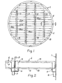
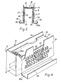
- a packed column generally designated 1 is provided with a support device 2; a packing material 90 is supported in the column 1 on top of the support device 2.
- the support device 2 includes a plurality of beams 3 extending across the column 1, which serve to reinforce structurally the support device 2, and enable the support device 2 to be secured to the column 1.
- the support device 2 also includes a circumferential sump 4 provided around the periphery thereof, and a plurality of parallel sumps 5 extending across the support device 2.
- the sumps 5 are substantially parallel to the beams 3, and each sump 5 is located in the region of a respective one of the beams 3.
- Downpipes 6 (of which only one is shown) are secured to the sump 4, and downpipes 7 (of which only one is shown) are secured to the sumps 5. Liquid can be taken from the column 1 from the downpipes 6 and 7.
- the support device 2 comprises a plate 8 having a plurality of formations 9 provided thereon; the plate 8 and formations 9 provide a corrugated configuration.
- the plate 8 is formed from a plurality of elongate members 8 a one of which is shown in cross-section in Figure 3.
- the members 8 a are juxtaposed and may be secured together by welding. It will be appreciated that the members 8 a could be manufactured in one piece.
- the formations 9 comprise spaced side walls 10 connected by an upper wall 11.
- a plurality of apertures 12 are provided in the side walls 10 to permit the flow of gas therethrough.
- a double-skin construction is provided by the formations 9 which further include cover members 13; each cover member 13 comprises spaced side walls 14 which are connected by an upper wall 15. The side walls 14 extend above the upper wall 15 to define a channel 16 therebetween; the channel 16 acts as collecting means to collect liquid flowing downwardly through the column.
- the side walls 14 of each cover member 13 are provided with apertures 17 to permit the flow of gas therethrough. The apertures 17 are disposed out of alignment with the apertures 12 in order to reduce further the flow of liquid therethrough.
- the channels 16 extend along the top of the formations 9 and deliver the liquid collected either to the circumferential sump 4 or to one of the sumps 5.
- the upper wall 15 of each cover member 13 is provided with apertures 15 a at opposite ends thereof.
- the apertures 15 a are disposed either above one of the sumps 5 or above the sump 4, so that liquid can drain into the sump from the channel 16.
- the channels 16 reduce substantially the amount of liquid which flows through the apertures 12 and 17. If the channels 16 were not provided then liquid falling on the upper wall 15 would run down the side walls 14 and a portion of this liquid may flow through the apertures 12 and 17.
- the plate 8 is provided with a base 18 and the formations 9 extend upwardly from the base 18.
- the base is non-perforated, so that neither liquid nor gas can flow therethrough.
- the base 18, together with adjacent formations 9, define a channel 19 therebetween.
- the channel 19 collects liquid not collected by the channel 16 and delivers this liquid either to the circumferential sump 4 or to one of the sumps 5.
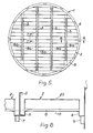
- Formations 20 are each provided with spaced side walls 21 and an upper wall 22 having a channel 23 therein.
- the channel 23 serves as collecting means and performs a similar function to the channel 16 in the embodiment shown in Figures 1 to 3.
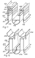
- Figure 8 shows a modification of the formations 20 shown in Figure 6.
- the formations 20 are replaced with formations 30 which comprise spaced side walls 31 and an upper wall 32.
- the side walls 31 extend above the upper wall 32 and define a channel 33 therebetween.
- the channel 33 serves as collecting means and performs a similar function to the channels 16 and 23.
- Figure 9 shows a further modification of the formations 20 shown in Figure 7.
- the formations 20 are replaced with formations 40 which comprise divergent spaced side walls 41 and an upper wall 42 having a channel 43 therein.
- the channel 43 serves as collecting means and performs a similar function to the channels 16, 23 and 33.
- the distance between the side walls 41 decreases with increasing distance form the upper wall 42. This divergence helps to prevent liquid from flowing through the apertures 12.
- FIG 10 a further embodiment of support device 1 is shown.
- the formations 20 in the embodiment of Figure 9 are the same as the formations 20 shown in Figure 6, except that they include cover members 50 which comprise spaced side walls 51 and an upper wall 52.
- a gap 53 is provided in the upper wall 52 through which liquid can flow to the channel 23.
- FIG. 11 a further embodiment of support device is designated 100.
- the support device 100 comprises a plate 101 with formations 102 and a collecting channel 103; the formations 102 comprise a double-skin construction and include cover members 104. For convenience only one cover member 104 is shown.
- First streamlining formations 105 and 106 are provided beneath upper walls 107 and 108 respectively of the formations 102.
- the streamlining formations 105 and 106 are respectively integral and non-integral with the formations 102, and are circular in shape.
- Second streamlining formations 109 are provided beneath the plate 101 between adjacent formations 102.
- the second streamlining formations 109 are integral with the formations 102.
- Figure 12 shows a chimney tray 200 comprising a plate 201 and formations 202.
- the formations 202 are provided with streamlining formations 204 and 205 to improve the gas flow.
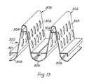
- Figure 13 shows a packing support plate 300 comprising a plate 301 and formations 302.
- the formations 302 are provided with gas flow apertures 303.
- Streamlining formations 304 and 305 are provided to improve the gas flow.
Landscapes
- Chemical & Material Sciences (AREA)
- Chemical Kinetics & Catalysis (AREA)
- Physics & Mathematics (AREA)
- Thermal Sciences (AREA)
- Organic Chemistry (AREA)
- Physical Or Chemical Processes And Apparatus (AREA)
- Gas Separation By Absorption (AREA)
- Vaporization, Distillation, Condensation, Sublimation, And Cold Traps (AREA)
Priority Applications (3)
| Application Number | Priority Date | Filing Date | Title |
|---|---|---|---|
| EP19860306550 EP0257152B1 (fr) | 1986-08-22 | 1986-08-22 | Dispositif de support pour une colonne de garnissage |
| EP19910200073 EP0425481B1 (fr) | 1986-08-22 | 1986-08-22 | Support pour une colonne garnie |
| DE19863687002 DE3687002T2 (de) | 1986-08-22 | 1986-08-22 | Tragevorrichtung fuer eine gepackte kolonne. |
Applications Claiming Priority (1)
| Application Number | Priority Date | Filing Date | Title |
|---|---|---|---|
| EP19860306550 EP0257152B1 (fr) | 1986-08-22 | 1986-08-22 | Dispositif de support pour une colonne de garnissage |
Related Child Applications (1)
| Application Number | Title | Priority Date | Filing Date |
|---|---|---|---|
| EP91200073.4 Division-Into | 1986-08-22 |
Publications (2)
| Publication Number | Publication Date |
|---|---|
| EP0257152A1 true EP0257152A1 (fr) | 1988-03-02 |
| EP0257152B1 EP0257152B1 (fr) | 1992-10-21 |
Family
ID=8196113
Family Applications (2)
| Application Number | Title | Priority Date | Filing Date |
|---|---|---|---|
| EP19910200073 Expired - Lifetime EP0425481B1 (fr) | 1986-08-22 | 1986-08-22 | Support pour une colonne garnie |
| EP19860306550 Expired EP0257152B1 (fr) | 1986-08-22 | 1986-08-22 | Dispositif de support pour une colonne de garnissage |
Family Applications Before (1)
| Application Number | Title | Priority Date | Filing Date |
|---|---|---|---|
| EP19910200073 Expired - Lifetime EP0425481B1 (fr) | 1986-08-22 | 1986-08-22 | Support pour une colonne garnie |
Country Status (2)
| Country | Link |
|---|---|
| EP (2) | EP0425481B1 (fr) |
| DE (1) | DE3687002T2 (fr) |
Cited By (5)
| Publication number | Priority date | Publication date | Assignee | Title |
|---|---|---|---|---|
| EP0517670A1 (fr) * | 1991-06-07 | 1992-12-09 | Sulzer Chemtech AG | Grille de support pour garnissage dans des colonnes d'échange de matériaux |
| WO1998041321A1 (fr) * | 1997-03-20 | 1998-09-24 | Norton Chemical Process Products Corporation | Plaque de support pour tours a emballer |
| EP2027900A3 (fr) * | 2007-08-21 | 2011-11-02 | Air Products and Chemicals, Inc. | Collecteur de liquide et redistributeur pour des colonnes conditionnées |
| CN111135699A (zh) * | 2020-03-25 | 2020-05-12 | 中建中环工程有限公司 | 一种逆流喷淋塔用托盘装置及逆流喷淋塔 |
| WO2020165073A1 (fr) * | 2019-02-14 | 2020-08-20 | Haldor Topsøe A/S | Réacteur catalytique avec poutre de support |
Families Citing this family (1)
| Publication number | Priority date | Publication date | Assignee | Title |
|---|---|---|---|---|
| FR2732616B1 (fr) * | 1995-04-04 | 1997-05-23 | Air Liquide | Distributeur de fluides |
Citations (2)
| Publication number | Priority date | Publication date | Assignee | Title |
|---|---|---|---|---|
| US3222040A (en) * | 1962-06-25 | 1965-12-07 | John S Eckert | Support plate for packed tower |
| US4171333A (en) * | 1977-05-16 | 1979-10-16 | Norton Company | Tower packing support |
Family Cites Families (2)
| Publication number | Priority date | Publication date | Assignee | Title |
|---|---|---|---|---|
| GB845369A (en) * | 1957-08-23 | 1960-08-24 | Power Gas Ltd | Improvements in or relating to grids for supporting tower packing bodies |
| GB1294926A (fr) * | 1970-01-27 | 1972-11-01 |
-
1986
- 1986-08-22 EP EP19910200073 patent/EP0425481B1/fr not_active Expired - Lifetime
- 1986-08-22 EP EP19860306550 patent/EP0257152B1/fr not_active Expired
- 1986-08-22 DE DE19863687002 patent/DE3687002T2/de not_active Expired - Fee Related
Patent Citations (2)
| Publication number | Priority date | Publication date | Assignee | Title |
|---|---|---|---|---|
| US3222040A (en) * | 1962-06-25 | 1965-12-07 | John S Eckert | Support plate for packed tower |
| US4171333A (en) * | 1977-05-16 | 1979-10-16 | Norton Company | Tower packing support |
Cited By (8)
| Publication number | Priority date | Publication date | Assignee | Title |
|---|---|---|---|---|
| EP0517670A1 (fr) * | 1991-06-07 | 1992-12-09 | Sulzer Chemtech AG | Grille de support pour garnissage dans des colonnes d'échange de matériaux |
| US5281369A (en) * | 1991-06-07 | 1994-01-25 | Sulzer Brotthers Limited | Supporting grate for packings in material exchange columns |
| WO1998041321A1 (fr) * | 1997-03-20 | 1998-09-24 | Norton Chemical Process Products Corporation | Plaque de support pour tours a emballer |
| AU714816B2 (en) * | 1997-03-20 | 2000-01-13 | Norton Chemical Process Products Corporation | Tower packing support plate |
| EP2027900A3 (fr) * | 2007-08-21 | 2011-11-02 | Air Products and Chemicals, Inc. | Collecteur de liquide et redistributeur pour des colonnes conditionnées |
| US8408026B2 (en) | 2007-08-21 | 2013-04-02 | Air Products And Chemicals, Inc. | Liquid collector and redistributor for packed columns |
| WO2020165073A1 (fr) * | 2019-02-14 | 2020-08-20 | Haldor Topsøe A/S | Réacteur catalytique avec poutre de support |
| CN111135699A (zh) * | 2020-03-25 | 2020-05-12 | 中建中环工程有限公司 | 一种逆流喷淋塔用托盘装置及逆流喷淋塔 |
Also Published As
| Publication number | Publication date |
|---|---|
| EP0425481B1 (fr) | 1993-12-15 |
| EP0425481A3 (en) | 1991-07-31 |
| DE3687002T2 (de) | 1993-04-15 |
| EP0257152B1 (fr) | 1992-10-21 |
| DE3687002D1 (de) | 1992-11-26 |
| EP0425481A2 (fr) | 1991-05-02 |
Similar Documents
| Publication | Publication Date | Title |
|---|---|---|
| US4744929A (en) | Support device for a packed column | |
| US5554329A (en) | Fractionation tray formed by triangular downcomer modules | |
| KR100327531B1 (ko) | 병류 접촉 분리 트레이 구조 및 이를 사용하는 방법 | |
| US5389343A (en) | Catalyst assembly and method for chemical process tower | |
| US5707563A (en) | V-module fractionation tray | |
| US5547617A (en) | Apparatus for increasing effective active area | |
| US4129626A (en) | Vapor-liquid contacting apparatus | |
| EP2027900B1 (fr) | Collecteur de liquide et redistributeur pour des colonnes conditionnées | |
| US5702647A (en) | Multiple downcomer high performance tray assembly | |
| US5091119A (en) | Liquid-gas contact device | |
| US5975504A (en) | Closely-spaced high capacity fractionation trays | |
| US6293528B1 (en) | Fractionation apparatus with low surface area grid above tray deck | |
| US4556522A (en) | Sieve type distillation tray with curved baffles | |
| US3013781A (en) | Fractionating apparatus | |
| EP0257152B1 (fr) | Dispositif de support pour une colonne de garnissage | |
| EP0879626A2 (fr) | Plateau de distribution de liquide | |
| US20010015504A1 (en) | Gas-liquid contacting tray | |
| US20040099970A1 (en) | Tray column with deentrainment packing below the tray | |
| US20020142130A1 (en) | Structured packing | |
| US6116583A (en) | Nestable fractionation tray antipenetration pans | |
| EP0337150B1 (fr) | Garnissage de colonne comportant un profile à rétention de fluide | |
| US5209875A (en) | Multiple-downcomer contacting tray with antipenetration devices | |
| US4318870A (en) | Distillation plate | |
| GB2325175A (en) | Heat exchanger | |
| US5948211A (en) | Distillation column downcomer having liquid permeable wall |
Legal Events
| Date | Code | Title | Description |
|---|---|---|---|
| PUAI | Public reference made under article 153(3) epc to a published international application that has entered the european phase |
Free format text: ORIGINAL CODE: 0009012 |
|
| AK | Designated contracting states |
Kind code of ref document: A1 Designated state(s): DE FR GB IT NL |
|
| 17P | Request for examination filed |
Effective date: 19880621 |
|
| 17Q | First examination report despatched |
Effective date: 19900824 |
|
| ITF | It: translation for a ep patent filed | ||
| GRAA | (expected) grant |
Free format text: ORIGINAL CODE: 0009210 |
|
| AK | Designated contracting states |
Kind code of ref document: B1 Designated state(s): DE FR GB IT NL |
|
| XX | Miscellaneous (additional remarks) |
Free format text: TEILANMELDUNG 91200073.4 EINGEREICHT AM 22/08/86. |
|
| ET | Fr: translation filed | ||
| REF | Corresponds to: |
Ref document number: 3687002 Country of ref document: DE Date of ref document: 19921126 |
|
| PGFP | Annual fee paid to national office [announced via postgrant information from national office to epo] |
Ref country code: DE Payment date: 19930713 Year of fee payment: 8 |
|
| PGFP | Annual fee paid to national office [announced via postgrant information from national office to epo] |
Ref country code: FR Payment date: 19930715 Year of fee payment: 8 |
|
| PGFP | Annual fee paid to national office [announced via postgrant information from national office to epo] |
Ref country code: GB Payment date: 19930729 Year of fee payment: 8 |
|
| PLBE | No opposition filed within time limit |
Free format text: ORIGINAL CODE: 0009261 |
|
| STAA | Information on the status of an ep patent application or granted ep patent |
Free format text: STATUS: NO OPPOSITION FILED WITHIN TIME LIMIT |
|
| PGFP | Annual fee paid to national office [announced via postgrant information from national office to epo] |
Ref country code: NL Payment date: 19930831 Year of fee payment: 8 |
|
| 26N | No opposition filed | ||
| PG25 | Lapsed in a contracting state [announced via postgrant information from national office to epo] |
Ref country code: GB Effective date: 19940822 |
|
| PG25 | Lapsed in a contracting state [announced via postgrant information from national office to epo] |
Ref country code: NL Effective date: 19950301 |
|
| NLV4 | Nl: lapsed or anulled due to non-payment of the annual fee | ||
| GBPC | Gb: european patent ceased through non-payment of renewal fee |
Effective date: 19940822 |
|
| PG25 | Lapsed in a contracting state [announced via postgrant information from national office to epo] |
Ref country code: FR Effective date: 19950428 |
|
| PG25 | Lapsed in a contracting state [announced via postgrant information from national office to epo] |
Ref country code: DE Effective date: 19950503 |
|
| REG | Reference to a national code |
Ref country code: FR Ref legal event code: ST |
|
| PG25 | Lapsed in a contracting state [announced via postgrant information from national office to epo] |
Ref country code: IT Free format text: LAPSE BECAUSE OF NON-PAYMENT OF DUE FEES;WARNING: LAPSES OF ITALIAN PATENTS WITH EFFECTIVE DATE BEFORE 2007 MAY HAVE OCCURRED AT ANY TIME BEFORE 2007. THE CORRECT EFFECTIVE DATE MAY BE DIFFERENT FROM THE ONE RECORDED. Effective date: 20050822 |