EP0257155A1 - Procédé de mise en service d'un canon perforateur et d'enregistrement des données dans un trou de forage - Google Patents
Procédé de mise en service d'un canon perforateur et d'enregistrement des données dans un trou de forage Download PDFInfo
- Publication number
- EP0257155A1 EP0257155A1 EP86306662A EP86306662A EP0257155A1 EP 0257155 A1 EP0257155 A1 EP 0257155A1 EP 86306662 A EP86306662 A EP 86306662A EP 86306662 A EP86306662 A EP 86306662A EP 0257155 A1 EP0257155 A1 EP 0257155A1
- Authority
- EP
- European Patent Office
- Prior art keywords
- recorder
- signal
- downhole
- perforating gun
- initiating
- Prior art date
- Legal status (The legal status is an assumption and is not a legal conclusion. Google has not performed a legal analysis and makes no representation as to the accuracy of the status listed.)
- Granted
Links
- 230000000977 initiatory effect Effects 0.000 title claims abstract description 26
- 238000000034 method Methods 0.000 claims abstract description 23
- 230000004044 response Effects 0.000 claims abstract description 18
- 238000010304 firing Methods 0.000 claims description 35
- 238000012360 testing method Methods 0.000 claims description 13
- 239000012530 fluid Substances 0.000 claims description 10
- 230000007246 mechanism Effects 0.000 claims description 3
- 230000003750 conditioning effect Effects 0.000 description 17
- 230000001133 acceleration Effects 0.000 description 15
- 239000002360 explosive Substances 0.000 description 14
- 238000006243 chemical reaction Methods 0.000 description 4
- 238000001514 detection method Methods 0.000 description 4
- 238000005474 detonation Methods 0.000 description 4
- 238000010586 diagram Methods 0.000 description 4
- 238000012545 processing Methods 0.000 description 4
- 241001422033 Thestylus Species 0.000 description 3
- 239000003990 capacitor Substances 0.000 description 3
- 238000012986 modification Methods 0.000 description 3
- 230000004048 modification Effects 0.000 description 3
- 238000012546 transfer Methods 0.000 description 3
- 210000001364 upper extremity Anatomy 0.000 description 3
- 230000015572 biosynthetic process Effects 0.000 description 2
- 238000013500 data storage Methods 0.000 description 2
- 230000003111 delayed effect Effects 0.000 description 2
- 238000004880 explosion Methods 0.000 description 2
- 230000014509 gene expression Effects 0.000 description 2
- 230000033001 locomotion Effects 0.000 description 2
- 210000003141 lower extremity Anatomy 0.000 description 2
- 230000002238 attenuated effect Effects 0.000 description 1
- 230000008901 benefit Effects 0.000 description 1
- 238000004891 communication Methods 0.000 description 1
- 239000004020 conductor Substances 0.000 description 1
- 230000008602 contraction Effects 0.000 description 1
- 230000000994 depressogenic effect Effects 0.000 description 1
- 238000013461 design Methods 0.000 description 1
- 230000000694 effects Effects 0.000 description 1
- 230000004907 flux Effects 0.000 description 1
- 238000004519 manufacturing process Methods 0.000 description 1
- 238000005259 measurement Methods 0.000 description 1
- 230000005055 memory storage Effects 0.000 description 1
- 239000013641 positive control Substances 0.000 description 1
- 230000008569 process Effects 0.000 description 1
- 230000000630 rising effect Effects 0.000 description 1
- 230000011664 signaling Effects 0.000 description 1
- 239000007787 solid Substances 0.000 description 1
- 230000001360 synchronised effect Effects 0.000 description 1
- 230000000007 visual effect Effects 0.000 description 1
- 238000011179 visual inspection Methods 0.000 description 1
Images


Classifications
-
- E—FIXED CONSTRUCTIONS
- E21—EARTH OR ROCK DRILLING; MINING
- E21B—EARTH OR ROCK DRILLING; OBTAINING OIL, GAS, WATER, SOLUBLE OR MELTABLE MATERIALS OR A SLURRY OF MINERALS FROM WELLS
- E21B47/00—Survey of boreholes or wells
- E21B47/06—Measuring temperature or pressure
-
- E—FIXED CONSTRUCTIONS
- E21—EARTH OR ROCK DRILLING; MINING
- E21B—EARTH OR ROCK DRILLING; OBTAINING OIL, GAS, WATER, SOLUBLE OR MELTABLE MATERIALS OR A SLURRY OF MINERALS FROM WELLS
- E21B43/00—Methods or apparatus for obtaining oil, gas, water, soluble or meltable materials or a slurry of minerals from wells
- E21B43/11—Perforators; Permeators
- E21B43/116—Gun or shaped-charge perforators
- E21B43/1185—Ignition systems
- E21B43/11857—Ignition systems firing indication systems
-
- E—FIXED CONSTRUCTIONS
- E21—EARTH OR ROCK DRILLING; MINING
- E21B—EARTH OR ROCK DRILLING; OBTAINING OIL, GAS, WATER, SOLUBLE OR MELTABLE MATERIALS OR A SLURRY OF MINERALS FROM WELLS
- E21B47/00—Survey of boreholes or wells
- E21B47/26—Storing data down-hole, e.g. in a memory or on a record carrier
Definitions
- the present invention relates to downhole recorders for use in oil and gas wells.
- Electronic recorders provide the advantage of small size and are capable of providing the data directly in digital form to data processing instrumentation. However, electronic recorders generally have more limited storage capacity than do mechanical recorders.
- U.S. Patent No. 4,033,186 shows a downhole electronic recorder wherein a preprogrammed solid state clock initiates measurement sequences and deactivates the circuitry between sequences. A time delay is programmed into the clock so that the first reading sequence is not initiated until the gauge has been inserted into the well shaft to a desired depth.
- the wall of the borehole is perforated, for example, to test the producing capability of a formation, or to bring a well into production.
- the wall is perforated typically with the use of a perforating gun which is either suspended in the well on a wireline or is run into the well on tubing.
- a perforating gun which is either suspended in the well on a wireline or is run into the well on tubing.
- considerable time and expense are required to run in the guns, and it is desireable to reliably determine that the perforating guns have been successfully actuated.
- a sensor the gun can be coupled to surface equipment by wire line in order to detect and convey signals indicative of gun firing.
- Such techniques utilize, for example: (1) an inertial switch disposed within the perforating gun and arranged to interrupt the electrical gun firing circuit in response to gun recoil from firing; (2) an accelerometer disposed within the perforating gun and arranged to generate an electrical signal in response to recoil motion of the perforating gun; and (3) a downhole microphone (geophone) arranged to convey the sound of the perforating gun to a speaker at the surface.
- an explosive device is attached to one end of a perforating gun which is actuated from an opposing end.
- the explosive device implements a time delay so that complete detonation of the perforating gun is followed in time by several seconds by the actuation of the explosive device.
- a sensor at the wellhead detects energy produced by the firing of the perforating gun and, subsequently, energy from the firing of the explosive device, so that can be reliably determined at the wellhead whether the gun has fired completely.
- This signalling technique works quite well under most circumstances. However, in environments where a great deal of background noise is present, for example, on a floating rig, the surface noise tends to obscure the signals from the perforating gun and the explosive device.
- a method for recording data downhole in a borehole.
- a recorder having a data memory is lowered into a data recording position in the borehole.
- a signal is transmitted downhole into the borehole and the recorder is initiated to begin recording data at an ascertainable memory location of the data memory in response to a downhole stimulus produced in response to the transmitted signal.
- the recorder can be maintained in a low power consumption mode of operation until it is actually desired to record data. Positive control over the initiation of recording is afforded and the most efficient use of memory capacity is achieved. Accordingly, in many applications, relatively compact and inexpensive electronic memory devices can be utilized in place of larger and mechanically intricate conventional recorders.
- the method of the present invention also permits the efficient utilization of mechanical recording devices by conserving memory space for the storage of useful data and facilitates data utilization by commencing data recording at an ascertainable memory location.
- a method for detecting the firing of an explosive device downhole in a borehole.
- the method includes lowering a recorder means into the borehole; transmitting a stimulus downhole for firing the explosive device; retrieving the recorder means from the borehole; and analyzing data recorded downhole by the recorder means to detect evidence of the firing of the explosive device.
- the method of the present invention is especially useful in detecting the actuation of a perforating gun, where the recorder means is positioned in close proximity to the gun. The recorder is thus enabled to receive and record relatively unattenuated signals emitted by the perforating gun when it fires, to reliably record the event.
- a system for use in detecting the firing of an explosive device downhole in a borehole.
- a downhole recorder means is provided for recording a signal produced by the firing of the explosive device. Since the recorder means is downhole, energy produced from the firing of the explosive device is not appreciably attenuated when it reaches the recorder means resulting in a higher signal to noise ratio, making detection of the firing of the explosive device more likely.
- the system further includes means for providing an output based on the recorded signal to an operator at the surface.
- a downhole recorder for recording the firing of a perforating gun downhole in a borehole.
- the recorder comprises signal storage means for recording signals produced by the firing of the perforating gun.
- the signal storage means is actuable upon receipt of an actuation signal thereby.
- the recorder further comprises means for producing the actuation signal upon receipt of a stimulus indicating the firing of the perforating gun. Accordingly, it becomes possible to utilize electronic storage devices having limited memory capability for this purpose, since data only is stored upon the actuation of the perforating gun. In this manner, it is also possible to conserve batteries used to energize the circuitry of the recorder until such time as useful data is available for recording.
- a system for testing an oil or gas well.
- the system comprises a perforating gun; downhole recorder means for storing test data; and means for actuating the downhole recorder means to commence storing test data therein in response to a signal indicating the firing of the perforating gun. Since it takes a considerable amount of time to run in a test string on a drill pipe, for example in performing a drill stem test, it is desireable to commence the recording of test data only after the drill string has been lowered to the desired depth and the perforating gun actuated. This avoids recording unnecessary data so that memory capacity is best utilized, and permits battery energy to be preserved.
- a system for recording data downhole in a borehole.
- the system comprises a recorder means positioned downhole in the borehole; means for initiating the recording of data at an ascertainable memory location of the recorder means in response to a downhole stimulus produced in response to a transmitted signal; and means for transmitting the signal from the surface of the borehole downhole to the initiating means.
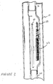
- a casing 10 lines a borehole in the earth.
- a tubing string 12 has been run into the borehole to position a string of perforating guns 14 suspended from the tubing string 12 opposite a portion 16 of the casing which it is desired to perforate.
- the purpose of forming the perforations may be, for example, to test the productive capabilities of a formation separated from the interior of the borehole by the casing portion 16, or to carry out a permanent completion of the well.
- a firing head 18 is threadedly coupled to an upper extremity of perforating guns 14.
- the firing head 18 may be, for example, a mechanical firing head which is actuated by the impact of a detonating bar dropped through the tubing 12 to impact the firing head, or a pressure actuated firing head.
- a vent assembly 20 is threadedly coupled to the firing head 18 at an upper extremity thereof and provides a means of communicating fluids to the interior of the tubing string 12 from the lower portion of the borehole.
- a packer 22 separates the lower portion of the borehole in which the perforating guns 14 are suspended from an upper borehole annulus.
- a shot detection delay device 24 is threadedly coupled to a lower extremity of the perforating guns 14.
- the delay device 24 is arranged so that a detonating cord extending the entire length of the guns 14 will initiate a time delayed explosion within the delay device 24 provided the detonating cord detonates its entire length.
- the time delayed explosion within the delay device 24 occurs, for example, ten seconds after the detonation of the perforating guns 14 to produce a distinct signal which indicates that the perforating guns 14 have detonated their entire length.
- the delay device 24 is described in greater detail in co-pending U.S. patent application serial #505,911 filed June 20, 1983, in the names of Edward A. Colle, Jr. et al. and entitled METHOD AND APPARATUS FOR DETECTING FIRING OF PERFORATING GUN.
- a downhole recorder 26 is positioned in the side pocket of a side pocket mandrel 28 threadedly coupled at its lower extremity to the vent assembly 20 and at its upper extremity to a joint of the tubing string 12.
- the recorder 26 stores signals which bear a predetermined relationship to accelerations experienced by the recorder 26 due to the detonation of the perforating guns 14 and the subsequent actuation of the delay device 24. Due to the relatively close positioning of the downhole recorder 26 with respect to the perforating guns 14 and the delay device 24, the recorder 26 receives relatively strong accelerations from the actuation of these devices and, therefore, the accelerations are readily distinguishable from background noise.
- the recorder 26 can be run in with the tubing string, or later lowered through the tubing string and landed in the side pocket with the use of conventional tools and techniques.
- a detonating bar 30 (see Figure 2) is dropped through the tubing string 12 so that it impacts the firing head 18 to detonate the guns 14. It will be appreciated that the placement of the recorder 26 in the side pocket mandrel permits the detonating bar 30 to pass therethrough unobstructed.
- the very strong accelerations experienced by the tubing string and the side pocket mandrel therein as a result of the actuation of the guns 14 triggers the recording mode of the recorder 26 which thereupon records accelerations for a short period of time, for example, 40 seconds.
- the shot detection delay device 24 will be activated if the perforating guns 14 have detonated their entire length, and the resultant acceleration of the tubing string will be recorded by the recorder 26. Thereafter, the recorder 26 is retrieved from the side pocket mandrel to the surface by means of a fishing tool which latches onto a fishing neck 32 of the recorder 26. Thereupon, the data stored in the recorder 26 is transferred to a surface unit (described in greater detail below) which then is capable of providing the same data in digital format for data processing purposes, and also in analog format which can be displayed, for example, for analysis on a strip chart. While the use of the delay device 24 is often helpful in detecting gun firing, its use is not essential in the practice of the present invention.
- the block diagram of Figure 3 illustrates the circuitry of the recorder 26.
- the circuitry is protected by a pressure-tight housing of the recorder which also encloses a battery supply (not shown) for the circuitry.
- An accelerometer 40 is operative to continuously provide an electrical signal on its output 42, the signal being proportional to the accelerations experienced by the accelerometer 40 within the recorder 26.
- the output 42 of the accelerometer 40 is coupled to the input of signal conditioning circuit 44.
- the electrical signal provided by the accelerometer 40 at its output has a relatively low amplitude; accordingly, the signal conditioning circuit 44 has an input amplifier which boosts the amplitude of the signal provided on the output 44.
- the amplified signal is then rectified by a precision rectifier of the signal conditioning circuit 44 which then provides the thus - rectified signal to an output 46.
- the signal thus provided at output 46 is a single polarity signal proportional in amplitude to accelerations experienced by the recorder.
- the signal provided at output 46 is used both as an input to the recorder's memory for storing acceleration data, and also is used to determine when the guns have fired, so that data is then recorded until the memory has been filled.
- the circuitry which serves to control the storage of data is first discussed below.
- a threshold comparator 50 has an input coupled with the output 46 of the signal conditioning circuit 44. An input of the threshold comparator 50 is coupled to a voltage divider 52 which provides a reference voltage V ref1 . Threshold comparator 50 provides a low level on an output 54 thereof until it receives a signal from the output 46 of the signal conditioning circuit 44 which exceeds Vref1 in amplitude, whereupon a high voltage level, or logic 1, is provided by the comparator 50 to its output 54.
- the reference voltage V ref1 is equal in magnitude to the voltage which appears on output 46 when the accelerometer 40 experiences an acceleration of 500 g's. It is in this manner that the circuit of Figure 3 detects that the guns have been fired, since the accelerometer will thereupon experience an acceleration in excess of 500 g's, while it is most unlikely that the accelerometer will experience such an acceleration beforehand.
- a first D-type flip-flop circuit 60 has its D input held at a high voltage level V+ and its clock input coupled to the output 54 of the threshold comparator 50.
- the reset terminal Rst of flip-flop 60 is connected to the output of an inverter 62.
- the input of inverter 62 is connected to the junction of a resistor 64 and a capacitor 68.
- the second terminal of resistor 64 is connected to V+, while the second terminal of the capacitor 68 is connected to ground. Accordingly, when power is first applied to the circuit of Figure 3, a low level voltage will be supplied to the input of the inverter 62, such that a high voltage level is initially provided to the reset terminal of flip-flop 60.
- Flip-flop 60 is, therefore, initially reset.
- a second D-type flip-flop 70 has its D input coupled to the voltage level V + and its reset terminal Rst connected to the output of inverter 62. Accordingly, like flip-flop 60, flip-flop 70 will be reset initially when power is supplied to the circuit of Figure 3.
- the clock terminal of flip-flop 70 is connected to an output E oM of a memory circuit 74. The voltage level on the output E QM is initially low.
- a first input of a two input NAND gate 76 is coupled to the Q terminal of the flip-flop 60 and a second input to the NAND gate 76 is coupled to the 0 terminal of the flip-flop 70. Since flip-flop 60 is initially reset, the output of NAND gate 76 initially is high.
- NAND gate 76 is coupled to one input of a two input NAND gate 80.
- a second input of NAND gate 80 is coupled through a resistor 82 to the positive voltage level V+.
- an external reset line E R Also coupled to the second input of NAND gate 80 is an external reset line E R whose purpose will be explained below in connection with the circuit of Figure 4. Since both inputs of NAND gate 80 are initially high, the output thereof is initially low.
- the input of an inverter 84 is coupled to the output of NAND gate 80.
- the output of the inverter 84 is a Reset line coupled to a reset input Rst of memory circuit 74 and also to a reset input Rst of a clock circuit 88.
- the voltage level on the reset line will be initially high due to the initially low voltage level at the output of NAND gate 80.
- the high level on the reset line serves to disable the clock circuit 88 from producing clock pulses and also resets a memory address counter of memory circuit 74. At this point the recorder is operating in a standby mode.
- the clock circuit 88 When the reset line is brought low, as explained below, the clock circuit 88 will begin producing a first clock pulse on a Sync output which is coupled to the address counter of memory circuit 74.
- a low level on the reset line also enables the address counter of memory circuit 74 to begin accumulating a count under the control of the signal from the clock circuit 88. Since the memory address counter is reset just before data storage begins, the first byte of data is stored at an ascertainable location in memory. Each subsequently received byte is stored in a sequential- lyaddressed location as the counter is incremented.
- An analog-to-digital converter circuit A/D 100 has a data input coupled to the output terminal 46 of signal conditioning circuit 44 to receive the amplified and rectified signal from the accelerometer 40.
- a second input of A/D 100 is connected to a reference voltage source Vrf2 to serve as a reference in performing its analog to digital conversion of the signal received from the output 46.
- Digitized versions of the accelerometer signal from output 46 are provided by A/D 100 to an 8 bit data bus coupled to the data terminals of the memory circuit 74.
- the data bus is also coupled to an output plug for transferring data to the surface unit, as explained below.
- Intemal control over the analog to digital conversion and memory storage process is maintained by a second clock signal produced by the clock circuit 88 on an output terminal 102 thereof.
- This signal is coupled both to memory circuit 74 and to a first input of a two input NAND gate 104.
- the output of NAND gate 104 is connected to a start conversion terminal S C of A/D 100.
- Read/write control is achieved through an external input terminal R /W coupled both to a first terminal of a resistor 106 and the input terminal of an inverter 108.
- a second terminal of the resistor 106 is connected to the positive voltage source V+.
- the output of inverter 108 is coupled both to the first of a pair of read/write control lines of memory circuit 74 and to the input terminal of a further inverter 110.
- the output of inverter 110 is coupled to the second of the two read/write control lines of memory 74 and also to the second input of NAND gate 104.
- the circuit of Figure 3 When the circuit of Figure 3 is not coupled to the surface unit of Figure 4, for example, while the recorder is downhole and recording data, it is in the write mode.
- the R /W terminal In the write mode, the R /W terminal is tied through resistor 106 to V+ so that the input to the inverter 108 is high. Consequently, the first and second read/write control lines of the memory circuit 74 are respectively at low and high voltage levels, while the second input to NAND gate 104 is high. This places the memory circuit 74 in the write mode so that data received on the data bus from A/D 100 can be stored in memory at the sequential addresses determined by incrementing the memory counter of the circuit 74 after the Reset line has been brought low.
- the clock signal on the terminal 102 is brought high by the clock circuit 88 to generate a low voltage at the SC terminal of AID 100, so that the present analog voltage from the output 46 of the signal conditioning circuit 44 is digitized by A/D 100. Then the voltage level on terminal 102 is brought low by the clock circuit 88 after sufficient time has passed to complete the analog to digital conversion, so that the memory circuit 74 is enabled to store the digitized signal provided on the data bus by the analog to digital converter 100.
- the circuitry of the surface unit here illustrated includes a memory circuit 120 structurally identical to memory circuit 74 of Figure 3.
- the circuit of Figure 4 also includes a clock circuit 124 providing the necessary clock signals to memory circuit 120 over lines 126 and 128.
- the data bus of the memory circuit 120 is coupled with the data bus of a digital-to-analog converter D/A 130 having a single analog output terminal ⁇ out .
- the data bus is also available to exterior circuitry through a plug connection shown as 132.
- the operation of D/A 130 is synchronized with that of the memory circuit 120 by virtue of clock signals provided to D/A 130 from clock circuit 124 over line 134.
- Read/write control of the surface unit is achieved externally over input R /W.
- input R /W is tied to ground through a resistor 136.
- the terminal R /W is also connected to the input of an inverter 140 whose output is connected (1) to a first read/write control line of memory circuit 120 and (2) to the input of an inverter 142.
- the output of inverter 142 is coupled to a second read/write input of memory 120.
- the first read/write input to memory 120 has a high voltage level
- the second input has a low voltage level, which corresponds with the read mode of memory circuit 120.
- a further inverter 144 has an input coupled through a resistor 146 to ground and also to a plug terminal which is coupled to the Reset line of the circuit of Figure 3 when it is plugged into the surface unit of Figure 4.
- the output of inverter 144 is connected to the first input of a two input NAND gate 150.
- the second input of NAND gate 150 is connected with the Q terminal of a D type flip-flop 152.
- the D terminal of flip-flop 152 is coupled both to a positive voltage level V + and also to the first terminal of a resistor 154.
- a second terminal of resistor 154 is coupled to ground.
- the reset terminal Rst of flip-flop 152 is coupled to the first terminal of a resistor 156 whose second terminal is also coupled to ground.
- a first terminal of an SPST momentary contact switch 158 is also coupled to the reset terminal of flip-flop 152.
- the second terminal of switch 158 is connected to V+.
- the clock terminal of flip-flop 152 is connected to the Eom terminal of memory circuit 120.
- the Q terminal of flip-flop 152 is connected to a plug terminal which in turn is coupled to the external reset E R terminal of the circuit of Figure 3 when the surface unit is connected thereto.
- the output of NAND gate 150 is connected (1) to the reset terminal Rst of memory circuit 120, and (2) to a first reset terminal Rst of clock circuit 124, and (3) to a first terminal of a resistor 160.
- the second terminal of resistor 160 is connected to the base terminal of an NPN transistor 162, whose emitter is coupled to ground.
- the collector of tran- sister 162 is connected to the first terminal of a resistor 164 whose second terminal is connected to the cathode of a light emitting diode LED 166.
- the anode of LED 166 is connected to V+.
- a second reset terminal Rst of clock 124 is connected to a first terminal of a resistor 170 whose second terminal is coupled to ground.
- the second reset terminal of clock circuit 124 is also coupled to a plug terminal which is connected to the Sync line of the Figure 3 circuit when it is plugged to the surface unit.
- the surface unit is turned on before the recorder is connected thereto. Then the momentary contact switch 158 is temporarily depressed to reset flip-flop 152. Accordingly, there is a high level on the Q terminal of flip-flop 152 and also at the output of inverter 144. At the same time, the output of NAND gate 150 is low which enables the memory counter of memory circuit 120. Since both reset terminals of clock 124 are low, clock 124 is enabled to produce clock pulses so that the memory counter of memory circuit 120 gradually accumulates a count. When the memory circuit 120 has cycled through completely, line E oM goes high clocking a low level into the Q terminal of flip-flop 152. This brings the output of NAND gate 150 high so that clock circuit 124 is reset together with the memory counter of memory circuit 120. At this point the recorder which has been retrieved from the borehole may be connected to the surface unit to transfer data thereto.
- connecting the downhole recorder to the surface unit connects the Sync terminal of the recorder to the Sync terminal of the surface unit, the Reset line of the recorder to the Reset terminal of the surface unit, the external Reset line E R to the corresponding terminal of the surface unit, and the data bus of the recorder to that of the surface unit.
- the recorder applies a high voltage level to the R /W terminal of the surface unit, so that the memory 120 is now in the write mode.
- Connecting the surface unit to the recorder also ties the R /W terminal of the recorder to ground through the surface unit, so that the recorder is presently in the read mode.
- the flip-flop 152 of the surface unit Since the flip-flop 152 of the surface unit is presently set, its Q terminal is at a high voltage level which maintains the previously reset condition of the recorder. To initiate data transfer, the switch 158 is temporarily closed to reset flip-flop 152. This brings the Q terminal of flip-flop 152 low, so that the Reset line of the recorder ( Figure 3) is now low. Since the Reset line of the recorder is now low, the output of inverter 144 in Figure 4 is now high, and since flip-flop 152 has been reset, its Q terminal also is high. Accordingly, the reset line coupled to the output of NAND gate 150 is now brought low, so that clock circuit 124 and the memory counter of memory circuit 120 are enabled.
- the clock of the recorder is also enabled so that it begins to produce clock pulses for incrementing the memory counter of memory circuit 74 ( Figure 3). Since the Sync line from clock circuit 88 is connected to the second reset terminal of clock circuit 124, clock circuit 124 is constrained to count in synchrony with clock circuit 88, so that the address accumulated in memory circuit 74 corresponds to that accumulated in memory circuit 120 as data is transferred.
- line E oM of Figure 3 When the entire contents of memory circuit 74 have been read out, line E oM of Figure 3 is brought high, clocking a low level into the Q terminal of flip-flop 70. Since the counter of memory circuit 120 of Figure 4 has also reached its maximum count, its line E om is also brought high at the same time clocking a high level into the Q terminal of flip-flop 152. Since the extemal reset E R line is now high and the output of NAND gate 76 of Figure 3 is also high, the Reset line of the recorder is likewise high, disabling clock circuit 88 and the memory address counter.
- inverter 144 of Figure 4 will be low (along with the Q terminal of flip-flop 152) which has just been clocked low by the rising edge of E OM ), so that the address counter of memory circuit 120 and clock circuit 124 of Figure 4 also are reset.
- the recorder may now be disconnected from the surface unit, as the contents of its memory have been transferred to that of the surface unit.
- the data contained in the memory circuit of the surface unit may be transferred in digital form to permanent storage (for example, on tape) for further processing, and it can also be recorded in analog form (for example, on a strip chart) through the A ou r terminal of D/A 130. Visual inspection of the strip chart record will reveal whether guns 14 have fired.
- the present invention is also applicable to the recording of test data, for example, pressure data, temperature data, etc.
- a recorder circuit for use in recording pressure data is shown in block form. Elements of Figure 5A corresponding to those of Figure 3 bear the same reference numerals.
- a pressure transducer 200 is exposed to fluid pressure on the exterior of the recorder and generates a signal bearing a known relationship with such fluid pressure.
- An output terminal 202 of pressure transducer 200 is coupled to an input terminal of signal conditioning circuit 204.
- Signal conditioning circuit 204 amplifies the signal from the pressure transducer 200 and provides such amplified signal as a single polarity signal on an output terminal 206.
- Output terminal 206 is connected both to the input of threshold comparator 50 and to the input of analog-to-digital convertor AID 100.
- Pressure transducer 200 thereupon produces an output signal of relatively large magnitude which is sufficient to cause threshold comparator 50 to output a high voltage level, such that the record mode of the memory is initiated.
- the output of the signal conditioning circuit is provided to the input of the analog-to-digital converter AID 100 to be digitized for storage in the memory circuit 74.
- the clock circuit 88 can be adjusted to produce clock pulses of relatively low frequency so that the memory 74 is enabled to record pressure data over a correspondingly longer period of time than that provided in the case of the circuit of Figure 3.
- the circuit of Figure 5A may be utilized for shot detection, in which case the clock frequency is accordingly adjusted.
- a transducer 220 is used to produce data to be recorded in the memory of the circuit.
- transducer 220 may be a thermocouple which serves to produce a signal bearing a known relationship with downhole temperature.
- the output signal from the transducer 220 is provided to an input of a signal conditioning circuit 222 having an output of 224 connected to the data input of analog-to-digital converter A/D 100.
- Signal conditioning circuit 222 serves to amplify the signal from transducer 220 and provides a signal polarity version thereof on its output line 224.
- a second transducer 210 has an output 212 coupled to the input of a signal conditioning circuit 214.
- Signal conditioning circuit 214 has an output 216 coupled to the input of threshold comparator 50.
- transducer 210 produces an electrical pulse in response to changes in magnetic flux. In this manner, transducer 210 produces one or more pulses as the detonating bar 30 drops past the recorder 26, as shown in Figure 2. These pulses are amplified and rectified by signal conditioning circuit 214 and serve to stimulate threshold comparator 50 to output a logic 1 on line 54. Accordingly, the record mode is thus initiated just prior to impact of the detonating bar with the firing head.
- acccelerometer 40 and signal conditioning circuit 44 are substituted for transducer 210 and signal conditioning circuit 214.
- the transducer 210 is replaced by a pressure transducer in communication with fluid pressure in the borehole annulus above the packer 22. This could be achieved, for example, by placing the side pocket mandrel, or other carrier for the recorder, above the packer and introducing upper borehole annulus fluid pressure to the pressure transducer through an aperture in the wall of the side pocket mandrel or other carrier for the recorder.
- the recorder 26 enclosing the circuit of Figure 3 is hard mounted to a pup joint arranged beneath the perforating guns. Upon gun actuation, the recorder stores acceleration data indicating the magnitude of forces generated by the guns downhole, which is useful in the design of downhole tools to operate in conjunction with perforating guns.
- the recorder is mounted in a gauge carrier and encases the circuit of Figure 5A for measuring pressure downhole, or else encases the circuit of Figure 5B for measuring downhole temperature.
- a mechanical pressure recorder utilizes a Bourdon tube to transduce pressure to the fluctuation of a stylus.
- the stylus scribes an analog record of pressure over time on a plate moved past the stylus by a clock mechanism. Movement of the plate past the stylus is initiated upon the receipt of a signal indicating the firing of a perforating gun. For example, a large acceleration of the recorder experienced as a result of gun firing enables the clock mechanism to advance the plate.
- Pressure signals and other forms of signals originating from or produced in response to signals originating from the wellhead can also be utilized for this purpose.
Landscapes
- Life Sciences & Earth Sciences (AREA)
- Engineering & Computer Science (AREA)
- Geology (AREA)
- Mining & Mineral Resources (AREA)
- Physics & Mathematics (AREA)
- Environmental & Geological Engineering (AREA)
- Fluid Mechanics (AREA)
- General Life Sciences & Earth Sciences (AREA)
- Geochemistry & Mineralogy (AREA)
- Geophysics (AREA)
- Recording Measured Values (AREA)
- Geophysics And Detection Of Objects (AREA)
Priority Applications (2)
| Application Number | Priority Date | Filing Date | Title |
|---|---|---|---|
| DE8686306662T DE3677219D1 (de) | 1986-08-28 | 1986-08-28 | Verfahren zur betaetigung einer schiessvorrichtung und zur aufnahme von daten in einem bohrloch. |
| AT86306662T ATE60402T1 (de) | 1986-08-28 | 1986-08-28 | Verfahren zur betaetigung einer schiessvorrichtung und zur aufnahme von daten in einem bohrloch. |
Applications Claiming Priority (1)
| Application Number | Priority Date | Filing Date | Title |
|---|---|---|---|
| US06/741,074 US4660638A (en) | 1985-06-04 | 1985-06-04 | Downhole recorder for use in wells |
Publications (2)
| Publication Number | Publication Date |
|---|---|
| EP0257155A1 true EP0257155A1 (fr) | 1988-03-02 |
| EP0257155B1 EP0257155B1 (fr) | 1991-01-23 |
Family
ID=24979269
Family Applications (1)
| Application Number | Title | Priority Date | Filing Date |
|---|---|---|---|
| EP86306662A Expired - Lifetime EP0257155B1 (fr) | 1985-06-04 | 1986-08-28 | Procédé de mise en service d'un canon perforateur et d'enregistrement des données dans un trou de forage |
Country Status (4)
| Country | Link |
|---|---|
| US (1) | US4660638A (fr) |
| EP (1) | EP0257155B1 (fr) |
| AU (1) | AU594360B2 (fr) |
| CA (1) | CA1254500A (fr) |
Cited By (1)
| Publication number | Priority date | Publication date | Assignee | Title |
|---|---|---|---|---|
| GB2406871A (en) * | 2002-12-03 | 2005-04-13 | Schlumberger Holdings | Intelligent well perforation system |
Families Citing this family (31)
| Publication number | Priority date | Publication date | Assignee | Title |
|---|---|---|---|---|
| US4846269A (en) * | 1984-09-24 | 1989-07-11 | Otis Engineering Corporation | Apparatus for monitoring a parameter in a well |
| US5130705A (en) * | 1990-12-24 | 1992-07-14 | Petroleum Reservoir Data, Inc. | Downhole well data recorder and method |
| US5327971A (en) * | 1992-10-19 | 1994-07-12 | Marathon Oil Company | Pressure recorder carrier and method of use |
| US5293937A (en) * | 1992-11-13 | 1994-03-15 | Halliburton Company | Acoustic system and method for performing operations in a well |
| US5353873A (en) * | 1993-07-09 | 1994-10-11 | Cooke Jr Claude E | Apparatus for determining mechanical integrity of wells |
| US5925825A (en) * | 1994-10-05 | 1999-07-20 | Franklin Electric Co., Inc. | Clamp and cup securing strain gauge cell adjacent pressure transmitting diaphragm |
| US5863185A (en) * | 1994-10-05 | 1999-01-26 | Franklin Electric Co. | Liquid pumping system with cooled control module |
| US5579842A (en) * | 1995-03-17 | 1996-12-03 | Baker Hughes Integ. | Bottomhole data acquisition system for fracture/packing mechanisms |
| US6464004B1 (en) * | 1997-05-09 | 2002-10-15 | Mark S. Crawford | Retrievable well monitor/controller system |
| US6105688A (en) * | 1998-07-22 | 2000-08-22 | Schlumberger Technology Corporation | Safety method and apparatus for a perforating gun |
| US6179064B1 (en) * | 1998-07-22 | 2001-01-30 | Schlumberger Technology Corporation | System for indicating the firing of a perforating gun |
| US6443228B1 (en) * | 1999-05-28 | 2002-09-03 | Baker Hughes Incorporated | Method of utilizing flowable devices in wellbores |
| FR2808836B1 (fr) * | 2000-05-12 | 2002-09-06 | Gaz De France | Procede et dispositif de mesure de parametres physiques dans un puits d'exploitation d'un gisement ou d'une reserve souterraine de stockage de fluide |
| WO2002006716A1 (fr) * | 2000-07-19 | 2002-01-24 | Novatek Engineering Inc. | Systeme de transmission de donnees pour colonne d'organes de forage de fond de trou |
| US6564866B2 (en) * | 2000-12-27 | 2003-05-20 | Baker Hughes Incorporated | Method and apparatus for a tubing conveyed perforating guns fire identification system using enhanced marker material |
| EP1476638A4 (fr) * | 2002-02-01 | 2010-06-23 | Geox Systems Ltd | Procede permettant de determiner l'ampleur d'une detonation au moyen de l'energie sismique |
| US7090010B1 (en) | 2003-09-25 | 2006-08-15 | Todd Martin | Gauge carrier sub apparatus |
| US20070167051A1 (en) * | 2004-11-10 | 2007-07-19 | Reynolds Harris A Jr | Data communications embedded in threaded connections |
| US7802619B2 (en) * | 2008-09-03 | 2010-09-28 | Probe Technology Services, Inc. | Firing trigger apparatus and method for downhole tools |
| WO2013166602A1 (fr) | 2012-05-07 | 2013-11-14 | Packers Plus Energy Services Inc. | Procédé et système de surveillance d'opérations de forage |
| US9291040B1 (en) | 2015-02-20 | 2016-03-22 | Geodynamics, Inc. | Select fire switch form factor system and method |
| US9938789B2 (en) | 2015-04-23 | 2018-04-10 | Baker Hughes, A Ge Company, Llc | Motion activated ball dropping tool |
| WO2018022200A1 (fr) * | 2016-07-27 | 2018-02-01 | Geodynamics, Inc. | Système et procédé de commande de commutation de tir sélectif |
| US10161733B2 (en) | 2017-04-18 | 2018-12-25 | Dynaenergetics Gmbh & Co. Kg | Pressure bulkhead structure with integrated selective electronic switch circuitry, pressure-isolating enclosure containing such selective electronic switch circuitry, and methods of making such |
| US10725202B2 (en) * | 2017-07-21 | 2020-07-28 | Baker Hughes, A Ge Company, Llc | Downhole electronics package having integrated components formed by layer deposition |
| US10598002B2 (en) | 2017-09-05 | 2020-03-24 | IdeasCo LLC | Safety interlock and triggering system and method |
| NO20210574A1 (en) * | 2018-12-07 | 2021-05-07 | Halliburton Energy Services Inc | Using a downhole accelerometer to monitor vibration |
| US11885215B2 (en) | 2021-01-14 | 2024-01-30 | Halliburton Energy Services, Inc. | Downhole pressure/temperature monitoring of ESP intake pressure and discharge temperature |
| US12460535B2 (en) | 2022-04-01 | 2025-11-04 | Halliburton Energy Services, Inc. | Downhole pressure/temperature monitoring of ESP intake pressure and discharge temperature with a gauge sensor employing an offset centerline |
| US12104473B2 (en) | 2022-04-01 | 2024-10-01 | Halliburton Energy Services, Inc. | Downhole pressure/temperature monitoring of ESP intake pressure and discharge temperature with a gauge mandrel employing an offset centerline |
| US12359896B2 (en) | 2022-07-29 | 2025-07-15 | DynaEnergetics Europe GmbH | Detonator including a multidimensional circuit board |
Citations (6)
| Publication number | Priority date | Publication date | Assignee | Title |
|---|---|---|---|---|
| US4033186A (en) * | 1976-08-06 | 1977-07-05 | Don Bresie | Method and apparatus for down hole pressure and temperature measurement |
| GB2093501A (en) * | 1981-02-23 | 1982-09-02 | Vann Roy Randell | Method of Firing Perforating Gun and Simultaneously Recording Downhole Pressure |
| US4478294A (en) * | 1983-01-20 | 1984-10-23 | Halliburton Company | Positive fire indicator system |
| EP0129350A2 (fr) * | 1983-06-20 | 1984-12-27 | Geo Vann, Inc. | Procédé et dispositif de détection de la mise à feu d'un canon perforateur de puits |
| US4531590A (en) * | 1984-03-26 | 1985-07-30 | Baker Oil Tools, Inc. | Fluid pressure actuated perforating gun |
| GB2164684A (en) * | 1984-09-24 | 1986-03-26 | Otis Eng Co | Apparatus for monitoring a parameter in a well |
Family Cites Families (7)
| Publication number | Priority date | Publication date | Assignee | Title |
|---|---|---|---|---|
| US4006777A (en) * | 1976-02-06 | 1977-02-08 | Labauve Leo C | Free floating carrier for deep well instruments |
| US4208966A (en) * | 1978-02-21 | 1980-06-24 | Schlumberger Technology Corporation | Methods and apparatus for selectively operating multi-charge well bore guns |
| US4324310A (en) * | 1979-10-29 | 1982-04-13 | Marathon Oil Company | Seismic apparatus |
| US4480690A (en) * | 1981-02-17 | 1984-11-06 | Geo Vann, Inc. | Accelerated downhole pressure testing |
| US4598771A (en) * | 1981-02-23 | 1986-07-08 | Geo Vann, Inc. | Method and apparatus for firing a perforating gun and simultaneously recording the downhole pressure |
| US4483397A (en) * | 1982-12-27 | 1984-11-20 | Hughes Tool Company | Method and apparatus for monitoring well tubing fluid |
| US4593771A (en) * | 1984-02-23 | 1986-06-10 | Nl Sperry-Sun Of Canada, Ltd. | Tubing-conveyed external gauge carriers |
-
1985
- 1985-06-04 US US06/741,074 patent/US4660638A/en not_active Expired - Fee Related
-
1986
- 1986-08-25 AU AU61812/86A patent/AU594360B2/en not_active Ceased
- 1986-08-28 EP EP86306662A patent/EP0257155B1/fr not_active Expired - Lifetime
- 1986-09-23 CA CA000518862A patent/CA1254500A/fr not_active Expired
Patent Citations (6)
| Publication number | Priority date | Publication date | Assignee | Title |
|---|---|---|---|---|
| US4033186A (en) * | 1976-08-06 | 1977-07-05 | Don Bresie | Method and apparatus for down hole pressure and temperature measurement |
| GB2093501A (en) * | 1981-02-23 | 1982-09-02 | Vann Roy Randell | Method of Firing Perforating Gun and Simultaneously Recording Downhole Pressure |
| US4478294A (en) * | 1983-01-20 | 1984-10-23 | Halliburton Company | Positive fire indicator system |
| EP0129350A2 (fr) * | 1983-06-20 | 1984-12-27 | Geo Vann, Inc. | Procédé et dispositif de détection de la mise à feu d'un canon perforateur de puits |
| US4531590A (en) * | 1984-03-26 | 1985-07-30 | Baker Oil Tools, Inc. | Fluid pressure actuated perforating gun |
| GB2164684A (en) * | 1984-09-24 | 1986-03-26 | Otis Eng Co | Apparatus for monitoring a parameter in a well |
Cited By (2)
| Publication number | Priority date | Publication date | Assignee | Title |
|---|---|---|---|---|
| GB2406871A (en) * | 2002-12-03 | 2005-04-13 | Schlumberger Holdings | Intelligent well perforation system |
| GB2406871B (en) * | 2002-12-03 | 2006-04-12 | Schlumberger Holdings | Intelligent well perforating systems and methods |
Also Published As
| Publication number | Publication date |
|---|---|
| CA1254500A (fr) | 1989-05-23 |
| AU594360B2 (en) | 1990-03-08 |
| US4660638A (en) | 1987-04-28 |
| AU6181286A (en) | 1988-02-25 |
| EP0257155B1 (fr) | 1991-01-23 |
Similar Documents
| Publication | Publication Date | Title |
|---|---|---|
| US4660638A (en) | Downhole recorder for use in wells | |
| AU676946B2 (en) | Slick line casing and tubing joint locator apparatus and associated methods | |
| US5361838A (en) | Slick line casing and tubing joint locator apparatus and associated methods | |
| US6543280B2 (en) | Remote sensing and measurement of distances along a borehole | |
| US7400263B2 (en) | Method and system for performing operations and for improving production in wells | |
| CN1265076C (zh) | 布置传感器的装置及测定地下地层的属性参数的方法 | |
| US5445228A (en) | Method and apparatus for formation sampling during the drilling of a hydrocarbon well | |
| CA1236206A (fr) | Dispositif et methode de controle de forages | |
| US20120181012A1 (en) | Downhole Tool Delivery System With Self Activating Perforation Gun | |
| US8953412B2 (en) | Method and assembly for determining landing of logging tools in a wellbore | |
| US4783995A (en) | Logging tool | |
| US20190257963A1 (en) | Methods and apparatus for confirmation time break (ctb) determination and shotpoint in-situ recording in seismic electronic detonators | |
| US3713334A (en) | Downhole recorder device for logging boreholes | |
| US4839870A (en) | Pressure pulse generator system for measuring while drilling | |
| GB2280013A (en) | Trigger module for explosive actuator | |
| US4066994A (en) | Well data telemetry by explosions | |
| US20120155219A1 (en) | System and Method for Acoustic Recording in Well Bottomhole Assembly while Firing A Perforating Gun | |
| EP0114103A2 (fr) | Dispositif d'indication positive de mise à feu pour perforateur de puits | |
| AU683381B2 (en) | Slick line casing and tubing joint locator and associated methods | |
| US2277110A (en) | Method of determining where pipe is stuck in a well | |
| US11377937B2 (en) | System, method, and device for monitoring a parameter downhole | |
| EP0129350A2 (fr) | Procédé et dispositif de détection de la mise à feu d'un canon perforateur de puits | |
| RU2007558C1 (ru) | Способ контроля за процессом перфорации | |
| WO2012078166A1 (fr) | Système et procédé pour enregistrement acoustique dans un ensemble en fond de puits durant l'utilisation d'un perforateur | |
| RU2332563C1 (ru) | Способ контроля процесса обработки призабойной зоны продуктивного пласта в скважине и устройство для его осуществления |
Legal Events
| Date | Code | Title | Description |
|---|---|---|---|
| PUAI | Public reference made under article 153(3) epc to a published international application that has entered the european phase |
Free format text: ORIGINAL CODE: 0009012 |
|
| AK | Designated contracting states |
Kind code of ref document: A1 Designated state(s): AT DE FR GB IT NL |
|
| 17P | Request for examination filed |
Effective date: 19880824 |
|
| 17Q | First examination report despatched |
Effective date: 19890704 |
|
| GRAA | (expected) grant |
Free format text: ORIGINAL CODE: 0009210 |
|
| AK | Designated contracting states |
Kind code of ref document: B1 Designated state(s): AT DE FR GB IT NL |
|
| PG25 | Lapsed in a contracting state [announced via postgrant information from national office to epo] |
Ref country code: IT Free format text: LAPSE BECAUSE OF FAILURE TO SUBMIT A TRANSLATION OF THE DESCRIPTION OR TO PAY THE FEE WITHIN THE PRE;WARNING: LAPSES OF ITALIAN PATENTS WITH EFFECTIVE DATE BEFORE 2007 MAY HAVE OCCURRED AT ANY TIME BEFORE 2007. THE CORRECT EFFECTIVE DATE MAY BE DIFFERENT FROM THE ONE RECORDED.SCRIBED TIME-LIMIT Effective date: 19910123 Ref country code: AT Effective date: 19910123 Ref country code: FR Effective date: 19910123 |
|
| REF | Corresponds to: |
Ref document number: 60402 Country of ref document: AT Date of ref document: 19910215 Kind code of ref document: T |
|
| REF | Corresponds to: |
Ref document number: 3677219 Country of ref document: DE Date of ref document: 19910228 |
|
| EN | Fr: translation not filed | ||
| PGFP | Annual fee paid to national office [announced via postgrant information from national office to epo] |
Ref country code: FR Payment date: 19910808 Year of fee payment: 6 |
|
| PLBE | No opposition filed within time limit |
Free format text: ORIGINAL CODE: 0009261 |
|
| STAA | Information on the status of an ep patent application or granted ep patent |
Free format text: STATUS: NO OPPOSITION FILED WITHIN TIME LIMIT |
|
| 26N | No opposition filed | ||
| PGFP | Annual fee paid to national office [announced via postgrant information from national office to epo] |
Ref country code: GB Payment date: 19940818 Year of fee payment: 9 |
|
| PGFP | Annual fee paid to national office [announced via postgrant information from national office to epo] |
Ref country code: DE Payment date: 19940823 Year of fee payment: 9 |
|
| PGFP | Annual fee paid to national office [announced via postgrant information from national office to epo] |
Ref country code: NL Payment date: 19940831 Year of fee payment: 9 |
|
| PG25 | Lapsed in a contracting state [announced via postgrant information from national office to epo] |
Ref country code: GB Effective date: 19950828 |
|
| PG25 | Lapsed in a contracting state [announced via postgrant information from national office to epo] |
Ref country code: NL Effective date: 19960301 |
|
| GBPC | Gb: european patent ceased through non-payment of renewal fee |
Effective date: 19950828 |
|
| NLV4 | Nl: lapsed or anulled due to non-payment of the annual fee |
Effective date: 19960301 |
|
| PG25 | Lapsed in a contracting state [announced via postgrant information from national office to epo] |
Ref country code: DE Effective date: 19960501 |