EP0257177B1 - Elément intercalaire pour emballage de tubes fluorescents - Google Patents
Elément intercalaire pour emballage de tubes fluorescents Download PDFInfo
- Publication number
- EP0257177B1 EP0257177B1 EP87101728A EP87101728A EP0257177B1 EP 0257177 B1 EP0257177 B1 EP 0257177B1 EP 87101728 A EP87101728 A EP 87101728A EP 87101728 A EP87101728 A EP 87101728A EP 0257177 B1 EP0257177 B1 EP 0257177B1
- Authority
- EP
- European Patent Office
- Prior art keywords
- support
- supports
- tube
- wall sections
- dunnage
- Prior art date
- Legal status (The legal status is an assumption and is not a legal conclusion. Google has not performed a legal analysis and makes no representation as to the accuracy of the status listed.)
- Expired - Lifetime
Links
- 239000000463 material Substances 0.000 claims abstract description 18
- 229920003002 synthetic resin Polymers 0.000 claims abstract description 8
- 239000000057 synthetic resin Substances 0.000 claims abstract description 8
- 239000004800 polyvinyl chloride Substances 0.000 claims abstract description 5
- 229920000915 polyvinyl chloride Polymers 0.000 claims abstract description 5
- 125000006850 spacer group Chemical group 0.000 claims description 8
- 238000003780 insertion Methods 0.000 claims description 4
- 230000037431 insertion Effects 0.000 claims description 4
- 238000000926 separation method Methods 0.000 claims description 3
- 229920005989 resin Polymers 0.000 claims description 2
- 239000011347 resin Substances 0.000 claims description 2
- 239000011105 molded pulp Substances 0.000 abstract description 5
- 230000001066 destructive effect Effects 0.000 abstract description 4
- 238000004806 packaging method and process Methods 0.000 abstract description 3
- 238000012856 packing Methods 0.000 abstract description 3
- 238000013461 design Methods 0.000 abstract description 2
- 230000000875 corresponding effect Effects 0.000 description 3
- 239000011087 paperboard Substances 0.000 description 3
- 238000010276 construction Methods 0.000 description 2
- 230000000694 effects Effects 0.000 description 2
- 238000007373 indentation Methods 0.000 description 2
- 238000000034 method Methods 0.000 description 2
- 230000009993 protective function Effects 0.000 description 2
- 239000002775 capsule Substances 0.000 description 1
- 238000004891 communication Methods 0.000 description 1
- 150000001875 compounds Chemical class 0.000 description 1
- 230000002596 correlated effect Effects 0.000 description 1
- 230000002950 deficient Effects 0.000 description 1
- 230000005484 gravity Effects 0.000 description 1
- 238000012858 packaging process Methods 0.000 description 1
- 239000000123 paper Substances 0.000 description 1
- 239000004033 plastic Substances 0.000 description 1
- 229920003023 plastic Polymers 0.000 description 1
- 229920000728 polyester Polymers 0.000 description 1
- -1 polyethylene terephthalate Polymers 0.000 description 1
- 229920000139 polyethylene terephthalate Polymers 0.000 description 1
- 239000005020 polyethylene terephthalate Substances 0.000 description 1
- 238000012360 testing method Methods 0.000 description 1
- 229920001169 thermoplastic Polymers 0.000 description 1
- 239000004416 thermosoftening plastic Substances 0.000 description 1
- 238000007666 vacuum forming Methods 0.000 description 1
Images

Classifications
-
- B—PERFORMING OPERATIONS; TRANSPORTING
- B65—CONVEYING; PACKING; STORING; HANDLING THIN OR FILAMENTARY MATERIAL
- B65D—CONTAINERS FOR STORAGE OR TRANSPORT OF ARTICLES OR MATERIALS, e.g. BAGS, BARRELS, BOTTLES, BOXES, CANS, CARTONS, CRATES, DRUMS, JARS, TANKS, HOPPERS, FORWARDING CONTAINERS; ACCESSORIES, CLOSURES, OR FITTINGS THEREFOR; PACKAGING ELEMENTS; PACKAGES
- B65D71/00—Bundles of articles held together by packaging elements for convenience of storage or transport, e.g. portable segregating carrier for plural receptacles such as beer cans or pop bottles; Bales of material
- B65D71/70—Trays provided with projections or recesses in order to assemble multiple articles, e.g. intermediate elements for stacking
-
- B—PERFORMING OPERATIONS; TRANSPORTING
- B65—CONVEYING; PACKING; STORING; HANDLING THIN OR FILAMENTARY MATERIAL
- B65D—CONTAINERS FOR STORAGE OR TRANSPORT OF ARTICLES OR MATERIALS, e.g. BAGS, BARRELS, BOTTLES, BOXES, CANS, CARTONS, CRATES, DRUMS, JARS, TANKS, HOPPERS, FORWARDING CONTAINERS; ACCESSORIES, CLOSURES, OR FITTINGS THEREFOR; PACKAGING ELEMENTS; PACKAGES
- B65D1/00—Rigid or semi-rigid containers having bodies formed in one piece, e.g. by casting metallic material, by moulding plastics, by blowing vitreous material, by throwing ceramic material, by moulding pulped fibrous material or by deep-drawing operations performed on sheet material
- B65D1/34—Trays or like shallow containers
- B65D1/36—Trays or like shallow containers with moulded compartments or partitions
-
- B—PERFORMING OPERATIONS; TRANSPORTING
- B65—CONVEYING; PACKING; STORING; HANDLING THIN OR FILAMENTARY MATERIAL
- B65D—CONTAINERS FOR STORAGE OR TRANSPORT OF ARTICLES OR MATERIALS, e.g. BAGS, BARRELS, BOTTLES, BOXES, CANS, CARTONS, CRATES, DRUMS, JARS, TANKS, HOPPERS, FORWARDING CONTAINERS; ACCESSORIES, CLOSURES, OR FITTINGS THEREFOR; PACKAGING ELEMENTS; PACKAGES
- B65D85/00—Containers, packaging elements or packages, specially adapted for particular articles or materials
- B65D85/30—Containers, packaging elements or packages, specially adapted for particular articles or materials for articles particularly sensitive to damage by shock or pressure
- B65D85/42—Containers, packaging elements or packages, specially adapted for particular articles or materials for articles particularly sensitive to damage by shock or pressure for ampoules; for lamp bulbs; for electronic valves or tubes
Definitions
- the present invention is broadly concerned with synthetic resin dunnage supports designed for cushioning and protecting elongated fluorescent tubes during packing and shipping thereof. More particularly, it is concerned with such supports which are especially configured to permit automated dispensing of individual supports during the packaging process, while giving essentially equivalent or superior protection to the tubes, as compared with conventional dunnage formed of molded pulp material.
- elongated fluorescent tubes are packaged in long corrugated paper cartons.
- the respective ends of the tubes are normally supported by inserts or dunnage elements.
- dunnage elements include elongated tube-receiving sockets, together with design configurations (e.g., hollow triangular marginal wall portions) which serve to absorb potentially destructive impact forces.
- US-A-3 195 770 and US-A-3 589 511 disclose multi-capsule plastic packages having a plurality of pockets for elongated articles.
- This invention relates to a fluorescent tube support, comprising an integral body formed from synthetic resin sheet material and having a front margin presenting an elongated, laterally extended lower-most surface, concavo-convex walls defining a number of elongated, open-top, parallel, juxtaposed, concave tube-receiving regions with elongated top wall between juxtaposed regions the region-defining walls including a first plurality of axially spaced apart, upwardly opening and diverging tube-engaging arcuate first wall sections each having a radius generally conforming with the circular sidewall of a fluorescent tube, and a second plurality of axially spaced apart, downwardly opening and diverging tube-engaging arcuate second wall sections each having a radius generally conforming with the circular sidewall of a fluorescent tube, the first and second tube-engaging wall sections each being formed with undulating tube-engaging surfaces, the resin sheet material having a thickness prior to forming of from about 0.33-0.46mm (0.013 to 0.018 inch), the upwardly
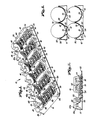
- Figure 1 is a perspective view of a dunnage support in accordance with the invention
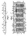
- Fig. 2 is a plan view of the support depicted in Fig. 1
- Fig. 3 is a side elevational view of the support illustrated in Figs. 1 and 2, viewing the front side thereof
- Fig. 4 is a side elevational view of the dunnage support of Figs. 1-3, depicting the rear side thereof
- Fig. 7 is a sectional view taken along line 7-7 of Fig. 4
- Fig. 8 is a fragmentary vertical sectional view illustrating a pair of dunnage supports in use, with the supports in operative, supporting engagement with fluorescent tubes
- Fig. 9 is a front side elevational view of an interfitted stack of dunnage supports in accordance with the invention, illustrating the provision of substantially uniform, laterally extending spaces between individual supports permitting ready machine dispensing of the supports.
- the support 10 is in the form of an integral, thermo-formed body of synthetic resin material. Most preferably, the material is polyvinyl chloride sheeting having an initial thickness before forming of 0,36mm (0.014 inches).
- the support 10 includes an upstanding rear sidewall 12, an opposed, upstanding hollow front sidewall 14, opposed end walls 16, 18, and a rearwardly extending rear side lip 20.
- the overall support 10 is further provided with a total of six concavo-convex wall sections 22 which cooperatively present a plurality of individual, elongated, open-top, parallel, juxtaposed concave tube-receiving sockets or regions 24. It will be noted in this respect that the regions 24 terminate at rear wall 12, and accordingly, the wall 12 presents in overall configuration a scalloped appearance.
- the wall sections 22 are joined at their respective apices by means of elongated, rectangular, fore and aft extending connector walls 26, the latter being notched as at 28 adjacent front wall 14.
- the endmost wall sections 22 are joined to the adjacent end walls 16, 18, by means of a similar connector wall 30, each of the latter being provided with three spaced apart upstanding spacers 32.
- rear sidewall 12 is integrally joined with each of the sidewalls 16, 18, at smooth, rounded rear corners 34.
- the wall 12 is provided with a total of five formed recesses 36 therein, respectively located directly beneath an associated connector wall 26 in the region between the tube-receiving regions 24.
- FIGs. 1 and 3 depict the particular construction of front wall 14.
- the front wall 14 is integrally connected with the sidewalls 16, 18 at smooth, rounded corners 38.
- the front wall 14 includes a series of openings 40 therein respectively in communication and alignment with the corresponding tube-receiving regions 24.
- four openings 40 of relatively deep configuration are provided, along with two openings 40a of somewhat shallower configuration.
- the openings 40, 40a are designed to receive and accommodate the connector prongs of fluorescent tubes received within the supports, as those skilled in the art will readily appreciate.
- each of the recesses 40, 40a at the left hand margin thereof as viewed in Figs.
- the support includes a somewhat triangularly-shaped ledge or platform 42 and a correspondingly shaped relieved zone.
- the platforms 42 and relieved zones are provided at the righthand margin of each recess 40, 40a, as opposed to the configuration specifically depicted in Fig. 1.
- the left and righthand placement of platforms 43 would alternate in the stack so as to establish and maintain a proper spacing between individual interfitted supports.
- front wall 14 is provided with a total of five somewhat triangularly shaped, arcuate in cross section, open top, upwardly diverging recessed zones 44. These zones are defined by correspondingly shaped indentations in wall 14 as will be readily seen, with such indentations being in opposed relationship to each of the five connector walls 26 (see Fig. 2). As a result of this configuration, it will be perceived that each of the connector walls 26, at the region of front wall 14, is somewhat Y-shaped in configuration, with the base of the Y extending from the corresponding notch 28, and with the bifurcated portion thereof surrounding and defining the upper end of each zone 44. As readily observable from Figs.
- front wall 14 presents an effective thickness attributable to the noted Y-shaped sections together with the bottom walls 46 and 46a of the respective openings 40 and 40a.
- the overall front wall 14 presents an upright inner surface in the form of respective arcuate walls 48 joined to the Y-shaped sections and opening-defining walls and extending downwardly therefrom for joinder with the concavo-convex walls 22.
- the arcuate walls 48 in turn define an upright abutment surface for the end of a fluorescent tube situated within each corresponding region 24.
- Rear side lip 20 is provided with a plurality, here seven, of upstanding spacer nibs 50.
- the nibs 50 in the depicted embodiment, are located at the ends of the lip 20, and just to the left of each recess 36. The purpose of these nibs 50 will be made clear hereinafter.
- Each of the concavo-convex wall sections 22 include a stepped, arcuate, end cap-receiving wall portion 52 which extends rearwardly from each associated wall 48 and terminates at the frontmost end of the associated notches 28 as shown.
- the wall portions 52 as indicated receive the metallic end caps provided on the fluorescent tubes.
- each concavo-convex wall section 22 includes a plurality of axially spaced apart, arcuate, upwardly opening and diverging wall sections 56 presenting a radius of curvature conforming to that of the sidewall of a fluorescent tube.
- These spaced apart wall sections 56 at their respective side margins, merge into and form a part of similarly curved main sidewall portions 58 which extend upwardly and are integral with the upper connector walls 26.
- the concavo-convex walls 22 further include a second plurality of downwardly opening and diverging wall portions 54 which similarly have a radius of curvature conforming to the sidewall of a fluorescent tube.
- the respective marginal ends of each wall section 54 are joined with upwardly extending walls 60 (see Fig. 8) which extend upwardly to merge into main wall portion 58.
- the alternating walls sections 54, 56 are joined together by means of vertical walls 62 in order to maintain the wall sections in vertically spaced relationship to one another.
- each upwardly opening wall section 56 is spaced above the adjacent wall section 54. Indeed, the lateral side margins of the wall sections 54 extend slightly below the bottom edge of the sidewalls 16, 18, and rear wall 14.
- each of the wall sections 54, 56 is provided with a plurality of relatively small cushioning striations or ribs 64 formed therein during the vacuum forming process of the dunnage support 10.
- each end cap-receiving wall portion 52 is similarly striated.
- the element 10 is formed in a female mold so that the thickness of each of the upper connector walls 26, 30 is greater than that of the lower downwardly opening walls sections 54. Indeed, the thickness of the endmost portions of the wall sections 54 are on the order of 0.10mm (0.004 inch), and are effectively transluscent. On the other hand, the connector walls 26, 30 are virtually the same thickness as the starting sheet material, or preferably about 0.36mm (0.014 inch).
- FIG. 9 depicts a vertical stack 66 of interfitted dunnage supports in accordance with the invention.
- This stack is made up of two particular embodiments of the dunnage supports, namely the supports 10 fully described above, together with alternating supports 10a.
- the supports 10a are in all respects identical with the supports 10, save for the fact that in the supports 10a, the nibs 50a thereof are laterally offset from the nibs 50 of the supports 10, and the ledges or platforms thereof (not shown) are laterally offset from the platforms 42.
- the nibs 50, 50a alternate in a stairstep fashion throughout the stack 66; furthermore, the spacing platforms of the supports 10, 10a similarly alternate in a stairstep fashion.
- each of the nibs 50, 50a contacts the planar underside of the lip of the support next above in the stack; likewise, each individual set of ledges or platforms engages the full heighth wall of the Y-shaped section of the next adjacent support.
- the heighth of the nibs and the vertical recess of the platforms are correlated so as to maintain an even spacing between individual supports about the entire periphery thereof. This prevents full nesting of the respective supports 10, 10a and effectively presents a series of substantially even, elongated spaces 68 between individual dunnage supports in the stack 66.
- the stack 66 can be placed in automatic dispensing equipment, and the spaces 68 afford adequate clearance for the insertion of dispensing equipment between individual supports in the stack.
- such dispensing equipment can be used to good effect to achieve easy, high speed automated dispensing of the individual supports.
- PVC having a thickness of 0.36mm (0.014 inch) is the preferred sheet material for use in forming the supports of the invention
- other current or future equivalent materials may also be used.
- thermoplastic polyester or polyethylene terephthalate synthetic resins can also be used to good effect in the invention, with the thicknesses of these materials being substantially the same as outlined above.
- synthetic resin materials having a durometer value (Shore D per ASTM D-2240) of from about 80 to 90 (most preferably 84), and a modulus of elasticity of from about 400,000 to 440,000, ASTM D-790 (most preferably 420,000).
- the most preferred PVC material further has a specific gravity 1.35, ASTM D-792; a tensile strength of 46.5 MPa (6750 psi), ASTM D-638; a tensile modulus of 2200 MPa (315,000 psi), ASTM D-638; a flexural modulus of 2900 MPa (420,000 psi), ASTM D-790; and a deflection temperature at 1.8 MPa (264 psi) of 58°C, ASTM D-648.
- the various structural features of the dunnage supports assures that a package of fluorescent tubes with individual supports between respective layers thereof can withstand potentially destructive impact forces. That is to say, a given package containing four layers of tubes would make use of five dunnage supports at each end of the tubes, with four of the supports receiving the tubes as illustrated in Fig. 8, and with one support being inverted.
- actual testing with the dunnage elements hereof has proved that they are fully capable of supporting and protecting fluorescent tubes in a manner at least equivalent to conventional pulp dunnage supports.
- Such protection is believed to stem from the inherent flexibility of the synthetic resin material, and also by virtue of the striations 64 provided on the tube-engaging surfaces.
- the various recesses such as the notches 28 and zones 44, afford a controlled collapse to the dunnage elements which has been found to safely absorb potentially destructive forces.
- central connector wall 26 is slightly wider than the remaining connector walls on either side thereof. This not only enhances the strength of the central section of the support, but also facilitates automated insertion of thin vertical corrugated material between the central tubes during the packing process.
- a prime feature of the present invention resides in the provision of dunnage supports designed to only incompletely nest in a stack thereof so as to present uniform spacings between pairs of elements and thus facilitate machine dispensing thereof.
Landscapes
- Engineering & Computer Science (AREA)
- Mechanical Engineering (AREA)
- Ceramic Engineering (AREA)
- Buffer Packaging (AREA)
- Making Paper Articles (AREA)
- Joints With Sleeves (AREA)
- Vessels And Coating Films For Discharge Lamps (AREA)
- Luminescent Compositions (AREA)
- Packaging Frangible Articles (AREA)
Claims (5)
- Support pour tubes fluorescents qui comprend un corps d'un seul tenant (10) formé d'une feuille de résine synthétique et possédant un bord avant (14) qui présente une surface extrême inférieure allongée, s'étendant latéralement, des parois concaves-convexes (22) qui définissent un certain nombre de régions concaves (24) de réception des tubes, allongées, parallèles juxtaposées et s'ouvrant vers le haut, avec une paroi supérieure allongée (26) entre les régions (24) juxtaposées, les parois (22) définissant des régions qui comprend une première pluralité de premières sections de parois incurvées (56), de contact avec les tubes, espacées axialement, et s'ouvrant et divergeant vers le haut, chacune de ces sections possédant un arrondi qui épouse de façon générale la forme de la paroi latérale circulaire d'un tube fluorescent, et une deuxième pluralité de deuxièmes sections de parois incurvées (54) de contact avec les tubes, espacées axialement, et s'ouvrant et divergeant vers le bas, chacune de ces sections possédant un arrondi qui épouse de façon générale la paroi latérale circulaire d'un tube fluorescent, les premières et deuxièmes sections de parois (56, 54) de contact avec les tubes étant munies chacune de surfaces ondulées de contact des tubes,
la feuille de résine possédant une épaisseur avant le formage d'environ 0,33 à 0,46 mm (0,013 à 0,018 pouce), les premières sections de parois (56) s'ouvrant vers le haut et les deuxièmes sections de paroi (54) s'ouvrant vers le bas alternant sur la longueur de chacune des régions (24), les extrémités latérales des sections de paroi (54) s'ouvrant vers le bas étant situées dans la partie la plus basse du support (10) dans la direction verticale lorsque le support est orienté horizontalement, des sections de parois (62) verticales reliant les premières et deuxièmes sections de parois (56, 54) ; et
des entretoises (32, 36, 42, 50) étant prévues pour empêcher plusieurs supports de s'emboîter entièrement les uns dans les autres, et pour définir des espaces allongés (68), orientés latéralement, sensiblement uniformes, entre les supports (10) emboîtés adjacents, prévus pour permettre d'insérer un équipement de distribution automatique entre les supports, les espaces (68) ayant une hauteur verticale d'au moins en-viron 3,18 mm (1/8 pouce), les entretoises (32, 36, 42, 50) comprenant une structure capable de créer un espace vertical entre les parois supérieures (26) des supports (10) adjacents emboîtés les uns dans les autres dans une pile de ces supports, pour faciliter la séparation des supports individuels de la pile. - Support selon la revendication 1, caractérisé en ce que chacun desdits supports présente une lèvre latérale arrière allongée (20) s'étendant vers l'arrière, qui possède une face inférieure présentant une surface de butée, lesdites lèvres latérales arrière (20) des supports (10) de la pile étant sensiblement parallèles et dans des positions relatives superposées, espacées verticalement les unes des autres, lesdites entretoises comprenant une pluralité de bosses (50) dirigées vers le haut, espacées latéralement, portées par chaque lèvre et orientées de manière à entrer en contact avec la surface de butée présentée par la lèvre (20) du support de tubes (10) immédiatement supérieur.
- Support selon la revendication 2, dans lequel les bosses portées par chaque support sont déportées latéralement par rapport aux bosses portées par la lèvre du support de tubes immédiatement supérieur.
- Support selon la revendication 1, dans le-quel lesdits supports sont formés d'une feuille de polychlorure de vinyle.
- Support selon la revendication 1, dans lequel lesdites entretoises comprennent une structure définissant une pluralité de plates-formes ou replats (42) espacés latéralement, le long du bord latéral avant de chaque support (10), la plate-forme ou replat (42) de chaque support étant déporté latéralement par rapport au replat porté par le support de tubes immédiatement supérieur.
Priority Applications (1)
| Application Number | Priority Date | Filing Date | Title |
|---|---|---|---|
| AT87101728T ATE64913T1 (de) | 1986-08-11 | 1987-02-09 | Verpackungszwischenlage fuer fluoreszierende roehren. |
Applications Claiming Priority (2)
| Application Number | Priority Date | Filing Date | Title |
|---|---|---|---|
| US895507 | 1986-08-11 | ||
| US06/895,507 US4705170A (en) | 1986-08-11 | 1986-08-11 | Fluorescent tube dunnage |
Related Child Applications (1)
| Application Number | Title | Priority Date | Filing Date |
|---|---|---|---|
| EP90113647.3 Division-Into | 1987-02-09 |
Publications (3)
| Publication Number | Publication Date |
|---|---|
| EP0257177A2 EP0257177A2 (fr) | 1988-03-02 |
| EP0257177A3 EP0257177A3 (en) | 1988-09-14 |
| EP0257177B1 true EP0257177B1 (fr) | 1991-07-03 |
Family
ID=25404607
Family Applications (1)
| Application Number | Title | Priority Date | Filing Date |
|---|---|---|---|
| EP87101728A Expired - Lifetime EP0257177B1 (fr) | 1986-08-11 | 1987-02-09 | Elément intercalaire pour emballage de tubes fluorescents |
Country Status (9)
| Country | Link |
|---|---|
| US (1) | US4705170A (fr) |
| EP (1) | EP0257177B1 (fr) |
| JP (1) | JPS6344479A (fr) |
| AT (1) | ATE64913T1 (fr) |
| AU (1) | AU594411B2 (fr) |
| CA (1) | CA1291081C (fr) |
| DE (1) | DE3771145D1 (fr) |
| ES (1) | ES2022169B3 (fr) |
| GR (1) | GR3002250T3 (fr) |
Families Citing this family (27)
| Publication number | Priority date | Publication date | Assignee | Title |
|---|---|---|---|---|
| US4796756A (en) * | 1988-04-11 | 1989-01-10 | Silor Optical Of Florida, Inc. | Optical lens carrier |
| JPH02109850A (ja) * | 1988-10-19 | 1990-04-23 | Tanaka Kikinzoku Kogyo Kk | 刷子接点の梱包ケース |
| US4942965A (en) * | 1989-07-03 | 1990-07-24 | Comer Robert E | Elongated tray for supporting tubular objects |
| US4936453A (en) * | 1989-08-21 | 1990-06-26 | The Lawrence Paper Company | Compact fluorescent tube dunnage element |
| US5080314A (en) * | 1990-04-06 | 1992-01-14 | Henry Molded Products, Inc. | Roll stacker |
| US5016751A (en) * | 1990-08-16 | 1991-05-21 | Lawrence Paper Company | Molded flourescent tube dunnage element |
| US5058744A (en) * | 1990-08-17 | 1991-10-22 | The Lawrence Paper Company | Minimum length fluoroescent tube dunnage element |
| US5515976A (en) * | 1995-08-18 | 1996-05-14 | Plastofilm Industries, Inc. | Packaging for fragile articles within container |
| US5695057A (en) * | 1996-03-18 | 1997-12-09 | Lawrence Paper Company | Thermo-formed packing element for flourescent tube |
| US6041933A (en) * | 1999-02-01 | 2000-03-28 | Jamestown Plastics, Inc. | Nestable and stackable two-piece dunnage |
| US6474613B2 (en) | 1999-06-11 | 2002-11-05 | O'malley Joseph | High storage density roll stock stacking support |
| US6209839B1 (en) | 1999-06-11 | 2001-04-03 | O'malley Joseph | Plastic stacking support for roll stock |
| US7044358B2 (en) | 2001-04-17 | 2006-05-16 | Gratz Jeffrey J | Two-sided roll support with multiple ribs |
| GB0203211D0 (en) * | 2002-02-11 | 2002-03-27 | Matheou Stefano | Device for stacking cylindrical objects |
| US7237675B2 (en) * | 2002-04-09 | 2007-07-03 | O'malley Joseph | Bottle cradle stacking support |
| USD480306S1 (en) | 2002-08-12 | 2003-10-07 | Fibreform Containers, Inc. | Narrow roll support |
| US6997340B1 (en) | 2003-04-21 | 2006-02-14 | Honda Giken Kogyo Kabushiki Kaisha | Ergonomic packs for production supply |
| US20090090653A1 (en) * | 2003-10-29 | 2009-04-09 | Valoris L Forsyth | Low cost wafer box improvements |
| US7131617B2 (en) * | 2003-11-19 | 2006-11-07 | Rsvp Operations, Llc | Modified spring system end cap for packaging fragile articles within shipping cartons |
| CA2661961A1 (fr) * | 2006-09-08 | 2008-03-13 | Unilever Plc | Systeme de stockage |
| US8646603B2 (en) * | 2011-10-12 | 2014-02-11 | Tekni-Plex, Inc. | Apparatus and method for aligning and holding light bulbs |
| JP6246678B2 (ja) * | 2014-08-22 | 2017-12-13 | 日立アプライアンス株式会社 | 直管形ランプの梱包体 |
| CN104875955B (zh) * | 2015-06-15 | 2016-11-30 | 浙江天衣机械有限公司 | 钢管支撑架以及钢管支撑装置 |
| AT16493U1 (de) * | 2016-11-22 | 2019-10-15 | Blum Gmbh Julius | Verwendung eines Transportbehälters zur Aufnahme mindestens eines Möbelbeschlages |
| CN107054899B (zh) * | 2017-06-06 | 2018-10-23 | 宁波高瑞照明有限公司 | 一种日光灯管运输箱 |
| EP4269275A4 (fr) * | 2020-12-28 | 2024-07-03 | Asahi Kasei Medical Co., Ltd. | Matériau d'emballage, corps emballé, ensemble module et procédé d'emballage de module |
| CN115072173A (zh) * | 2022-07-13 | 2022-09-20 | 中建八局轨道交通建设有限公司 | 物料堆放装置 |
Family Cites Families (28)
| Publication number | Priority date | Publication date | Assignee | Title |
|---|---|---|---|---|
| CA645857A (en) * | 1962-07-31 | Keyes Fibre Company | De-nestable molded pulp trays | |
| US1347909A (en) * | 1919-08-15 | 1920-07-27 | Perris Isidor | Filler for egg-crates and the like |
| US2564834A (en) * | 1946-11-23 | 1951-08-21 | James H Devine | Receptacle and cover therefor |
| US2639807A (en) * | 1949-12-24 | 1953-05-26 | Louis C Ambrette | Shipping package for press inking rolls |
| US2808189A (en) * | 1953-11-16 | 1957-10-01 | Keyes Fibre Co | Packing material for fragile articles |
| US2815856A (en) * | 1954-10-04 | 1957-12-10 | Keyes Fibre Co | Packing case for pilsener glasses |
| US2776772A (en) * | 1956-06-05 | 1957-01-08 | Itoda Tamotsu | Packing devices for stacked nested frangible articles |
| US3018015A (en) * | 1957-10-02 | 1962-01-23 | Agriss Norton | Resilient packing sheet |
| US3119492A (en) * | 1961-11-29 | 1964-01-28 | Du Pont | Tray packages |
| US3163312A (en) * | 1962-06-29 | 1964-12-29 | Diamond National Corp | Packing for fragile articles |
| US3143274A (en) * | 1962-11-01 | 1964-08-04 | Gen Electric | Fluorescent lamp carton |
| US3120901A (en) * | 1962-12-21 | 1964-02-11 | Packaging Corp America | Molded egg tray |
| US3195770A (en) * | 1963-02-18 | 1965-07-20 | Holley Plastics Company | Plastic capsule packaging |
| GB1065848A (en) * | 1963-12-24 | 1967-04-19 | Hartmann Fibre Ltd | Improvements in or relating to nestable trays |
| US3219232A (en) * | 1964-03-09 | 1965-11-23 | Banner Metals Inc | Receptacle |
| US3223234A (en) * | 1965-02-01 | 1965-12-14 | Pantasota Company | End support for fragile tubular articles |
| US3379340A (en) * | 1965-10-21 | 1968-04-23 | Silvio Paul | Stacking trays |
| US3398840A (en) * | 1966-10-24 | 1968-08-27 | Banner Metals Inc | Nestable-stackable receptacle |
| US3497102A (en) * | 1968-10-14 | 1970-02-24 | Packaging Corp America | Tray construction |
| US3589511A (en) * | 1969-08-13 | 1971-06-29 | Owens Illinois Inc | Package and tray for tubes or the like |
| US3740238A (en) * | 1971-01-04 | 1973-06-19 | S Graham | Stackable cookie package and tray |
| US3708084A (en) * | 1971-01-29 | 1973-01-02 | Diamond Int Corp | Packing for fragile articles |
| US3777885A (en) * | 1971-08-23 | 1973-12-11 | Rehkopf Ind Inc | Locking material-handling tray |
| FR2155005A5 (en) * | 1971-10-04 | 1973-05-18 | Lumbres Papeteries | Bottle pack trays - as contoured expanded mouldings which positively locate alternating rows and layers of bottles |
| US3786932A (en) * | 1971-10-08 | 1974-01-22 | Schlegel Co Ca Ltd | Core trays |
| US3771646A (en) * | 1972-06-28 | 1973-11-13 | Plastofilm Ind Inc | Shipping holder for spark plugs or the like |
| USD249638S (en) | 1976-12-27 | 1978-09-26 | Keyes Fibre Company | Packing tray for fluorescent tubes |
| US4427730A (en) * | 1982-04-26 | 1984-01-24 | Keyes Fibre Company | Tube packing sheet with spaced support surfaces |
-
1986
- 1986-08-11 US US06/895,507 patent/US4705170A/en not_active Expired - Fee Related
-
1987
- 1987-01-06 CA CA000526729A patent/CA1291081C/fr not_active Expired - Fee Related
- 1987-01-07 AU AU67188/87A patent/AU594411B2/en not_active Ceased
- 1987-02-05 JP JP62025539A patent/JPS6344479A/ja active Pending
- 1987-02-09 DE DE8787101728T patent/DE3771145D1/de not_active Expired - Fee Related
- 1987-02-09 ES ES87101728T patent/ES2022169B3/es not_active Expired - Lifetime
- 1987-02-09 EP EP87101728A patent/EP0257177B1/fr not_active Expired - Lifetime
- 1987-02-09 AT AT87101728T patent/ATE64913T1/de not_active IP Right Cessation
-
1991
- 1991-07-04 GR GR91400838T patent/GR3002250T3/el unknown
Also Published As
| Publication number | Publication date |
|---|---|
| AU594411B2 (en) | 1990-03-08 |
| JPS6344479A (ja) | 1988-02-25 |
| EP0257177A2 (fr) | 1988-03-02 |
| ES2022169B3 (es) | 1991-12-01 |
| US4705170A (en) | 1987-11-10 |
| GR3002250T3 (en) | 1992-12-30 |
| CA1291081C (fr) | 1991-10-22 |
| DE3771145D1 (de) | 1991-08-08 |
| AU6718887A (en) | 1988-02-18 |
| ATE64913T1 (de) | 1991-07-15 |
| EP0257177A3 (en) | 1988-09-14 |
Similar Documents
| Publication | Publication Date | Title |
|---|---|---|
| EP0257177B1 (fr) | Elément intercalaire pour emballage de tubes fluorescents | |
| US4792045A (en) | Fluorescent tube dunnage | |
| US4410099A (en) | Case for multipacks of bottles | |
| US3589511A (en) | Package and tray for tubes or the like | |
| US6010007A (en) | Thermoformed fragility packaging | |
| US4040517A (en) | Stacking case | |
| US3997057A (en) | Stacking means for packing tray | |
| US3282458A (en) | Nestable egg trays | |
| US5048716A (en) | Cardboard container with reinforcing slits lined with synthetic material | |
| CA1215023A (fr) | Emballage compartimente pour tubes | |
| US4942965A (en) | Elongated tray for supporting tubular objects | |
| US4936453A (en) | Compact fluorescent tube dunnage element | |
| EP0908401B1 (fr) | Plateau pour oeufs | |
| US3223234A (en) | End support for fragile tubular articles | |
| US20230159262A1 (en) | Egg Carton with Separate Base and Lid Configurations and Moisture Venting | |
| US3865299A (en) | Egg carton with flexible window well | |
| EP0481992A4 (en) | Low depth, nestable tray for fluid containers | |
| EP0521705A1 (fr) | Empiler des articles pour le stockage et/ou pour le transit | |
| US8646603B2 (en) | Apparatus and method for aligning and holding light bulbs | |
| US10227157B2 (en) | Egg carton with diagonal lid panel | |
| EP0398398A1 (fr) | Support pour tube fluorescent | |
| EP0696543A1 (fr) | Empilement d'articles pour le stockage et/ou pour le transit | |
| EP0610100B1 (fr) | Plateau de stockage et empilage d'articles | |
| CN219008527U (zh) | 酒瓶打包用载具 | |
| EP0026535B1 (fr) | Caisse ou plateau en matière plastique |
Legal Events
| Date | Code | Title | Description |
|---|---|---|---|
| PUAI | Public reference made under article 153(3) epc to a published international application that has entered the european phase |
Free format text: ORIGINAL CODE: 0009012 |
|
| AK | Designated contracting states |
Kind code of ref document: A2 Designated state(s): AT BE CH DE ES FR GB GR IT LI LU NL SE |
|
| PUAL | Search report despatched |
Free format text: ORIGINAL CODE: 0009013 |
|
| AK | Designated contracting states |
Kind code of ref document: A3 Designated state(s): AT BE CH DE ES FR GB GR IT LI LU NL SE |
|
| 17P | Request for examination filed |
Effective date: 19881230 |
|
| 17Q | First examination report despatched |
Effective date: 19890530 |
|
| GRAA | (expected) grant |
Free format text: ORIGINAL CODE: 0009210 |
|
| AK | Designated contracting states |
Kind code of ref document: B1 Designated state(s): AT BE CH DE ES FR GB GR IT LI LU NL SE |
|
| REF | Corresponds to: |
Ref document number: 64913 Country of ref document: AT Date of ref document: 19910715 Kind code of ref document: T |
|
| XX | Miscellaneous (additional remarks) |
Free format text: TEILANMELDUNG 90113647.3 EINGEREICHT AM 09/02/87. |
|
| REF | Corresponds to: |
Ref document number: 3771145 Country of ref document: DE Date of ref document: 19910808 |
|
| ITF | It: translation for a ep patent filed | ||
| ET | Fr: translation filed | ||
| PLBE | No opposition filed within time limit |
Free format text: ORIGINAL CODE: 0009261 |
|
| STAA | Information on the status of an ep patent application or granted ep patent |
Free format text: STATUS: NO OPPOSITION FILED WITHIN TIME LIMIT |
|
| 26N | No opposition filed | ||
| REG | Reference to a national code |
Ref country code: GR Ref legal event code: FG4A Free format text: 3002250 |
|
| PGFP | Annual fee paid to national office [announced via postgrant information from national office to epo] |
Ref country code: FR Payment date: 19930111 Year of fee payment: 7 Ref country code: CH Payment date: 19930111 Year of fee payment: 7 |
|
| PGFP | Annual fee paid to national office [announced via postgrant information from national office to epo] |
Ref country code: DE Payment date: 19930112 Year of fee payment: 7 |
|
| PGFP | Annual fee paid to national office [announced via postgrant information from national office to epo] |
Ref country code: SE Payment date: 19930113 Year of fee payment: 7 |
|
| PGFP | Annual fee paid to national office [announced via postgrant information from national office to epo] |
Ref country code: LU Payment date: 19930114 Year of fee payment: 7 Ref country code: AT Payment date: 19930114 Year of fee payment: 7 |
|
| PGFP | Annual fee paid to national office [announced via postgrant information from national office to epo] |
Ref country code: BE Payment date: 19930125 Year of fee payment: 7 |
|
| PGFP | Annual fee paid to national office [announced via postgrant information from national office to epo] |
Ref country code: GR Payment date: 19930128 Year of fee payment: 7 |
|
| PGFP | Annual fee paid to national office [announced via postgrant information from national office to epo] |
Ref country code: GB Payment date: 19930129 Year of fee payment: 7 |
|
| PGFP | Annual fee paid to national office [announced via postgrant information from national office to epo] |
Ref country code: ES Payment date: 19930216 Year of fee payment: 7 |
|
| PGFP | Annual fee paid to national office [announced via postgrant information from national office to epo] |
Ref country code: NL Payment date: 19930228 Year of fee payment: 7 |
|
| EPTA | Lu: last paid annual fee | ||
| PG25 | Lapsed in a contracting state [announced via postgrant information from national office to epo] |
Ref country code: LU Free format text: LAPSE BECAUSE OF NON-PAYMENT OF DUE FEES Effective date: 19940209 Ref country code: GB Effective date: 19940209 Ref country code: AT Effective date: 19940209 |
|
| PG25 | Lapsed in a contracting state [announced via postgrant information from national office to epo] |
Ref country code: SE Effective date: 19940210 Ref country code: ES Free format text: LAPSE BECAUSE OF NON-PAYMENT OF DUE FEES Effective date: 19940210 |
|
| PG25 | Lapsed in a contracting state [announced via postgrant information from national office to epo] |
Ref country code: LI Effective date: 19940228 Ref country code: CH Effective date: 19940228 Ref country code: BE Effective date: 19940228 |
|
| BERE | Be: lapsed |
Owner name: LAWRENCE PAPER CY Effective date: 19940228 |
|
| PG25 | Lapsed in a contracting state [announced via postgrant information from national office to epo] |
Ref country code: GR Free format text: THE PATENT HAS BEEN ANNULLED BY A DECISION OF A NATIONAL AUTHORITY Effective date: 19940831 |
|
| PG25 | Lapsed in a contracting state [announced via postgrant information from national office to epo] |
Ref country code: NL Effective date: 19940901 |
|
| GBPC | Gb: european patent ceased through non-payment of renewal fee |
Effective date: 19940209 |
|
| NLV4 | Nl: lapsed or anulled due to non-payment of the annual fee | ||
| PG25 | Lapsed in a contracting state [announced via postgrant information from national office to epo] |
Ref country code: FR Effective date: 19941031 |
|
| REG | Reference to a national code |
Ref country code: CH Ref legal event code: PL |
|
| PG25 | Lapsed in a contracting state [announced via postgrant information from national office to epo] |
Ref country code: DE Effective date: 19941101 |
|
| REG | Reference to a national code |
Ref country code: FR Ref legal event code: ST Ref country code: GR Ref legal event code: MM2A Free format text: 3002250 |
|
| EUG | Se: european patent has lapsed |
Ref document number: 87101728.1 Effective date: 19940910 |
|
| REG | Reference to a national code |
Ref country code: ES Ref legal event code: FD2A Effective date: 19990201 |
|
| PG25 | Lapsed in a contracting state [announced via postgrant information from national office to epo] |
Ref country code: IT Free format text: LAPSE BECAUSE OF NON-PAYMENT OF DUE FEES;WARNING: LAPSES OF ITALIAN PATENTS WITH EFFECTIVE DATE BEFORE 2007 MAY HAVE OCCURRED AT ANY TIME BEFORE 2007. THE CORRECT EFFECTIVE DATE MAY BE DIFFERENT FROM THE ONE RECORDED. Effective date: 20050209 |