EP0257265A2 - Dieselkraftstoff-Filter/Wasserabscheider - Google Patents
Dieselkraftstoff-Filter/Wasserabscheider Download PDFInfo
- Publication number
- EP0257265A2 EP0257265A2 EP87110071A EP87110071A EP0257265A2 EP 0257265 A2 EP0257265 A2 EP 0257265A2 EP 87110071 A EP87110071 A EP 87110071A EP 87110071 A EP87110071 A EP 87110071A EP 0257265 A2 EP0257265 A2 EP 0257265A2
- Authority
- EP
- European Patent Office
- Prior art keywords
- cartridge
- housing
- separating device
- support housing
- communicating
- Prior art date
- Legal status (The legal status is an assumption and is not a legal conclusion. Google has not performed a legal analysis and makes no representation as to the accuracy of the status listed.)
- Withdrawn
Links
Images

Classifications
-
- C—CHEMISTRY; METALLURGY
- C10—PETROLEUM, GAS OR COKE INDUSTRIES; TECHNICAL GASES CONTAINING CARBON MONOXIDE; FUELS; LUBRICANTS; PEAT
- C10G—CRACKING HYDROCARBON OILS; PRODUCTION OF LIQUID HYDROCARBON MIXTURES, e.g. BY DESTRUCTIVE HYDROGENATION, OLIGOMERISATION, POLYMERISATION; RECOVERY OF HYDROCARBON OILS FROM OIL-SHALE, OIL-SAND, OR GASES; REFINING MIXTURES MAINLY CONSISTING OF HYDROCARBONS; REFORMING OF NAPHTHA; MINERAL WAXES
- C10G33/00—Dewatering or demulsification of hydrocarbon oils
- C10G33/06—Dewatering or demulsification of hydrocarbon oils with mechanical means, e.g. by filtration
-
- B—PERFORMING OPERATIONS; TRANSPORTING
- B01—PHYSICAL OR CHEMICAL PROCESSES OR APPARATUS IN GENERAL
- B01D—SEPARATION
- B01D17/00—Separation of liquids, not provided for elsewhere, e.g. by thermal diffusion
- B01D17/02—Separation of non-miscible liquids
- B01D17/0208—Separation of non-miscible liquids by sedimentation
-
- B—PERFORMING OPERATIONS; TRANSPORTING
- B01—PHYSICAL OR CHEMICAL PROCESSES OR APPARATUS IN GENERAL
- B01D—SEPARATION
- B01D17/00—Separation of liquids, not provided for elsewhere, e.g. by thermal diffusion
- B01D17/02—Separation of non-miscible liquids
- B01D17/04—Breaking emulsions
- B01D17/045—Breaking emulsions with coalescers
-
- B—PERFORMING OPERATIONS; TRANSPORTING
- B01—PHYSICAL OR CHEMICAL PROCESSES OR APPARATUS IN GENERAL
- B01D—SEPARATION
- B01D17/00—Separation of liquids, not provided for elsewhere, e.g. by thermal diffusion
- B01D17/08—Thickening liquid suspensions by filtration
- B01D17/10—Thickening liquid suspensions by filtration with stationary filtering elements
-
- B—PERFORMING OPERATIONS; TRANSPORTING
- B01—PHYSICAL OR CHEMICAL PROCESSES OR APPARATUS IN GENERAL
- B01D—SEPARATION
- B01D27/00—Cartridge filters of the throw-away type
- B01D27/04—Cartridge filters of the throw-away type with cartridges made of a piece of unitary material, e.g. filter paper
- B01D27/06—Cartridge filters of the throw-away type with cartridges made of a piece of unitary material, e.g. filter paper with corrugated, folded or wound material
-
- B—PERFORMING OPERATIONS; TRANSPORTING
- B01—PHYSICAL OR CHEMICAL PROCESSES OR APPARATUS IN GENERAL
- B01D—SEPARATION
- B01D35/00—Filtering devices having features not specifically covered by groups B01D24/00 - B01D33/00, or for applications not specifically covered by groups B01D24/00 - B01D33/00; Auxiliary devices for filtration; Filter housing constructions
- B01D35/14—Safety devices specially adapted for filtration; Devices for indicating clogging
- B01D35/143—Filter condition indicators
-
- B—PERFORMING OPERATIONS; TRANSPORTING
- B01—PHYSICAL OR CHEMICAL PROCESSES OR APPARATUS IN GENERAL
- B01D—SEPARATION
- B01D35/00—Filtering devices having features not specifically covered by groups B01D24/00 - B01D33/00, or for applications not specifically covered by groups B01D24/00 - B01D33/00; Auxiliary devices for filtration; Filter housing constructions
- B01D35/18—Heating or cooling the filters
-
- B—PERFORMING OPERATIONS; TRANSPORTING
- B01—PHYSICAL OR CHEMICAL PROCESSES OR APPARATUS IN GENERAL
- B01D—SEPARATION
- B01D36/00—Filter circuits or combinations of filters with other separating devices
- B01D36/001—Filters in combination with devices for the removal of gas, air purge systems
-
- B—PERFORMING OPERATIONS; TRANSPORTING
- B01—PHYSICAL OR CHEMICAL PROCESSES OR APPARATUS IN GENERAL
- B01D—SEPARATION
- B01D36/00—Filter circuits or combinations of filters with other separating devices
- B01D36/003—Filters in combination with devices for the removal of liquids
-
- F—MECHANICAL ENGINEERING; LIGHTING; HEATING; WEAPONS; BLASTING
- F02—COMBUSTION ENGINES; HOT-GAS OR COMBUSTION-PRODUCT ENGINE PLANTS
- F02M—SUPPLYING COMBUSTION ENGINES IN GENERAL WITH COMBUSTIBLE MIXTURES OR CONSTITUENTS THEREOF
- F02M37/00—Apparatus or systems for feeding liquid fuel from storage containers to carburettors or fuel-injection apparatus; Arrangements for purifying liquid fuel specially adapted for, or arranged on, internal-combustion engines
- F02M37/22—Arrangements for purifying liquid fuel specially adapted for, or arranged on, internal-combustion engines, e.g. arrangements in the feeding system
- F02M37/24—Arrangements for purifying liquid fuel specially adapted for, or arranged on, internal-combustion engines, e.g. arrangements in the feeding system characterised by water separating means
- F02M37/26—Arrangements for purifying liquid fuel specially adapted for, or arranged on, internal-combustion engines, e.g. arrangements in the feeding system characterised by water separating means with water detection means
- F02M37/28—Arrangements for purifying liquid fuel specially adapted for, or arranged on, internal-combustion engines, e.g. arrangements in the feeding system characterised by water separating means with water detection means with means activated by the presence of water, e.g. alarms or means for automatic drainage
-
- F—MECHANICAL ENGINEERING; LIGHTING; HEATING; WEAPONS; BLASTING
- F02—COMBUSTION ENGINES; HOT-GAS OR COMBUSTION-PRODUCT ENGINE PLANTS
- F02M—SUPPLYING COMBUSTION ENGINES IN GENERAL WITH COMBUSTIBLE MIXTURES OR CONSTITUENTS THEREOF
- F02M37/00—Apparatus or systems for feeding liquid fuel from storage containers to carburettors or fuel-injection apparatus; Arrangements for purifying liquid fuel specially adapted for, or arranged on, internal-combustion engines
- F02M37/22—Arrangements for purifying liquid fuel specially adapted for, or arranged on, internal-combustion engines, e.g. arrangements in the feeding system
- F02M37/30—Arrangements for purifying liquid fuel specially adapted for, or arranged on, internal-combustion engines, e.g. arrangements in the feeding system characterised by heating means
-
- F—MECHANICAL ENGINEERING; LIGHTING; HEATING; WEAPONS; BLASTING
- F02—COMBUSTION ENGINES; HOT-GAS OR COMBUSTION-PRODUCT ENGINE PLANTS
- F02M—SUPPLYING COMBUSTION ENGINES IN GENERAL WITH COMBUSTIBLE MIXTURES OR CONSTITUENTS THEREOF
- F02M37/00—Apparatus or systems for feeding liquid fuel from storage containers to carburettors or fuel-injection apparatus; Arrangements for purifying liquid fuel specially adapted for, or arranged on, internal-combustion engines
- F02M37/22—Arrangements for purifying liquid fuel specially adapted for, or arranged on, internal-combustion engines, e.g. arrangements in the feeding system
- F02M37/32—Arrangements for purifying liquid fuel specially adapted for, or arranged on, internal-combustion engines, e.g. arrangements in the feeding system characterised by filters or filter arrangements
- F02M37/40—Arrangements for purifying liquid fuel specially adapted for, or arranged on, internal-combustion engines, e.g. arrangements in the feeding system characterised by filters or filter arrangements with means for detection of clogging
-
- F—MECHANICAL ENGINEERING; LIGHTING; HEATING; WEAPONS; BLASTING
- F02—COMBUSTION ENGINES; HOT-GAS OR COMBUSTION-PRODUCT ENGINE PLANTS
- F02B—INTERNAL-COMBUSTION PISTON ENGINES; COMBUSTION ENGINES IN GENERAL
- F02B1/00—Engines characterised by fuel-air mixture compression
- F02B1/02—Engines characterised by fuel-air mixture compression with positive ignition
- F02B1/04—Engines characterised by fuel-air mixture compression with positive ignition with fuel-air mixture admission into cylinder
-
- F—MECHANICAL ENGINEERING; LIGHTING; HEATING; WEAPONS; BLASTING
- F02—COMBUSTION ENGINES; HOT-GAS OR COMBUSTION-PRODUCT ENGINE PLANTS
- F02B—INTERNAL-COMBUSTION PISTON ENGINES; COMBUSTION ENGINES IN GENERAL
- F02B3/00—Engines characterised by air compression and subsequent fuel addition
- F02B3/06—Engines characterised by air compression and subsequent fuel addition with compression ignition
-
- F—MECHANICAL ENGINEERING; LIGHTING; HEATING; WEAPONS; BLASTING
- F02—COMBUSTION ENGINES; HOT-GAS OR COMBUSTION-PRODUCT ENGINE PLANTS
- F02M—SUPPLYING COMBUSTION ENGINES IN GENERAL WITH COMBUSTIBLE MIXTURES OR CONSTITUENTS THEREOF
- F02M37/00—Apparatus or systems for feeding liquid fuel from storage containers to carburettors or fuel-injection apparatus; Arrangements for purifying liquid fuel specially adapted for, or arranged on, internal-combustion engines
- F02M37/22—Arrangements for purifying liquid fuel specially adapted for, or arranged on, internal-combustion engines, e.g. arrangements in the feeding system
- F02M37/32—Arrangements for purifying liquid fuel specially adapted for, or arranged on, internal-combustion engines, e.g. arrangements in the feeding system characterised by filters or filter arrangements
- F02M37/34—Arrangements for purifying liquid fuel specially adapted for, or arranged on, internal-combustion engines, e.g. arrangements in the feeding system characterised by filters or filter arrangements by the filter structure, e.g. honeycomb, mesh or fibrous
-
- F—MECHANICAL ENGINEERING; LIGHTING; HEATING; WEAPONS; BLASTING
- F02—COMBUSTION ENGINES; HOT-GAS OR COMBUSTION-PRODUCT ENGINE PLANTS
- F02M—SUPPLYING COMBUSTION ENGINES IN GENERAL WITH COMBUSTIBLE MIXTURES OR CONSTITUENTS THEREOF
- F02M37/00—Apparatus or systems for feeding liquid fuel from storage containers to carburettors or fuel-injection apparatus; Arrangements for purifying liquid fuel specially adapted for, or arranged on, internal-combustion engines
- F02M37/22—Arrangements for purifying liquid fuel specially adapted for, or arranged on, internal-combustion engines, e.g. arrangements in the feeding system
- F02M37/54—Arrangements for purifying liquid fuel specially adapted for, or arranged on, internal-combustion engines, e.g. arrangements in the feeding system characterised by air purging means
-
- Y—GENERAL TAGGING OF NEW TECHNOLOGICAL DEVELOPMENTS; GENERAL TAGGING OF CROSS-SECTIONAL TECHNOLOGIES SPANNING OVER SEVERAL SECTIONS OF THE IPC; TECHNICAL SUBJECTS COVERED BY FORMER USPC CROSS-REFERENCE ART COLLECTIONS [XRACs] AND DIGESTS
- Y10—TECHNICAL SUBJECTS COVERED BY FORMER USPC
- Y10S—TECHNICAL SUBJECTS COVERED BY FORMER USPC CROSS-REFERENCE ART COLLECTIONS [XRACs] AND DIGESTS
- Y10S210/00—Liquid purification or separation
- Y10S210/05—Coalescer
-
- Y—GENERAL TAGGING OF NEW TECHNOLOGICAL DEVELOPMENTS; GENERAL TAGGING OF CROSS-SECTIONAL TECHNOLOGIES SPANNING OVER SEVERAL SECTIONS OF THE IPC; TECHNICAL SUBJECTS COVERED BY FORMER USPC CROSS-REFERENCE ART COLLECTIONS [XRACs] AND DIGESTS
- Y10—TECHNICAL SUBJECTS COVERED BY FORMER USPC
- Y10S—TECHNICAL SUBJECTS COVERED BY FORMER USPC CROSS-REFERENCE ART COLLECTIONS [XRACs] AND DIGESTS
- Y10S210/00—Liquid purification or separation
- Y10S210/17—Twist-on
Definitions
- This invention relates to a mechanism for separating immiscible components of a fluid mixture and, more particularly, for separating water from a diesel fuel oil/water mixture.
- diesel engines have become increasingly popular for operating motor vehicles. Although this type of engine provides increased fuel economy over the more traditional gasoline engines, diesel engines are particularly sensitive to contaminates in the fuel oil supply, particularly water mixed with the fuel oil. It is extremely difficult to maintain fuel oil supplies such that they cannot be contaminated by water. Water mixed with fuel oil has many deleterious effects on the vehicle engine, and must be separated out for the proper operation of the diesel engine, particularly in cold weather, when ice crystals may cause the filter to plug. Furthermore, diesel fuel oil contains parafin waxes which, if the fuel oil is chilled below its "cloud point", solidify into crystals, which may plug the fuel oil filter, causing a reduction or loss of fuel flow.
- Fuel oil/water separators used in motor vehicles are commonly of the pleated paper type or have some other coalescing and filtering media which effects separation. Accordingly, the media eventually is rendered ineffective or unusable. Therefore, most fuel oil/water separators have a replacable cartridge element which may be periodically removed and discarded and replaced with a fresh cartridge containing fresh coalescing and filtering media.
- the present invention provides a diesel fuel oil/water separator in which the replaceable filter/coalesce cartridge may be made very inexpensively, since the cartridge contains only the filtering and coalescing media, and does not contain the sump, draining device, and/or water detecting probe.
- the sump is a part of the base supporting the filter cartridge and providing the inlet and outlet connections therefrom. Accordingly, the sump, draining mechanism and water detecting probe are not replaced each time that the filter/coalesce cartridge is replaced, thereby substantially reducing the cost of the cartridge and considerably facilitating the removal and installation of a new cartridge.
- the diesel fuel oil/water separator generally indicated by the numeral l0 includes a removable and replaceable filter/coalesce element generally indicated by the numeral l2 and a permanently mounted base unit l4.
- the base unit l4 is permanently fixed to the motor vehicle by fasteners received through bores l6 provided in the base unit l4.
- the filter element l2 includes a conventional cupshaped sheet metal housing generally indicated by the numeral l8, the open end of which is closed by a conventional tapping plate 20.
- the tapping plate 20 includes a threaded apperature as at 22 which is threadably received on a threaded stud 24 to thereby mount the filter element l2 on the base unit l4.
- Tapping plate 20 further carries a circumferencally extending sealing member 26 at its radially outermost portion thereof which is adapted to sealingly engage a corresponding sealing surface 28 which circumscribes a portion of the base unit l4 to thereby effect a fluidtight connection between the filter element l2 and base unit l4.
- the tapping plate further carries a resilient seal 30 which includes a projecting portion 32 to engage the stud 24 to thereby effect a fluid-tight connection with the stud.
- the seal engages lower end cap 34 of a filter media generally indicated by the numeral 36, the opposite end cap 38 engages leaf spring 40 which is located against the closed end 42 of cupshaped member l8.
- a metallic center tube 44 extends between the end caps to support the filter media generally indicated by the numeral 36.
- Filter media 36 is a circumferencally extending array of radially tapering pleats, as is conventional in the filter art.
- the filter media 36 may be made out of, for example, a pleated paper having the appropriate water coalescing properties well known to those skilled in the art.
- the pleated filtering media 36 divides the interior of the cupshaped member l8 into an inlet chamber 48 which is communicated with the stud 24 and an outlet chamber 50 which is communicated with a fluid receiving cavity 52 defined by the tapping plate 20 and a corresponding surface 54 on the base unit l4, and which is circumscribed by the seal 26 and the sealing surface 28.
- the tapping plate is provided with circumferencally spaced, elongated apertures 56, which are spaced circumferencally around the periphery of the tapping plate 20, to permit communication from the chamber 50 into the fluid receiving cavity 52.
- Base unit l4 includes an inlet port 58 which is connected to the inlet fuel line and communicates the latter with a passage 60 into an inlet cavity 62.
- a valve mechanism 64 can be opened to purge air from the chamber 62 and passage 60 when the unit is initially filled with fluid.
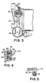
- Chamber 62 communicates through a heating element generally indicated by the numeral 66 ( Figure 4) which is installed in the inlet cavity 62 so that fuel flows through the heating element 66 before reaching a passage 65 defined within stud 24 of the base l4.
- the heating element 66 will be described hereinafter.
- Base unit l4 further includes an outlet fitting 68 which communicates with outlet chamber 70 in base unit l4 which communicates with the fluid receiving cavity 52 through passage 72.
- Outlet fitting 68 carries an annular support 69 which carries a nylon mesh separating membrane 7l which is received within outlet chamber 70. Screen 7l is conventional and separates the coalesced water droplets from the fuel passage to outlet fitting 68.
- the outlet fitting 68 is connected to the fuel line which communicates the separator assembly l0 with the vehicle engine.
- the chamber 70 is communicated with a bleed valve 74 which is more particularly illustrated in Figure 5.
- Bleed valve 74 includes a one-way flapper type check-valve 76 which permits air to be vented from the chamber 70 back to the vehicle fuel tank through outlet opening 78.
- Base unit l2 further includes a sump 82 which is communicated with the fluid receiving cavity 52 by a passage 84.
- the sump 82 is equipped with a conventional manually operated draincock 86 to permit fluid to be drained from the sump 82.
- a conventional probe 88 is installed in the sump 82 to actuate a warning device in the operator's compartment when the level of the fluid in the sump 82 attains a predetermined level.
- a conventional vacuum switch 90 is installed in the sump 82 to actuate still another warning device in the operator's compartment when a vacuum is pulled in the sump 82, thereby indicating a clogged filter condition. Accordingly, the operator is thereby warned when the filter media 36 becomes clogged and therefore inoperable.
- the heater element l6 includes a conventional thermostat control 92 which cooperates with a perforated plate 96 to define a fluid passage 94 extending through the cavity 62 to permit fluid to communicate into the passage 65.
- the perforated plate 96 is supported on plug 95 (which is screwed into the base unit l4) by arms 97 which project from the plug 95.
- the thermostat control 92 is connected to perforated plate 96 by conducting leafsprings 98, so that electicity supplied to the thermostat through the lead l00 can also be conducted to the plate 96.
- the plate 96 is made from a positive temperature coefficient (PTC) material well know to those skilled in the art whose temperature can be controlled by the thermostat 92 and which is effective to heat the fluid passing through the perforations in the plate 96.
- PTC positive temperature coefficient
- fluid communicated to the inlet port 58 is communicated through passage 60 and inlet chamber 62 to the passage 65.
- Fluid in the chamber 62 is heated by the temperature element 66, if necessary, and is then communicated into the chamber 48.
- the fluid mixture in chamber 48 is then communicated through the filtering media 46, where the water or other fluid component entrained in the fluid mixture is coalesced into water or fluid droplets.
- the water droplets collect on the outer surface (viewing Figure l) of the filter means 36 and eventually collect and run down the sides of the chamber 50.
- the filter cartridge l2 is installed such that it is oriented in a substantially horizontal direction, thereby permitting the heavier fluid component, such as water in a diesel fuel oil/water mixture, to collect in the lower part of the chamber 50 (viewing Figure l) while the lighter fuel oil accumulates at a level above the water or heavier component. Nevertheless, both the water and the fuel oil are communicated into the fluid receiving cavity 52 through the aperatures 56, but the water or heavier fluid component tends to settle in the lowermost portion of the cavity 52 while the lighter component or fuel oil remains in the upper portion.
- the coalescent droplets of the heavier components are separated from the mixture by the screen 7l as the fuel communicates through outlet fitting 68.
- the lighter component will be communicated through the passage 72 into the outlet chamber 70 and therefore to the outlet fitting or port 68. Similarlly, the water or heavier fluid component will be communicated into the sump 82 through the passage 84. The level of the water or heavier component in the cavity 82 may be sensed by the probe 88 and the driver of the vehicle alerted that the sump 82 must be drained by operation of the drain mechanism 86 when necessary.
- vacuum switch 90 provides a warning to the vehicle operator when the pressure differential across filtering media 36 reaches a level that indicates a clogged or plugged media, thereby alerting the operator that the filter element l2 must be changed.
Landscapes
- Chemical & Material Sciences (AREA)
- Engineering & Computer Science (AREA)
- Chemical Kinetics & Catalysis (AREA)
- Mechanical Engineering (AREA)
- Thermal Sciences (AREA)
- Combustion & Propulsion (AREA)
- Physics & Mathematics (AREA)
- General Engineering & Computer Science (AREA)
- Oil, Petroleum & Natural Gas (AREA)
- General Chemical & Material Sciences (AREA)
- Organic Chemistry (AREA)
- Filtration Of Liquid (AREA)
- Water Treatment By Sorption (AREA)
Applications Claiming Priority (2)
| Application Number | Priority Date | Filing Date | Title |
|---|---|---|---|
| US892567 | 1986-08-04 | ||
| US06/892,567 US4732671A (en) | 1986-08-04 | 1986-08-04 | Diesel fuel filter/water separator |
Publications (2)
| Publication Number | Publication Date |
|---|---|
| EP0257265A2 true EP0257265A2 (de) | 1988-03-02 |
| EP0257265A3 EP0257265A3 (de) | 1988-06-22 |
Family
ID=25400150
Family Applications (1)
| Application Number | Title | Priority Date | Filing Date |
|---|---|---|---|
| EP87110071A Withdrawn EP0257265A3 (de) | 1986-08-04 | 1987-07-13 | Dieselkraftstoff-Filter/Wasserabscheider |
Country Status (3)
| Country | Link |
|---|---|
| US (1) | US4732671A (de) |
| EP (1) | EP0257265A3 (de) |
| CA (1) | CA1319620C (de) |
Cited By (3)
| Publication number | Priority date | Publication date | Assignee | Title |
|---|---|---|---|---|
| WO2014102736A1 (en) | 2012-12-28 | 2014-07-03 | Eni S.P.A. | Process for removing hydrocarbons from a body of water by means of selective permeation, and relative apparatus |
| WO2016067178A1 (en) | 2014-10-27 | 2016-05-06 | Eni S.P.A. | Process for removing hydrocarbons from a water body by means of selective permeation, and relative apparatus |
| EP3100778A1 (de) * | 2015-06-04 | 2016-12-07 | UFI Filters S.p.A. | Verbindervorrichtung für einen filter und zugehöriger filter |
Families Citing this family (19)
| Publication number | Priority date | Publication date | Assignee | Title |
|---|---|---|---|---|
| US5643446A (en) * | 1985-05-14 | 1997-07-01 | Parker Hannifin Corporation | Fuel filter and priming pump |
| IT1206004B (it) * | 1987-05-20 | 1989-04-05 | Ital Idee Srl | Dispositivo di alimentazione di carburante, particolarmente per motori a combustione interna, con organidi filtraggio ed emulsionamento del carburante stesso |
| US5288818A (en) * | 1991-08-20 | 1994-02-22 | Exxon Chemical Patents Inc. | Method for separating a water soluble noble metal catalyst from a noble metal catalyzed hydroformylation reaction |
| US5215667A (en) * | 1991-08-20 | 1993-06-01 | Exxon Chemical Patents Inc. | Method for separating water soluble noble metal catalyst from a noble metal catalyzed hydroformylation reaction |
| US6113781A (en) | 1993-09-15 | 2000-09-05 | Parker-Hannifin Corporation | Fuel filter with dual flow |
| WO1995007745A1 (en) * | 1993-09-15 | 1995-03-23 | Parker Hannifin Corporation | Fuel filter element |
| US6053334A (en) * | 1993-09-15 | 2000-04-25 | Parker Hannifin Customer Support Inc. | Fuel filter with valve device |
| US5458767A (en) * | 1994-08-10 | 1995-10-17 | Parker-Hannifin Corporation | Fuel filter assembly with dual filter media and by-pass device |
| US5819822A (en) * | 1996-03-29 | 1998-10-13 | Caterpillar Inc. | Fluid filler tool for a spin-on fluid filter |
| US6471071B1 (en) * | 2000-05-09 | 2002-10-29 | Honeywell International, Inc. | Universal grommet seal for spin-on type filters |
| US6328883B1 (en) | 2000-05-31 | 2001-12-11 | Parker-Hannifin Corporation | Fuel filter assembly with priming pump |
| US6773494B1 (en) | 2002-05-10 | 2004-08-10 | David J. Ganz | Fluid separator unit for use with diesel engines |
| US6892710B2 (en) * | 2003-02-21 | 2005-05-17 | Charles Bradley Ekstam | Fuel/air separation system |
| US8293103B2 (en) * | 2005-12-08 | 2012-10-23 | Donaldson Company, Inc. | Spin-on filter assembly and methods |
| DE102012019862B4 (de) * | 2012-10-10 | 2016-07-07 | Mann + Hummel Gmbh | Filtereinrichtung, insbesondere Kraftstoff- oder Ölfilter |
| US9821255B2 (en) * | 2014-08-01 | 2017-11-21 | Hamilton Sundstrand Corporation | Screen and screen elements for fuel systems |
| US11077393B2 (en) | 2017-07-12 | 2021-08-03 | Cummins Filtration Ip, Inc. | Fuel-water separator systems and methods |
| CN110997100A (zh) | 2017-08-07 | 2020-04-10 | 康明斯滤清系统知识产权公司 | 水保持屏障 |
| CN115539263B (zh) * | 2022-10-31 | 2023-08-11 | 苏州达菲特过滤技术股份有限公司 | 一种柴油滤清器 |
Family Cites Families (16)
| Publication number | Priority date | Publication date | Assignee | Title |
|---|---|---|---|---|
| US3165469A (en) * | 1960-03-14 | 1965-01-12 | Sinclair Research Inc | Vapor and solids separator for gasoline |
| GB950333A (en) * | 1961-05-17 | 1964-02-26 | Winslow Engineering And Mfg Co | Improvements in filters and separators |
| US3508658A (en) * | 1968-03-25 | 1970-04-28 | Sun Oil Co | Apparatus for cleaning and drying gasoline |
| US4253954A (en) * | 1979-07-02 | 1981-03-03 | Nelson Industries, Inc. | Two-stage spin-on separating device |
| CA1167774A (en) * | 1980-06-23 | 1984-05-22 | Andrew D. Lewis | Fuel filter assembly and cartridge |
| US4372847A (en) * | 1980-06-23 | 1983-02-08 | Chicago Rawhide Manufacturing Company | Fuel filter assembly and cartridge |
| US4423751A (en) * | 1980-12-09 | 1984-01-03 | Cummins Engine Company, Inc. | Bypass valve and alarm assembly |
| US4529512A (en) * | 1981-01-19 | 1985-07-16 | Clark Equipment Company | Hydraulic reservoir |
| GB2091574B (en) * | 1981-01-24 | 1985-02-20 | Lucas Industries Ltd | Fuel filters |
| US4406785A (en) * | 1981-12-24 | 1983-09-27 | Gte Products Corporation | Diesel fuel heater |
| US4477715A (en) * | 1982-07-19 | 1984-10-16 | Technar Incorporated | PTC thermistor controlled electric diesel fuel heater |
| US4424128A (en) * | 1982-09-13 | 1984-01-03 | Applied Diesel Engineering, Inc. | Filter device for diesel engines |
| US4571481A (en) * | 1983-03-11 | 1986-02-18 | Raychem Corporation | Method and apparatus for electrically heating diesel fuel |
| US4502955A (en) * | 1983-04-14 | 1985-03-05 | Racor Industries, Inc. | Filter assembly |
| US4596224A (en) * | 1983-04-29 | 1986-06-24 | Gte Products Corporation | Diesel fuel heater with fuel reservoir means |
| US4570604A (en) * | 1983-12-20 | 1986-02-18 | Allied Corporation | Fuel system for a vehicle engine |
-
1986
- 1986-08-04 US US06/892,567 patent/US4732671A/en not_active Expired - Lifetime
-
1987
- 1987-07-07 CA CA000541461A patent/CA1319620C/en not_active Expired - Fee Related
- 1987-07-13 EP EP87110071A patent/EP0257265A3/de not_active Withdrawn
Cited By (3)
| Publication number | Priority date | Publication date | Assignee | Title |
|---|---|---|---|---|
| WO2014102736A1 (en) | 2012-12-28 | 2014-07-03 | Eni S.P.A. | Process for removing hydrocarbons from a body of water by means of selective permeation, and relative apparatus |
| WO2016067178A1 (en) | 2014-10-27 | 2016-05-06 | Eni S.P.A. | Process for removing hydrocarbons from a water body by means of selective permeation, and relative apparatus |
| EP3100778A1 (de) * | 2015-06-04 | 2016-12-07 | UFI Filters S.p.A. | Verbindervorrichtung für einen filter und zugehöriger filter |
Also Published As
| Publication number | Publication date |
|---|---|
| CA1319620C (en) | 1993-06-29 |
| EP0257265A3 (de) | 1988-06-22 |
| US4732671A (en) | 1988-03-22 |
Similar Documents
| Publication | Publication Date | Title |
|---|---|---|
| US4732671A (en) | Diesel fuel filter/water separator | |
| US4976852A (en) | Fuel filter | |
| US5084170A (en) | Fuel filter | |
| US5017285A (en) | Fuel filter and cartridge assembly | |
| US4470301A (en) | Probe and drain assembly for fuel oil/water separator | |
| US4437986A (en) | Separating device and cartridge therefor | |
| EP0168160B1 (de) | An einer Grundplatte angeordnete Brennstoffbehandlungsvorrichtung | |
| US4491120A (en) | Fuel conditioner | |
| US4676895A (en) | Fluid flow baffle for fuel processor | |
| US7731845B2 (en) | Fuel filter | |
| US4298465A (en) | Fuel filter and water separator apparatus | |
| US4428351A (en) | Fuel processor apparatus | |
| US4500425A (en) | Pump valve for liquid separator | |
| GB2078536A (en) | Fuel filter assembly and cartridge | |
| GB2115305A (en) | Fuel filter | |
| EP0956136B1 (de) | Vorrichtung zur ölrückgewinnung | |
| US4579653A (en) | Side-by-side fuel processor apparatus | |
| US4618423A (en) | Disposable fuel filter/water separator element | |
| GB2140319A (en) | Diesel engine fuel filter | |
| US5112476A (en) | Liquid filter assembly | |
| WO2006070221A1 (en) | Double acting fuel filter unit | |
| WO1997026979A1 (en) | Oil reclamation device | |
| US20020117441A1 (en) | Fuel processing and filtering apparatus | |
| EP0844382A2 (de) | Brennstofffilter | |
| GB2091574A (en) | Fuel filters |
Legal Events
| Date | Code | Title | Description |
|---|---|---|---|
| PUAI | Public reference made under article 153(3) epc to a published international application that has entered the european phase |
Free format text: ORIGINAL CODE: 0009012 |
|
| AK | Designated contracting states |
Kind code of ref document: A2 Designated state(s): DE ES FR GB IT SE |
|
| PUAL | Search report despatched |
Free format text: ORIGINAL CODE: 0009013 |
|
| AK | Designated contracting states |
Kind code of ref document: A3 Designated state(s): DE ES FR GB IT SE |
|
| 17P | Request for examination filed |
Effective date: 19881216 |
|
| STAA | Information on the status of an ep patent application or granted ep patent |
Free format text: STATUS: THE APPLICATION IS DEEMED TO BE WITHDRAWN |
|
| 18D | Application deemed to be withdrawn |
Effective date: 19900201 |
|
| RIN1 | Information on inventor provided before grant (corrected) |
Inventor name: PEYTON, RICHARD HARDING Inventor name: THORNTON, DONALD IRVING |