EP0257313A2 - Stereoskopisches Wärmebildgerät - Google Patents
Stereoskopisches Wärmebildgerät Download PDFInfo
- Publication number
- EP0257313A2 EP0257313A2 EP87110736A EP87110736A EP0257313A2 EP 0257313 A2 EP0257313 A2 EP 0257313A2 EP 87110736 A EP87110736 A EP 87110736A EP 87110736 A EP87110736 A EP 87110736A EP 0257313 A2 EP0257313 A2 EP 0257313A2
- Authority
- EP
- European Patent Office
- Prior art keywords
- image
- detector
- thermal imaging
- imaging device
- lens
- Prior art date
- Legal status (The legal status is an assumption and is not a legal conclusion. Google has not performed a legal analysis and makes no representation as to the accuracy of the status listed.)
- Withdrawn
Links
Images
Classifications
-
- G—PHYSICS
- G02—OPTICS
- G02B—OPTICAL ELEMENTS, SYSTEMS OR APPARATUS
- G02B23/00—Telescopes, e.g. binoculars; Periscopes; Instruments for viewing the inside of hollow bodies; Viewfinders; Optical aiming or sighting devices
- G02B23/12—Telescopes, e.g. binoculars; Periscopes; Instruments for viewing the inside of hollow bodies; Viewfinders; Optical aiming or sighting devices with means for image conversion or intensification
Definitions
- the invention relates to a stereoscopic thermal imaging device, which consists of a detector, an IR lens and a scanner system as well as a binocular telescope system for image recording and reproduction.
- Such stereoscopic thermal imaging devices are known, for example, from PCT application No. WO 84-03777.
- the two optical channels are separated in such a way that the detector is offered the image of the right and left optic channels alternately.
- the two channels for image reproduction are separated in electronics, which process the signals separately.
- the invention has for its object to simplify the loading of the detector with the two stereoscopic fields and the separation of the two optical channels for playback.
- the image of one optical channel is presented to one detector half and the image of the other optical channel is presented to the other detector half, and that the femtube systems for image recording and image reproduction have a main lens (4, 4a) common to both optical channels and a divider prism (5,5a) and that in the right and left optics channel of each telescope system, a further objective (6,7,6a, 7a) and at least one deflection mirror (8,9,8a, 9a) are provided.
- light-emitting diodes are expediently provided, the image of which is imaged to infinity via an objective arranged in front of the diode and a scanning mirror.
- the advantages achieved by the invention consist in particular in the small design that is possible with it for a binocular viewing device for stereoscopic viewing in the IR range.
- FIG. 4 An embodiment of the invention is shown in the drawing and will be described in more detail below.
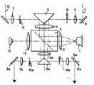
- the only figure shows the - schematic beam path with the essential optical parts.
- (4) denotes the main objective for the image-taking telescope system.
- the divider prism (5) creates a pupil division of the IR bundle. This results in two image planes for the lens (4), in which an image of the detector line or the IR scene is created.
- These intermediate images are imaged by the lenses (6,7) of the optical channels after deflection by the mirrors (8,9) to infinity. Due to the spatial distance between the two optical axes (10) and (11), these intermediate images differ slightly in perspective. If both intermediate images were imaged together on the detector (1), then no spatial image would still arise, since the detector cannot distinguish between the two images.
- lines 1-60 in the right channel and lines 61-120 in the left channel are covered in a 120-line thermal imager, for example. If the two mirrors (8) and (9) are now adjusted so that the two optical axes run exactly parallel, different images of the same IR scene are supplied to the two detector groups in perspective. The IR images are reproduced in such a way that the image of the light-emitting diodes (12) is imaged to infinity via the objective (13) and the scan mirror (3). As in the recording channel, there is now a pupil division in the playback channel according to the lens (4a).
- the halves of the lines are covered so that the left eyepiece (7a) only sees lines 1 to 60 (1 to n), the right eyepiece only lines 61 to 120 (n + 1 to 2n). It also applies here that the two beam paths are adjusted exactly parallel by means of the two mirrors (9a) and (8a). If you look into the two eyepieces, you get the impression of a spatial image.
Landscapes
- Physics & Mathematics (AREA)
- Astronomy & Astrophysics (AREA)
- General Physics & Mathematics (AREA)
- Optics & Photonics (AREA)
- Testing, Inspecting, Measuring Of Stereoscopic Televisions And Televisions (AREA)
- Transforming Light Signals Into Electric Signals (AREA)
- Radiation Pyrometers (AREA)
Abstract
Description
- Die Erfindung betrifft ein stereoskopisches Wärmebildgerät, das aus einem Detektor, einem IR-Objektiv und einem Scannersystem sowie aus je einem binokularen Fernrohrsystem für die Bildaufnahme und Wiedergabe besteht.
- Derartige stereoskopische Wärmebildgeräte sind beispielsweise aus der PCT-Anmeldung Nr. WO 84-03777 bekannt. Bei diesem bekannten stereoskopischen Wärmebildgerät wird die Trennung der beiden optischen Kanäle derart vorgenommen, daß dem Detektor abwechselnd das Bild des rechten und des linken Optikkanals angeboten wird. Die Trennung der beiden Kanäle für die Bildwiedergabe erfolgt in einer Elektronik, die die Signale getrennt weiterverarbeitet.
- Der Erfindung liegt die Aufgabe zugrunde, die Beaufschlagung des Detektors mit den beiden stereoskopischen Halbbildern sowie die Trennung der beiden optischen Kanäle fur die Wiedergabe zu vereinfachen.
- Diese Aufgabe wird erfindungsgemäß dadurch gelöst, daß einer Detektorhälfte das Bild des einen Optikkanals und der anderen Detektorhälfte das Bild des anderen Optikkanals dargeboten wird, und daß die Femrohrsysteme für die Bildaufnahme und Bildwiedergabe ein jeweils beiden Optikkanälen gemeinsames Hauptobjektiv (4,4a) und ein Teilerprisma (5,5a) enthalten und daß im rechten und im linken Optikkanal eines jeden Fernrohrsystems ein weiteres Objektiv (6,7,6a,7a) und mindestens ein Umlenkspiegel (8,9,8a,9a) vorgesehen sind.
- Zur Wiedergabe der IR-Bilder sind zweckmäßigerweise Leuchtdioden vorgesehen, deren Bild über ein vor der Diode angeordnetes Objektiv und einen Scan-Spiegel ins Unendliche abgebildet wird.
- Die mit der Erfindung erzielten Vorteile bestehen insbesondere in der damit möglichen kleinen Bauweise fur ein binokulares Sichtgerät für stereoskopische Betrachtung im IR-Bereich.
- Ein Ausführungsbeispiel der Erfindung ist in der Zeichnung dargestellt und wird im folgenden näher beschrieben. Die einzige Figur zeigt den - schematischen Strahlengang mit den wesentlichen optischen Teilen. In dieser schematischen Darstellung ist mit (4) das Hauptobjektiv für das bildaufnehmende Fernrohrsystem bezeichnet. Das Teilerprisma (5) erzeugt eine Pupillenteilung des IR-Bündels. Daraus resultieren für das Objektiv (4) zwei Bildebenen, in denen eine Abbildung der Detektorzeile bzw. der IR-Szene entsteht. Diese Zwischenbilder werden durch die Objektive (6,7) der Optikkanäle nach Umlenkung durch die Spiegel (8,9) ins Unendliche abgebildet. Bedingt durch den räumlichen Abstand der beiden optischen Achsen (10) und (11) unterscheiden sich diese Zwischenbilder geringfügig in der Perspektive. Wurden beide Zwischenbilder gemeinsam auf dem Detektor (1) abgebildet, so würde trotzdem kein räumliches Bild entstehen, da der Detektor die beiden Bilder nicht unterscheiden kann. Zur Trennung dieser beiden Bilder auf dem Detektor deckt man beispielsweise bei einem 120-zeiligen Wärmebildgerät die Zeilen 1-60 im rechten Kanal und die Zeilen 61-120 im linken Kanal ab. Werden nun die beiden Spiegel (8) und (9) so justiert, daß die beiden optischen Achsen genau parallel verlaufen, so werden den beiden Detektorgruppen perspektivisch unterschiedliche Bilder der gleichen IR-Szene zugeführt. Die Wiedergabe der IR-Bilder erfolgt in der Weise, daß das Bild der Leuchtdioden (12) uber das Objektiv (13) und den Scan-Spiegel (3) ins Unendliche abgebildet wird. Wie im Aufnahmekanal, so erfolgt nun auch im Wiedergabekanal eine Pupillenteilung nach dem Objektiv (4a). In den Zwischenbildebenen werden wiederum die Hälften der Zeilen abgedeckt, so daß das linke Okular (7a) nur die Zeilen 1 bis 60 (1 bis n), das rechte Okular nur die Zeilen 61 bis 120 (n + 1 bis 2n) sieht. Auch hier gilt, daß mittels der beiden Spiegel (9a) und (8a) die beiden Strahlengänge genau parallel justiert werden. Blickt man nun in die beiden Okulare, so entsteht der Eindruck eines räumlichen Bildes.
Claims (3)
Applications Claiming Priority (2)
| Application Number | Priority Date | Filing Date | Title |
|---|---|---|---|
| DE19863629458 DE3629458A1 (de) | 1986-08-29 | 1986-08-29 | Stereoskopisches waermebildgeraet |
| DE3629458 | 1986-08-29 |
Publications (2)
| Publication Number | Publication Date |
|---|---|
| EP0257313A2 true EP0257313A2 (de) | 1988-03-02 |
| EP0257313A3 EP0257313A3 (de) | 1990-05-16 |
Family
ID=6308490
Family Applications (1)
| Application Number | Title | Priority Date | Filing Date |
|---|---|---|---|
| EP87110736A Withdrawn EP0257313A3 (de) | 1986-08-29 | 1987-07-24 | Stereoskopisches Wärmebildgerät |
Country Status (3)
| Country | Link |
|---|---|
| US (1) | US4861997A (de) |
| EP (1) | EP0257313A3 (de) |
| DE (1) | DE3629458A1 (de) |
Cited By (1)
| Publication number | Priority date | Publication date | Assignee | Title |
|---|---|---|---|---|
| WO2010058010A3 (de) * | 2008-11-24 | 2010-07-29 | Carl Zeiss Optronics Gmbh | Stereokameraeinrichtungen, verfahren zur fortlaufenden automatischen kalibrierung einer stereokameraeinrichtung, computerprogramm, computerprogrammprodukt und überwachungsvorrichtung für windkraftanlagen, gebäude mit transparenten bereichen, start- und landebahnen und/oder flugkorridore von flughäfen |
Families Citing this family (3)
| Publication number | Priority date | Publication date | Assignee | Title |
|---|---|---|---|---|
| US5115339A (en) * | 1989-07-03 | 1992-05-19 | Cambridge Instruments Inc. | Stereomicroscope |
| US5689547A (en) * | 1995-11-02 | 1997-11-18 | Ericsson Inc. | Network directory methods and systems for a cellular radiotelephone |
| RU2204856C1 (ru) * | 2002-07-18 | 2003-05-20 | Фроимсон Игорь Михайлович | Сканирующий наблюдательный прибор |
Family Cites Families (5)
| Publication number | Priority date | Publication date | Assignee | Title |
|---|---|---|---|---|
| US3251933A (en) * | 1962-10-31 | 1966-05-17 | Vare Ind Inc | Three-dimensional television system |
| DE6607760U (de) * | 1967-11-08 | 1971-04-15 | Licentia Gmbh | Binokulares sichtgeraet |
| US3670097A (en) * | 1969-10-20 | 1972-06-13 | Nasa | Stereoscopic television system and apparatus |
| US4574197A (en) * | 1983-03-24 | 1986-03-04 | Hughes Aircraft Company | Dual field of view sensor |
| US4601053A (en) * | 1983-11-21 | 1986-07-15 | Grumman Aerospace Corporation | Automatic TV ranging system |
-
1986
- 1986-08-29 DE DE19863629458 patent/DE3629458A1/de not_active Withdrawn
-
1987
- 1987-07-24 EP EP87110736A patent/EP0257313A3/de not_active Withdrawn
- 1987-08-25 US US07/089,068 patent/US4861997A/en not_active Expired - Fee Related
Cited By (1)
| Publication number | Priority date | Publication date | Assignee | Title |
|---|---|---|---|---|
| WO2010058010A3 (de) * | 2008-11-24 | 2010-07-29 | Carl Zeiss Optronics Gmbh | Stereokameraeinrichtungen, verfahren zur fortlaufenden automatischen kalibrierung einer stereokameraeinrichtung, computerprogramm, computerprogrammprodukt und überwachungsvorrichtung für windkraftanlagen, gebäude mit transparenten bereichen, start- und landebahnen und/oder flugkorridore von flughäfen |
Also Published As
| Publication number | Publication date |
|---|---|
| US4861997A (en) | 1989-08-29 |
| DE3629458A1 (de) | 1988-03-03 |
| EP0257313A3 (de) | 1990-05-16 |
Similar Documents
| Publication | Publication Date | Title |
|---|---|---|
| DE10027166B4 (de) | Stereoskopmikroskop | |
| EP0342419B1 (de) | Verfahren zur Beobachtung einer Szene und Einrichtung zur Durchführung des Verfahrens | |
| DE69229778T2 (de) | Objektivlinsensystem für stereo-video-endoskop | |
| DE4212924C2 (de) | Stereomikroskop | |
| DE4114646C2 (de) | Ophthalmoskopie-Vorsatz für ein Operationsmikroskop | |
| DE102012207931A1 (de) | Kameraanordnung zur Distanzmessung | |
| DE102016117024B4 (de) | Vorrichtung zum Erfassen eines Stereobilds sowie Verfahren zum Justieren der Vorrichtung | |
| DE10255961B3 (de) | Stereomikroskop | |
| DE10243852A1 (de) | Mikroskopiesystem und Mikroskopieverfahren | |
| DE102005040473B4 (de) | Stereomikroskop | |
| EP0257313A2 (de) | Stereoskopisches Wärmebildgerät | |
| DE3726144A1 (de) | Operationsmikroskop | |
| DE102008001352A1 (de) | Stereomikroskop mit Strahlteilereinrichtung | |
| DE4340461B4 (de) | Stereoskopische Bildaufnahmevorrichtung | |
| DE4225507C2 (de) | Stereoskopisches Endoskop | |
| DE19532400B4 (de) | Stereoendoskop mit abgewinkelter Blickrichtung | |
| DE102016217784A1 (de) | Kalibriersystem | |
| DE19840972A1 (de) | Stereoskopisches Anzeigesystem | |
| EP0770309B1 (de) | 3d-video-endoskop | |
| DE102015214082A1 (de) | Operationsmikroskop mit Einkoppelmodul und Auskoppelmodul | |
| DE69211822T2 (de) | Anordnung zur Bestimmung desjenigen Teils eines Bildfeldes, das vom Auge eines Beobachters betrachtet wird | |
| WO2005098508A2 (de) | Bildaufnahmesystem, bildwiedergabesystem und bildaufnahme/-wiedergabesystem | |
| DE1957846A1 (de) | Apparat zur stereoskopischen Wiedergabe | |
| DE7227344U (de) | Stereoskop zur betrachtung eines messbildpaares | |
| CH600305A5 (en) | Stereo-evaluator for aerial photographs |
Legal Events
| Date | Code | Title | Description |
|---|---|---|---|
| PUAI | Public reference made under article 153(3) epc to a published international application that has entered the european phase |
Free format text: ORIGINAL CODE: 0009012 |
|
| AK | Designated contracting states |
Kind code of ref document: A2 Designated state(s): AT CH DE FR GB LI NL |
|
| PUAL | Search report despatched |
Free format text: ORIGINAL CODE: 0009013 |
|
| AK | Designated contracting states |
Kind code of ref document: A3 Designated state(s): AT CH DE FR GB LI NL |
|
| 17P | Request for examination filed |
Effective date: 19901112 |
|
| STAA | Information on the status of an ep patent application or granted ep patent |
Free format text: STATUS: THE APPLICATION IS DEEMED TO BE WITHDRAWN |
|
| 18D | Application deemed to be withdrawn |
Effective date: 19920201 |
|
| RIN1 | Information on inventor provided before grant (corrected) |
Inventor name: MARX, DIETER |