EP0257576B1 - Procédé et dispositif pour éviter les défauts causés par la soudure des contacts dans des systèmes de chauffage et de refroidissement - Google Patents
Procédé et dispositif pour éviter les défauts causés par la soudure des contacts dans des systèmes de chauffage et de refroidissement Download PDFInfo
- Publication number
- EP0257576B1 EP0257576B1 EP87112143A EP87112143A EP0257576B1 EP 0257576 B1 EP0257576 B1 EP 0257576B1 EP 87112143 A EP87112143 A EP 87112143A EP 87112143 A EP87112143 A EP 87112143A EP 0257576 B1 EP0257576 B1 EP 0257576B1
- Authority
- EP
- European Patent Office
- Prior art keywords
- compressor
- temperature
- heating
- mode
- switched
- Prior art date
- Legal status (The legal status is an assumption and is not a legal conclusion. Google has not performed a legal analysis and makes no representation as to the accuracy of the status listed.)
- Expired - Lifetime
Links
- 238000010438 heat treatment Methods 0.000 title claims description 38
- 238000001816 cooling Methods 0.000 title claims description 37
- 238000000034 method Methods 0.000 title claims description 29
- 238000003466 welding Methods 0.000 title claims description 24
- 239000003507 refrigerant Substances 0.000 claims description 10
- 238000012544 monitoring process Methods 0.000 claims description 7
- 230000007547 defect Effects 0.000 claims description 6
- 238000012937 correction Methods 0.000 claims description 2
- 239000000523 sample Substances 0.000 claims 2
- 230000002457 bidirectional effect Effects 0.000 abstract 1
- XLYOFNOQVPJJNP-UHFFFAOYSA-N water Substances O XLYOFNOQVPJJNP-UHFFFAOYSA-N 0.000 description 17
- 239000003570 air Substances 0.000 description 12
- 239000007788 liquid Substances 0.000 description 11
- 230000006870 function Effects 0.000 description 6
- 238000003860 storage Methods 0.000 description 6
- 230000003750 conditioning effect Effects 0.000 description 5
- 230000009467 reduction Effects 0.000 description 4
- 238000010257 thawing Methods 0.000 description 4
- 230000008859 change Effects 0.000 description 3
- 238000010586 diagram Methods 0.000 description 3
- 239000004065 semiconductor Substances 0.000 description 3
- 230000009471 action Effects 0.000 description 2
- 230000003213 activating effect Effects 0.000 description 2
- 238000004364 calculation method Methods 0.000 description 2
- 230000006378 damage Effects 0.000 description 2
- 238000004880 explosion Methods 0.000 description 2
- 239000012530 fluid Substances 0.000 description 2
- 230000008569 process Effects 0.000 description 2
- JKIYPXKCQBHOLY-UHFFFAOYSA-N 5-(dimethylamino)-2-(1,3-thiazol-2-yldiazenyl)benzoic acid Chemical compound OC(=O)C1=CC(N(C)C)=CC=C1N=NC1=NC=CS1 JKIYPXKCQBHOLY-UHFFFAOYSA-N 0.000 description 1
- 239000012080 ambient air Substances 0.000 description 1
- 230000004888 barrier function Effects 0.000 description 1
- 239000000872 buffer Substances 0.000 description 1
- 230000001143 conditioned effect Effects 0.000 description 1
- 230000008094 contradictory effect Effects 0.000 description 1
- 239000012809 cooling fluid Substances 0.000 description 1
- 239000000498 cooling water Substances 0.000 description 1
- 230000005611 electricity Effects 0.000 description 1
- 238000005516 engineering process Methods 0.000 description 1
- 238000001704 evaporation Methods 0.000 description 1
- 239000008236 heating water Substances 0.000 description 1
- 238000002955 isolation Methods 0.000 description 1
- 238000004519 manufacturing process Methods 0.000 description 1
- 238000005259 measurement Methods 0.000 description 1
- 230000007246 mechanism Effects 0.000 description 1
- 239000000203 mixture Substances 0.000 description 1
- 230000003287 optical effect Effects 0.000 description 1
- 230000000737 periodic effect Effects 0.000 description 1
- 230000002093 peripheral effect Effects 0.000 description 1
- 239000007858 starting material Substances 0.000 description 1
- 239000008399 tap water Substances 0.000 description 1
- 235000020679 tap water Nutrition 0.000 description 1
- 238000012360 testing method Methods 0.000 description 1
- 230000036962 time dependent Effects 0.000 description 1
Images

Classifications
-
- F—MECHANICAL ENGINEERING; LIGHTING; HEATING; WEAPONS; BLASTING
- F25—REFRIGERATION OR COOLING; COMBINED HEATING AND REFRIGERATION SYSTEMS; HEAT PUMP SYSTEMS; MANUFACTURE OR STORAGE OF ICE; LIQUEFACTION SOLIDIFICATION OF GASES
- F25B—REFRIGERATION MACHINES, PLANTS OR SYSTEMS; COMBINED HEATING AND REFRIGERATION SYSTEMS; HEAT PUMP SYSTEMS
- F25B49/00—Arrangement or mounting of control or safety devices
- F25B49/005—Arrangement or mounting of control or safety devices of safety devices
-
- F—MECHANICAL ENGINEERING; LIGHTING; HEATING; WEAPONS; BLASTING
- F25—REFRIGERATION OR COOLING; COMBINED HEATING AND REFRIGERATION SYSTEMS; HEAT PUMP SYSTEMS; MANUFACTURE OR STORAGE OF ICE; LIQUEFACTION SOLIDIFICATION OF GASES
- F25B—REFRIGERATION MACHINES, PLANTS OR SYSTEMS; COMBINED HEATING AND REFRIGERATION SYSTEMS; HEAT PUMP SYSTEMS
- F25B13/00—Compression machines, plants or systems, with reversible cycle
-
- H—ELECTRICITY
- H01—ELECTRIC ELEMENTS
- H01H—ELECTRIC SWITCHES; RELAYS; SELECTORS; EMERGENCY PROTECTIVE DEVICES
- H01H3/00—Mechanisms for operating contacts
- H01H3/001—Means for preventing or breaking contact-welding
Definitions
- the invention is in the field of security technology and relates to a method and a device according to the preambles of claims 1 and 8.
- this control device In all systems that use a compressor to compress a refrigerant, there is a control device for switching the compressor on and off at certain times. In its simplest versions, this control device can essentially only contain one thermostat and one relay or, in more sophisticated systems, multiple relays or, more recently, programmable microcomputers. Regardless of the complexity of the system, however, electromagnetic or electronic relays or semiconductor switches are used to switch the power supply from the power supply to the compressor on and off.
- Another variant of such a safety device uses an interruption switch which interrupts all current paths of the compressor motor as soon as very high pressures, temperatures or currents occur. While this type of device is effective, it is very expensive, increasing the overall cost of the system in which it is used.
- the invention thus relates to a method for monitoring a heating and cooling system with a compressor and a changeover valve, certain system parameters being monitored during normal operation of the system in order to be able to determine the conditions for switching off the compressor.
- the compressor is monitored to determine whether it has not yet switched off when these conditions occur, which suggests a contact welding error and initiates a safety operating mode if such a contact welding error is present.
- This safety operating mode includes a periodic switching of the state of the switching valve, whereby the system between a heating and Cooling mode is switched so that the compressor is permanently loaded until a manual correction is made.
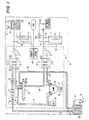
- FIG. 1 which corresponds to FIG. 1 of the above-mentioned patent, an air pipe coil 10 lying outside the system can be seen with a fan 11 which directs the outside air into and through the pipe coil.
- This coil 10 is a conventional air-cooled heat exchanger as it is manufactured by various companies in the HVAC sector. In the system shown, this heat exchanger is arranged locally and thermodynamically in the usual way.
- the arrangement which is to be heated and cooled by means of the system is indicated by a dash-dotted line 12 which schematically delimits this arrangement.
- One connection of the pipe coil 10 is connected to a pipe 13 which leads into this arrangement and into a module referred to below as the generator module 14, all elements of this module in the present system being in a single housing.
- the tube 13 is connected to a conventional thermostatic control valve 16.
- the control valve is followed by a filter drier 17, a collecting vessel 18 and the connection of the cooling side of a water-cooled heat exchanger HX-1 in the following order.
- the other connection on the cooling side of the heat exchanger HX-1 is connected via a line 19 to a conventional 4-way switch valve 20, which is only shown schematically here, and which can have two states.
- This valve 20 is preferably a solenoid actuated and software controlled valve according to the above-mentioned patent.
- the valve 20 is shown in the state of the cooling mode, in which the line 19 is connected via the valve to a line 21 which leads to a pressure accumulator 22, the other side of which leads to the suction side of a conventional compressor 24.
- the compressor is in the usual way with a crankcase heater 26 Mistake.
- the output of the compressor 24 is connected by means of a line 27 to the cooling side of a water-cooled heat exchanger HX-2, the other connection of which is connected to the changeover valve 20 via a line 29.
- the line 29 is connected to a line 30 which leads back to the second connection of the outside air pipe coil.
- the line 29 is connected to the line 19 and the line 21 to the line 30 in the heating mode.
- the water circuit which is connected to the water connection side of the heat exchanger HX-1 contains, in series, a pump P1, an interior pipe coil 32 and a cooling or heating water storage tank S1, these elements being connected to one another by corresponding lines.
- the indoor coil 32 is provided with a fan or blower 34 which directs the air through the heat exchanger 32 and over its coils, thereby causing a sufficient heat exchange between the water and the air and conditioning the interior.
- the water circuit side of the heat exchanger HX-2 contains a pump P2, which connects to this and leads the supplied water via the water circuit side of the heat exchanger HX-2 into the lowest area of an associated hot water storage tank S2.
- the other side of the water coil of the heat exchanger HX-2 is connected to an ordinary water pipe connection and a pipe 36 which leads to the bottom of the tank S2.
- a hot water overflow 37 At the upper end of the container S2 there is a hot water overflow 37, which is connected to the hot water supply line 39 via a mixing valve 38.
- the line 36 is also connected to the starter valve, so that the required mixture between hot and tap water is carried out by means of the valve and hot water with the desired temperature is available at the outlet.
- the tanks S1 and S2 also have, as shown schematically in FIG. 1, resistance heating elements 40, 42, so that, under appropriate conditions, additional energy can be supplied to the system in order to heat the water in one or both tanks.
- the heating element 40 preferably has two heating elements connected in parallel.
- the heat exchanger HX-2 is arranged at the outlet or the pressure side of the compressor 24, so that it can be supplied at any time with the refrigerant brought to a higher temperature in order to close the water in the tank S2 during the heating or cooling mode heat or, if desired, heat or cool when the system is out of operation.
- the tanks S1 and S2 are preferably 0.454m3 (120 gallons) hot water tanks, the tank S1 being provided with two 4.5 kW heating elements and the tank S2 being provided with a 4.5 kW heating element.
- the control software of this system controls the compressor, the pumps and fans so that the storage tank is brought to the desired temperature outside of the peak power consumption times, ie the liquid contained therein is heated or cooled depending on the position of a switch on the control console 44.
- the system enables the environment to be heated or cooled during peak times, with the compressor on time being minimized during these peak times.
- the software can, for example be contained in a device controller 45, which are connected to the various elements of the system, including the control console 44 and a plurality of temperature sensors, which are shown in FIG. 1 by circled capital letters. These sensors are of great importance for the various control mechanisms made possible by the system.
- the sensor C for measuring the outlet temperature of the compressor 24 (t_dis); sensor B for measuring the temperature of the liquid distributor of the outside air coil 10 (t_liq), which represents the evaporating temperature during the heating mode and the outflow temperature of the liquid during the cooling mode; and the sensor G, which measures the temperature of the ambient air (t_amb) at the input of the heat exchanger 10.
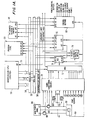
- FIG. 1A shows a functional block diagram of the device of the system according to FIG. 1, the functional blocks which form the device controller 45 and the sensors being shown in somewhat more detail and illustrating the relationship between the software parts contained therein.
- the microprocessor subsystem 50 is bidirectionally connected to the data bus 52 and has outputs to an address bus 54 and a microprocessor control bus 56.
- the subsystem 50 also contains interrupt inputs via the line 58.
- a program memory 60 for example a disk drive with a Disk drive controller is provided so that the program for controlling the system can be stored on a hard disk or floppy disk or the program is stored in a corresponding chip, for example a ROM.
- the program memory receives data, addresses, microprocessor control and input-output control input signals and provides data and interrupt output signals.
- An I / O address, decode and monitor unit 64 also receives address, data and microprocessor control input signals and provides data and I / O control signals.
- the system signal inputs are connected to sensors that indicate the energy supplied to the space conditioned by the system, as well as to temperature sensors A, B, C, D, F, G, and H that measure the temperature at different locations in the system. These sensors are described in somewhat more detail in connection with Figures 1 and 5 of U.S. Patent 4,645,908.
- the energy is measured by means of current sensors 88 and 89 and voltage measuring transformers 103 and 104, which are coupled to the main supply lines, for example from the main supply switchboard 66, which are connected to the supply and the main measuring instrument 68, which measures the energy supplied to the arrangement for billing purposes , connected is.
- a signal 69 from this measuring instrument indicates when the measured values are high during an "on peak" interval.
- signal conditioning circuitry 70 which converts the signals into a desired, analog form (except for the main meter signal, which is digital) and adjusts them to an appropriate amplitude.
- the outputs of the signal conditioning circuit 70 are fed to an analog multiplexer circuit 72, the signal outputs of which lead to an analog / digital converter circuit 74.
- a universal control logic unit 76 is also provided with the I / O control lines, address lines, the data bus and the microprocessor control bus connected in order to be able to fulfill various monitoring functions.
- This unit receives and delivers peripheral, local control signals (LPC) from or to a discrete, digital input unit 78 and a control output unit 80.
- LPC peripheral, local control signals
- the control output unit 80 provides supply control values for various measuring devices and valves, including the outside air fan 11, the four-way switch valve 20, the compressor 24, the indoor fan 34, the heating elements 40 and 42, and the pumps P1 and P2 . They control both the digital interface and the optical isolation (e.g. optocoupler), the relay coil drive and the power control relay.
- various measuring devices and valves including the outside air fan 11, the four-way switch valve 20, the compressor 24, the indoor fan 34, the heating elements 40 and 42, and the pumps P1 and P2 . They control both the digital interface and the optical isolation (e.g. optocoupler), the relay coil drive and the power control relay.
- control output unit 80 and the program memory 60, which interact with the microprocessor subsystem 50 and the universal control logic unit 76.
- the control output unit 80 contains the electronic - or other relays which control the compressor and therefore contain the "contacts", be they semiconductors or others, which must be monitored by the program. Likewise, sensors B, C and G are monitored as mentioned above.
- the microprocessor subsystem which contains the microprocessor and the microcontroller, ROM, RAM, system clock and the time circuit, the interrupt controller, the system control circuit, and the address data and control buffers carry out the current process, with the program in the program storage unit 60 is stored.
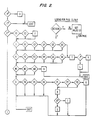
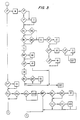
- FIGS. 2 to 4 show a simplified flowchart of a program for executing the method, which determines whether a safety mode should be initialized, thereby indicating the existence of a contact welding error.
- switching to safety mode means that normal operating conditions are disregarded and the system is controlled in such a way that the conditions causing this safety mode can be taken into account.
- the procedure is explained in more detail using a program written in the C programming language and the printout of which is given in Appendix I.
- the method consists in monitoring certain parameters of the system during operation in order to be able to determine whether conditions occur which indicate the occurrence of a contact weld. For this purpose, three temperatures are measured, which serve to determine whether such a system condition exists. If the temperatures are as expected under normal operating conditions, no safety measure is taken. If, on the other hand, conditions are determined which should not occur, a safety mode for "saving the compressor" is initialized.
- the conditions for switching between normal operation and safety mode are briefly outlined below.
- the individual modules which are part of the control software for the system in Figure 1, are arranged so that their functions are essentially independent of each other. Each module fulfills its own task and generates a corresponding output after a certain time, ie periodically. Regardless of whether this output is required or is ignored, the module performs its function again in the following period.
- the output can consist of a calculation result that is used in other modules or a trigger signal for a specific action. This action can consist, for example, of activating a hardware element or triggering security mode.
- the modules do not send an execution command themselves, but only report a corresponding request signal. It is quite possible that several modules want to activate a certain element of the device at the same time. In addition, it can e.g. it can happen that two modules send contradicting signals at the same time, which can have different reasons. For example, it is possible for one module to determine an internal temperature, which should actually result in the compressor being switched on so that it cools the room, but another module for determining that the room can be adequately cooled from the storage tank S1 using cold water and the compressor should not be switched on because a high electricity tariff applies at this time of day.
- REDUCTION determines and filters out the one to be taken into account in the case of a plurality of signals.
- a switch-off signal usually has higher priority than a switch-on signal and request signals for activating the safety mode are taken into account first, since they indicate potential dangerous situations.
- SEQUENCER The module receives the filtered output signal of the REDUCTION module and sends the current signal, which switches the corresponding hardware elements on or off, according to a defined priority order. Since the present program ensures that the safety mode is switched on when the corresponding conditions occur, its output is recognized by the REDUCTION and SEQUENCER module and processed within the same or the following period in such a way that the safety mode is switched over.
- the three temperatures to be measured already mentioned above i.e. the initial temperature at the compressor (t_dis), the external ambient temperature (t_amb) and the temperature of the liquid refrigerant in the outside air pipe coil (t_liq) are identified with capital letters, for example as TLIQ, TDIS, TAMB, if they are to bring about changes in the system .
- the calculation or measurement period is e.g. Four seconds and the various system temperatures are accordingly fed to these modules on a regular basis.
- various values such as the upper and lower values of t_liq of the last 16 periods and the average temperature TLIQ are calculated and / or saved.
- the occurrence of certain events or certain signals is recorded and logged, e.g. switching the compressor on and off or changing the status of the changeover valve.
- the first step is to determine whether the time period since the start of the overall system is less than 8 seconds (A * ). If this is the case, this indicates that the system is in the special state of the start phase. It can be accepted that no contact welds occur and no safety precautions need to be taken (B).
- the software is aligned with regard to three different time phases. During normal operation, the cycles last approximately 4 seconds each. During the start-up, two different types of phases can be distinguished, which are also treated differently. The first, which lasts approximately 4 to 8 seconds, is called phase 1 and is followed by the so-called initialization phases. A sequence of such initialization phases follows this phase 1 for a period of approximately five minutes during which additional further system initialization procedures take place. If it is determined that the system is in an initialization phase (E1) and less than 12 seconds (E2) have passed since the restart, it is necessary to determine some initialization values for the execution of the program.
- E1 initialization phase
- E2 12 seconds
- the output temperature of the compressor is set equal to the current output temperature and t_liq to the current liquid temperature (F).
- pumps P1 and P2 are switched on by means of request signals from the system and the switchover valve is deactivated, so that the valve is switched to heating or cooling mode.
- the switch valve mode will open Zero and the timeout flag set to zero.
- the time-out flag is used to check the time to ensure that the system has not overlooked or passed over any dangerous situation. An interval of 10 minutes after switching off the compressor is decisive. If the initial temperature is less than 43.4 ° C (110 ° F) after this interval, it can be assumed that something has been overlooked. This will be determined at a later date.
- a safety flag is set.
- a set of conditions that enable this flag assumes the system is in cooling mode (G1-G6).
- the program checks whether, TDIS is greater than 60.0 ° C (140 ° F) (all temperatures are given here in ° Celsius (Fahrenheit)); whether TDIS is at least as high as the measured start temperature t_dis minus 5.6 ° C (10 ° F); whether TLIQ is at least 11.2 ° C (20 ° F) lower than the ambient temperature and also at least as high as the start temperature t_dis minus 5.6 ° C (10 ° F); and whether the ambient temperature is above 10 ° C (50 ° F). If all of these conditions are met, a flag is set (I) as this indicates a serious danger to the compressor.
- the system is in heating mode (H1-H6); TDIS is greater than 60.0 ° C (140 ° F) and greater than t_dis at startup minus 5.6 ° C (10 ° F) and TLIQ is at an ambient temperature of 50 ° or less, less than 8.4 ° C (15 ° F) below the ambient temperature and less than 2.8 ° C (5 ° F) under t_liq when starting up, this indicates a danger to the compressor and the safety flag is set (I, J *, K, L) .
- the program then checks the conditions in order to delete registers that still contain switch-on or switch-off data. If more than 4 minutes have passed since the start-up and TDIS is less than 54.5 ° C (130 ° F) (M1, M2, M3), the compressor is either not connected or there is insufficient refrigerant in the system. In both cases, it is not necessary to set a safety flag, so that both the register for the switch-on signal and the register for the switch-off signal intended to avoid contact welding errors are set to zero (Qa, Qb).
- a crisis entry flag is set to TRUE and the safety mode is switched on depending on the position of the switch on the HOC 44 control panel to protect the compressor in heating as in cooling mode (R, S *, T, U).
- the program sets a request signal for switching on the pump P1 if the system is in the normal operating phase, has been switched on for more than 7 minutes and 4 seconds and if the compressor is switched on (V *, W). If less than 5 minutes have passed since the last request signal for a status change of the compressor or the changeover valve, the upper and lower liquid temperature are stored in the system according to the temperature TLIQ at this time (X *, Y *, Za, Zb). If the cooling mode is set on the HOC control console or if there is a request signal for switching off the cooling mode (AA1, AA2, BB1, BB2), the program delivers a request signal for switching on the changeover valve (CC). If the stored upper liquid temperature is below the current value of TLIQ, the upper temperature t_liq is set to this current value (DD *, EE).
- the changeover valve is set to cooling accordingly (FF *, GG).
- the upper temperature TLIQ is set to the calculated average temperature TLIQ (HH *, II). In other words, the former is reset every 15 minutes during the operation of the compressor.
- the cooling switch since it is possible that the cooling switch is switched so that the changeover valve is in heating mode, it should be switched to defrost (JJ, KK). Otherwise the changeover valve must be switched off. Logic must be used here to ensure that any data bit that would require the switching valve to be switched off is deleted. The corresponding data word requiring switching off is therefore masked in order to remove this bit.
- the lower temperature t_liq is set to TLIQ (MM *, NN).
- the changeover valve is switched to recuperation mode (OO *, PP). Otherwise, the program branches to heating or "valve off” mode as standard and the changeover valve mode is set to "heating" (QQ). If more than 30 minutes have passed since the last change of valve position and the compressor has been switched on for a time period that corresponds to an integer multiple of 15 minutes, the lower value of t_liq is set to the average value TLIQ (RR1, RR2, SS ).
- the compressor To go to the next program section, the compressor must be switched off, ie it must have received a switch-off signal generated by the SEQUENCER (ie the FALSE output value of V * ).
- the routine checks when the compressor has been switched off. If the time period since switching off is less than two time periods, the time barrier flag is deleted (false) and the temperature t_dis is estimated at the current value of TDIS, or assumed at this value (TT * , UU).
- the changeover valve is in heating mode (WW * )
- the compressor output temperature is higher than the temperature t_dis at the time of switching off minus 5.6 ° C (10 ° F) and if TLIQ is more than 2.8 ° C (5 ° F) below the lower temperature t_liq
- the contact welding safety mode is switched on and the crisis entry flag is set to TRUE (XX1, XX2, YY). If the output temperature has dropped by 5.6 ° C (10 ° F) or more and if the liquid temperature is higher than the lower temperature t-liq, the safety mode is not activated (ZZ1, ZZ2, AAA).
- the contact welding safety mode is switched on and the crisis entry flag is set to TRUE, provided the changeover valve is in cooling mode (BBB * ), the compressor output temperature is above the temperature t_dis at the switch-off time minus 5.6 ° C (10 ° F ) and if TLIQ is at least 2.8 ° C (5 ° F) above the higher temperature t_liq (CC1, CC2, DDD). If the output temperature has dropped 5.6 ° C (10 ° F) or more and if the liquid temperature is below the upper temperature t-liq, no safety mode is set (EE1, EE2, FFF).
- the compressor outlet temperature is 1.1 ° C (2 ° F) or more than the temperature t_dis when switched off, the liquid temperature 5.6 ° C (10 ° F) or
- the safety mode is activated (HHH1-3, III) more than the stored value of the upper temperature t_liq and if t_liq is greater than 7.2 ° C (45 ° F). If the output temperature is at least 20 ° below the switch-off temperature, no safety mode is set (YYY * , KKK).
- TDIS is above the switch-off temperature minus 5.6 ° C (10 ° F)
- TLIQ is more than 8.4 ° C (15 ° F) below that saved lower temperature and if more than 5 minutes have passed since the compressor status changed
- the safety mode is set (MMM1-3, NNN).
- the safety mode is not set (000 *, PPP).
- the compressor and the changeover valve are brought into an operating mode in which the valve position is switched over at regular intervals.
- This is a normal, time-dependent switching function, which ensures that the compressor remains permanently loaded and therefore no extreme temperatures and pressure conditions can occur, which could lead to self-destruction of the compressor.
- the changeover valve is continuously switched over until the system is switched off manually.
- the program for the "compressor rescue" routine follows on from the "contact welding protection” routine. Because of the brevity and simplicity of this routine, no flowchart is provided.
- the main purpose of this "compressor rescue” routine is to recognize the crisis entry flag and control the system so that the compressor remains permanently loaded. In the present system, a load is maintained by alternately heating and cooling the space schematically delimited by line 12. This could also be done by alternately heating and cooling the storage tank S1 or, in another system, also by means of other loads. It will have been found that the printed program is designed for the conditioning of the memory and has been written with this in mind. The corresponding terms have been modified to refer to airspace.
- the crisis entry flag and the security flag are checked in the SEQUENCER module described above. If the flag is set, this routine is implemented. If the flag is set to "1", the system is placed in a "room conditioning" mode, i.e. either heated or cooled. First of all, this routine checks the state of the system. The heating mode is assumed as standard; the "contact welding safety” routine then checks whether there is defrosting or heating. The reason for this is that you first want to bring the system into the opposite state to the state immediately preceding it. If the system was in defrost mode, the coil must continue to be defrosted by adding energy to the coil. If the system was in heating mode, the storage tank and airspace were probably hot, so cooling should begin.
- the next program instruction containing a condition sets the device contacts. If the system is put in cooling mode all elements, including pumps P1 and P2, the outside fan, the changeover valve and the inside fan, are switched to cooling. It should be noted that the compressor does not have to be activated since it is either already switched on, which is the reason for executing this routine, or there is an error otherwise. In both cases, it is not desirable for the compressor to be activated.
- the program section initiated by "else" corresponds to the heating mode.
- Certain cooling and heating limits are set for this routine. The following part of the routine checks whether these limits have been exceeded in one direction or the other. If the temperature TRETA of the return air is equal to or lower than the value set on the HOC control panel minus 2.8 ° C (5 ° F) or if it is below 18.3 ° C (65 ° F), switched the heating mode and switched the device contacts accordingly. Similarly, starting from heating mode, the air is only heated to 25.6 ° C (78 ° F) or 2.8 ° C (5 ° F) above the HOC control panel value, whichever is the lower.
- a digital output word is formed by building up "high byte” and “low byte” segments. Each word is 16 bits long and is captured as part of the digital system output.
- the crisis entry flag is then set to 2. It should be noted that the system will not return to the "contact welding safety mode” routine until after a complete system reset once it has run through the "compressor rescue” routine.
Landscapes
- Engineering & Computer Science (AREA)
- Physics & Mathematics (AREA)
- Mechanical Engineering (AREA)
- Thermal Sciences (AREA)
- General Engineering & Computer Science (AREA)
- Compression-Type Refrigeration Machines With Reversible Cycles (AREA)
- Manufacture Of Switches (AREA)
- Devices That Are Associated With Refrigeration Equipment (AREA)
- Control Of Positive-Displacement Pumps (AREA)
- Arc Welding In General (AREA)
- Heat Treatments In General, Especially Conveying And Cooling (AREA)
- Control Of Heat Treatment Processes (AREA)
- Air Conditioning Control Device (AREA)
Claims (11)
- Procédé pour surveiller et commander des systèmes de chauffage et de refroidissement comportant un compresseur et au moins un échangeur de chaleur entre lesquels circule un fluide caloporteur, procédé caractérisé par les étapes suivantes :
a) on surveille au moins un paramètre spécifique du système en cours de fonctionnement pour déterminer des états pour lesquels le compresseur devrait être coupé etb) on constate après émission d'un ordre de coupure, si le compresseur ne s'est pas arrêté dans les conditions correspondantes pour indiquer un incident entraîné par un défaut de soudure de contact etc) on initialise un module de fonctionnement de sécurité en réaction à la constatation d'un tel défaut de soudure de contact, ce module de fonctionnement de sécurité faisant que le compresseur reste chargé pour être protégé contre son autodestruction, jusqu'à la mise en oeuvre d'un moyen de correction. - Procédé selon la revendication 1, caractérisé en ce qu'au moins l'un des paramètres est la température de sortie du compresseur.
- Procédé selon la revendication 1 ou 2, caractérisé en ce qu'au moins l'un des paramètres est la température du fluide caloporteur d'un échangeur de chaleur du système.
- Procédé selon l'une des revendications précédentes, caractérisé en ce que le module de fonctionnement de sécurité commute une soupape d'inversion prévue dans le système, en permanence entre différents états pour que le compresseur soit chargé en permanence.
- Procédé selon l'une des revendications précédentes, caractérisé en ce qu'on charge le compresseur en commutant le système, respectivement à des intervalles déterminés en le faisant passer d'un module de chauffage à un module de refroidissement.
- Procédé selon l'une des revendications précédentes, caractérisé en ce que pour déterminer que le compresseur n'a pas encore été coupé on mesure l'échange d'énergie permanente du fluide caloporteur.
- Procédé selon l'une des revendications précédentes, caractérisé en ce que pour déterminer si le compresseur n'a pas encore été coupé on mesure l'énergie évacuée et/ou fournie par le fluide caloporteur.
- Dispositif pour surveiller et commander un système de chauffage et de refroidissement comportant un compresseur et au moins un échangeur de chaleur entre lesquels circule un fluide caloporteur, caractérisé en ce que :
a) le dispositif comporte des capteurs pour surveiller au moins un paramètre spécifique du système en fonctionnement, pour déterminer des circonstances pour lesquelles il faudrait couper le compresseur du système.b) un module de calcul qui, après émission d'un ordre de coupure, détermine si le compresseur n'a pas été coupé dans ces conditions déterminées, et dans ce cas on affiche un défaut de soudure de contact etc) des éléments de charge et de commande, les premiers étant initialisés par ce module de commande et le module de calcul ou un module de calcul supplémentaire sous la commande d'un module de fonctionnement de sécurité en présence d'un défaut de soudage de contact, la commande étant telle que le compresseur reste en charge pour éviter toute autodestruction du compresseur jusqu'à ce que des mesures de correction soient entreprises. - Dispositif selon la revendication 8, caractérisé en ce que les capteurs comportent un capteur de température pour mesurer la température de sortie du compresseur.
- Dispositif selon l'une des revendications 8 ou 9, caractérisé en ce que les capteurs comportent un capteur de température pour mesurer la température du fluide caloporteur dans un échangeur de chaleur du système.
- Dispositif selon l'une des revendications 8 à 10, caractérisé en ce que les moyens de commande sont constitués par une soupape d'inversion qui est constamment commutée entre les différents états pour le module de fonctionnement de sécurité pour que le compresseur reste chargé en permanence.
Priority Applications (1)
| Application Number | Priority Date | Filing Date | Title |
|---|---|---|---|
| AT87112143T ATE69102T1 (de) | 1986-08-26 | 1987-08-21 | Verfahren und vorrichtung zur vermeidung von durch kontaktschweissungen verursachten defekten in heiz- bzw. kuehlsystemen. |
Applications Claiming Priority (2)
| Application Number | Priority Date | Filing Date | Title |
|---|---|---|---|
| US900586 | 1986-08-26 | ||
| US06/900,586 US4698978A (en) | 1986-08-26 | 1986-08-26 | Welded contact safety technique |
Publications (3)
| Publication Number | Publication Date |
|---|---|
| EP0257576A2 EP0257576A2 (fr) | 1988-03-02 |
| EP0257576A3 EP0257576A3 (en) | 1989-11-02 |
| EP0257576B1 true EP0257576B1 (fr) | 1991-10-30 |
Family
ID=25412757
Family Applications (1)
| Application Number | Title | Priority Date | Filing Date |
|---|---|---|---|
| EP87112143A Expired - Lifetime EP0257576B1 (fr) | 1986-08-26 | 1987-08-21 | Procédé et dispositif pour éviter les défauts causés par la soudure des contacts dans des systèmes de chauffage et de refroidissement |
Country Status (10)
| Country | Link |
|---|---|
| US (1) | US4698978A (fr) |
| EP (1) | EP0257576B1 (fr) |
| JP (1) | JPH01500687A (fr) |
| AT (1) | ATE69102T1 (fr) |
| AU (1) | AU603607B2 (fr) |
| CA (1) | CA1281394C (fr) |
| DE (1) | DE3774211D1 (fr) |
| IE (1) | IE65173B1 (fr) |
| IL (1) | IL83352A (fr) |
| WO (1) | WO1988001716A1 (fr) |
Families Citing this family (30)
| Publication number | Priority date | Publication date | Assignee | Title |
|---|---|---|---|---|
| SE464667B (sv) * | 1988-08-22 | 1991-05-27 | Thermia Ab | Vaermepumpanlaeggning foer uppvaermning eller kylning av utrymmen samt uppvaermning av tappvarmvatten |
| JP2801629B2 (ja) * | 1989-03-29 | 1998-09-21 | 東芝エー・ブイ・イー株式会社 | 空気調和装置 |
| US5105629A (en) * | 1991-02-28 | 1992-04-21 | Parris Jesse W | Heat pump system |
| US5363669A (en) * | 1992-11-18 | 1994-11-15 | Whirlpool Corporation | Defrost cycle controller |
| WO2005065355A2 (fr) | 2003-12-30 | 2005-07-21 | Copeland Corporation | Systeme de diagnostic et de protection de compresseur |
| US7412842B2 (en) | 2004-04-27 | 2008-08-19 | Emerson Climate Technologies, Inc. | Compressor diagnostic and protection system |
| US7275377B2 (en) | 2004-08-11 | 2007-10-02 | Lawrence Kates | Method and apparatus for monitoring refrigerant-cycle systems |
| US8590325B2 (en) | 2006-07-19 | 2013-11-26 | Emerson Climate Technologies, Inc. | Protection and diagnostic module for a refrigeration system |
| US20080216494A1 (en) | 2006-09-07 | 2008-09-11 | Pham Hung M | Compressor data module |
| US20090037142A1 (en) | 2007-07-30 | 2009-02-05 | Lawrence Kates | Portable method and apparatus for monitoring refrigerant-cycle systems |
| US8393169B2 (en) | 2007-09-19 | 2013-03-12 | Emerson Climate Technologies, Inc. | Refrigeration monitoring system and method |
| DE102007052532B4 (de) * | 2007-11-01 | 2012-03-22 | Gordon Seiptius | Sicherheitssystem zur Sicherung von Verdichtern in Kälteanlagen |
| US9140728B2 (en) | 2007-11-02 | 2015-09-22 | Emerson Climate Technologies, Inc. | Compressor sensor module |
| US8160827B2 (en) | 2007-11-02 | 2012-04-17 | Emerson Climate Technologies, Inc. | Compressor sensor module |
| CA2828740C (fr) | 2011-02-28 | 2016-07-05 | Emerson Electric Co. | Solutions de controle et de diagnostic d'un systeme hvac destinees a des habitations |
| US8964338B2 (en) | 2012-01-11 | 2015-02-24 | Emerson Climate Technologies, Inc. | System and method for compressor motor protection |
| US9480177B2 (en) | 2012-07-27 | 2016-10-25 | Emerson Climate Technologies, Inc. | Compressor protection module |
| US9310439B2 (en) | 2012-09-25 | 2016-04-12 | Emerson Climate Technologies, Inc. | Compressor having a control and diagnostic module |
| CA2904734C (fr) | 2013-03-15 | 2018-01-02 | Emerson Electric Co. | Diagnostic et systeme de telesurveillance de chauffage, de ventilation et de climatisation |
| US9803902B2 (en) | 2013-03-15 | 2017-10-31 | Emerson Climate Technologies, Inc. | System for refrigerant charge verification using two condenser coil temperatures |
| US9551504B2 (en) | 2013-03-15 | 2017-01-24 | Emerson Electric Co. | HVAC system remote monitoring and diagnosis |
| AU2014248049B2 (en) | 2013-04-05 | 2018-06-07 | Emerson Climate Technologies, Inc. | Heat-pump system with refrigerant charge diagnostics |
| US10119738B2 (en) | 2014-09-26 | 2018-11-06 | Waterfurnace International Inc. | Air conditioning system with vapor injection compressor |
| US10871314B2 (en) | 2016-07-08 | 2020-12-22 | Climate Master, Inc. | Heat pump and water heater |
| US10866002B2 (en) | 2016-11-09 | 2020-12-15 | Climate Master, Inc. | Hybrid heat pump with improved dehumidification |
| US11879673B2 (en) * | 2018-07-17 | 2024-01-23 | United Electric Company. L.P. | Refrigerant charge control system for heat pump systems |
| US11592215B2 (en) | 2018-08-29 | 2023-02-28 | Waterfurnace International, Inc. | Integrated demand water heating using a capacity modulated heat pump with desuperheater |
| CA3081986A1 (fr) | 2019-07-15 | 2021-01-15 | Climate Master, Inc. | Systeme de conditionnement d`air a regulation de puissance et production d`eau chaude controlee |
| US12181189B2 (en) | 2021-11-10 | 2024-12-31 | Climate Master, Inc. | Ceiling-mountable heat pump system |
| US20250230958A1 (en) * | 2024-01-16 | 2025-07-17 | Haier Us Appliance Solutions, Inc. | Reversing valve with integrated heat exchanger and bypass |
Family Cites Families (8)
| Publication number | Priority date | Publication date | Assignee | Title |
|---|---|---|---|---|
| US4246763A (en) * | 1978-10-24 | 1981-01-27 | Honeywell Inc. | Heat pump system compressor fault detector |
| US4211089A (en) * | 1978-11-27 | 1980-07-08 | Honeywell Inc. | Heat pump wrong operational mode detector and control system |
| JPS55164793A (en) * | 1979-06-07 | 1980-12-22 | Toyoda Autom Loom Works Ltd | Protecting device for refrigerant compressor |
| US4253130A (en) * | 1979-06-08 | 1981-02-24 | Robertshaw Controls Company | Method and apparatus for heat pump system protection |
| US4307775A (en) * | 1979-11-19 | 1981-12-29 | The Trane Company | Current monitoring control for electrically powered devices |
| US4301660A (en) * | 1980-02-11 | 1981-11-24 | Honeywell Inc. | Heat pump system compressor fault detector |
| US4333316A (en) * | 1980-10-14 | 1982-06-08 | General Electric Company | Automatic control apparatus for a heat pump system |
| US4381549A (en) * | 1980-10-14 | 1983-04-26 | Trane Cac, Inc. | Automatic fault diagnostic apparatus for a heat pump air conditioning system |
-
1986
- 1986-08-26 US US06/900,586 patent/US4698978A/en not_active Expired - Fee Related
-
1987
- 1987-07-27 IL IL83352A patent/IL83352A/xx not_active IP Right Cessation
- 1987-08-04 CA CA000543719A patent/CA1281394C/fr not_active Expired - Lifetime
- 1987-08-13 IE IE216487A patent/IE65173B1/en not_active IP Right Cessation
- 1987-08-21 AT AT87112143T patent/ATE69102T1/de not_active IP Right Cessation
- 1987-08-21 DE DE8787112143T patent/DE3774211D1/de not_active Expired - Fee Related
- 1987-08-21 EP EP87112143A patent/EP0257576B1/fr not_active Expired - Lifetime
- 1987-08-25 AU AU78769/87A patent/AU603607B2/en not_active Ceased
- 1987-08-25 JP JP62505480A patent/JPH01500687A/ja active Pending
- 1987-08-25 WO PCT/US1987/002134 patent/WO1988001716A1/fr not_active Ceased
Also Published As
| Publication number | Publication date |
|---|---|
| IE65173B1 (en) | 1995-10-04 |
| DE3774211D1 (de) | 1991-12-05 |
| IE872164L (en) | 1988-02-26 |
| CA1281394C (fr) | 1991-03-12 |
| JPH01500687A (ja) | 1989-03-09 |
| IL83352A (en) | 1992-07-15 |
| WO1988001716A1 (fr) | 1988-03-10 |
| AU603607B2 (en) | 1990-11-22 |
| IL83352A0 (en) | 1987-12-31 |
| AU7876987A (en) | 1988-03-24 |
| ATE69102T1 (de) | 1991-11-15 |
| US4698978A (en) | 1987-10-13 |
| EP0257576A3 (en) | 1989-11-02 |
| EP0257576A2 (fr) | 1988-03-02 |
Similar Documents
| Publication | Publication Date | Title |
|---|---|---|
| EP0257576A2 (fr) | Procédé et dispositif pour éviter les défauts causés par la soudure des contacts dans des systèmes de chauffage et de refroidissement | |
| DE69727164T2 (de) | Verteiltes System für eine Klimaanlage | |
| DE3517222C2 (fr) | ||
| DE3852524T2 (de) | Verfahren und Vorrichtung zum Steuern des Bedarfsabtauens. | |
| DE69634232T2 (de) | Klimaanlage mit Kühlmitteldruckregelungsmitteln und Antriebssteuerverfahren dafür | |
| DE3215141C2 (fr) | ||
| DE69931290T2 (de) | Vorrichtung zur Kühlmittellanzeige | |
| DE112016002423B4 (de) | Fahrzeugklimaanlage | |
| DE10036038B4 (de) | Verfahren zum Betrieb einer Klimaanlage eines Kraftfahrzeuges | |
| DE2908989A1 (de) | Waermepumpe | |
| DE3037135A1 (de) | Auf einem mikrocomputer basierendes fehlererfassung- und anzeigesteuersystem | |
| DE69814252T2 (de) | Umlaufgerät für isotherme Flüssigkeit | |
| DE3140273A1 (de) | "selbsttaetige fehlerdiagnoseanordnung fuer eine waermepumpenluftkonditionier- oder -klimaanlage" | |
| DE4303539A1 (fr) | ||
| DE3517217A1 (de) | Betriebsverfahren und steueranordnung fuer eine kaelteanlage | |
| DE2647092A1 (de) | Schutzsystem fuer einen elektromotor | |
| DE60018820T2 (de) | Routine zur Prüfung von einzelnen Komponenten einer Kühleinrichtung vor Inbetriebnahme | |
| DE102009052484B4 (de) | Wärmepumpenkreislaufvorrichtung | |
| DE102017208231B4 (de) | Kälteanlage für ein Fahrzeug mit einem Kältemittelkreislauf | |
| DE19707287A1 (de) | Wärmepumpe für eine Geschirrspülvorrichtung | |
| DE102019130823A1 (de) | System zur Absicherung eines gewünschten Entfrostungsvorgangs bei Fahrzeugscheiben | |
| DE2536398A1 (de) | Kuehlanlage | |
| EP3907444A1 (fr) | Installation de pompe à chaleur | |
| EP3772622B1 (fr) | Protection contre le transfert de réfrigérant dans un circuit de chauffage après des dommages par congélation de fluide caloporteur dans un échangeur de chaleur | |
| EP4227612A1 (fr) | Procédé de contrôle d'un disjoncteur haute pression de sécurité |
Legal Events
| Date | Code | Title | Description |
|---|---|---|---|
| PUAI | Public reference made under article 153(3) epc to a published international application that has entered the european phase |
Free format text: ORIGINAL CODE: 0009012 |
|
| AK | Designated contracting states |
Kind code of ref document: A2 Designated state(s): AT BE CH DE ES FR GB GR IT LI LU NL SE |
|
| PUAL | Search report despatched |
Free format text: ORIGINAL CODE: 0009013 |
|
| AK | Designated contracting states |
Kind code of ref document: A3 Designated state(s): AT BE CH DE ES FR GB GR IT LI LU NL SE |
|
| 17P | Request for examination filed |
Effective date: 19900407 |
|
| 17Q | First examination report despatched |
Effective date: 19900717 |
|
| GRAA | (expected) grant |
Free format text: ORIGINAL CODE: 0009210 |
|
| AK | Designated contracting states |
Kind code of ref document: B1 Designated state(s): AT BE CH DE ES FR GB GR IT LI LU NL SE |
|
| PG25 | Lapsed in a contracting state [announced via postgrant information from national office to epo] |
Ref country code: IT Free format text: LAPSE BECAUSE OF FAILURE TO SUBMIT A TRANSLATION OF THE DESCRIPTION OR TO PAY THE FEE WITHIN THE PRE;WARNING: LAPSES OF ITALIAN PATENTS WITH EFFECTIVE DATE BEFORE 2007 MAY HAVE OCCURRED AT ANY TIME BEFORE 2007. THE CORRECT EFFECTIVE DATE MAY BE DIFFERENT FROM THE ONE RECORDED.SCRIBED TIME-LIMIT Effective date: 19911030 Ref country code: GB Effective date: 19911030 Ref country code: FR Effective date: 19911030 Ref country code: BE Effective date: 19911030 Ref country code: NL Effective date: 19911030 Ref country code: SE Effective date: 19911030 Ref country code: GR Free format text: LAPSE BECAUSE OF FAILURE TO SUBMIT A TRANSLATION OF THE DESCRIPTION OR TO PAY THE FEE WITHIN THE PRESCRIBED TIME-LIMIT Effective date: 19911030 |
|
| REF | Corresponds to: |
Ref document number: 69102 Country of ref document: AT Date of ref document: 19911115 Kind code of ref document: T |
|
| REF | Corresponds to: |
Ref document number: 3774211 Country of ref document: DE Date of ref document: 19911205 |
|
| PG25 | Lapsed in a contracting state [announced via postgrant information from national office to epo] |
Ref country code: ES Free format text: LAPSE BECAUSE OF FAILURE TO SUBMIT A TRANSLATION OF THE DESCRIPTION OR TO PAY THE FEE WITHIN THE PRESCRIBED TIME-LIMIT Effective date: 19920210 |
|
| NLV1 | Nl: lapsed or annulled due to failure to fulfill the requirements of art. 29p and 29m of the patents act | ||
| EN | Fr: translation not filed | ||
| GBV | Gb: ep patent (uk) treated as always having been void in accordance with gb section 77(7)/1977 [no translation filed] | ||
| PG25 | Lapsed in a contracting state [announced via postgrant information from national office to epo] |
Ref country code: AT Effective date: 19920821 |
|
| PG25 | Lapsed in a contracting state [announced via postgrant information from national office to epo] |
Ref country code: CH Effective date: 19920831 Ref country code: LI Effective date: 19920831 Ref country code: LU Free format text: LAPSE BECAUSE OF NON-PAYMENT OF DUE FEES Effective date: 19920831 |
|
| PLBE | No opposition filed within time limit |
Free format text: ORIGINAL CODE: 0009261 |
|
| STAA | Information on the status of an ep patent application or granted ep patent |
Free format text: STATUS: NO OPPOSITION FILED WITHIN TIME LIMIT |
|
| 26N | No opposition filed | ||
| REG | Reference to a national code |
Ref country code: CH Ref legal event code: PL |
|
| PGFP | Annual fee paid to national office [announced via postgrant information from national office to epo] |
Ref country code: DE Payment date: 19960827 Year of fee payment: 10 |
|
| PG25 | Lapsed in a contracting state [announced via postgrant information from national office to epo] |
Ref country code: DE Free format text: LAPSE BECAUSE OF NON-PAYMENT OF DUE FEES Effective date: 19980501 |