EP0257595B1 - Optisches Aufzeichnungsmedium - Google Patents
Optisches Aufzeichnungsmedium Download PDFInfo
- Publication number
- EP0257595B1 EP0257595B1 EP87112182A EP87112182A EP0257595B1 EP 0257595 B1 EP0257595 B1 EP 0257595B1 EP 87112182 A EP87112182 A EP 87112182A EP 87112182 A EP87112182 A EP 87112182A EP 0257595 B1 EP0257595 B1 EP 0257595B1
- Authority
- EP
- European Patent Office
- Prior art keywords
- track
- guides
- track number
- recording medium
- optical recording
- Prior art date
- Legal status (The legal status is an assumption and is not a legal conclusion. Google has not performed a legal analysis and makes no representation as to the accuracy of the status listed.)
- Expired
Links
- 230000003287 optical effect Effects 0.000 title claims description 99
- 238000001514 detection method Methods 0.000 description 23
- 238000000034 method Methods 0.000 description 4
- 238000007796 conventional method Methods 0.000 description 3
- 238000012986 modification Methods 0.000 description 2
- 230000004048 modification Effects 0.000 description 2
- 238000002310 reflectometry Methods 0.000 description 2
- 239000004065 semiconductor Substances 0.000 description 2
- 230000015572 biosynthetic process Effects 0.000 description 1
- 238000010586 diagram Methods 0.000 description 1
- 238000004904 shortening Methods 0.000 description 1
- 238000006467 substitution reaction Methods 0.000 description 1
Images

Classifications
-
- G—PHYSICS
- G11—INFORMATION STORAGE
- G11B—INFORMATION STORAGE BASED ON RELATIVE MOVEMENT BETWEEN RECORD CARRIER AND TRANSDUCER
- G11B7/00—Recording or reproducing by optical means, e.g. recording using a thermal beam of optical radiation by modifying optical properties or the physical structure, reproducing using an optical beam at lower power by sensing optical properties; Record carriers therefor
- G11B7/24—Record carriers characterised by shape, structure or physical properties, or by the selection of the material
-
- G—PHYSICS
- G11—INFORMATION STORAGE
- G11B—INFORMATION STORAGE BASED ON RELATIVE MOVEMENT BETWEEN RECORD CARRIER AND TRANSDUCER
- G11B27/00—Editing; Indexing; Addressing; Timing or synchronising; Monitoring; Measuring tape travel
- G11B27/10—Indexing; Addressing; Timing or synchronising; Measuring tape travel
- G11B27/19—Indexing; Addressing; Timing or synchronising; Measuring tape travel by using information detectable on the record carrier
- G11B27/28—Indexing; Addressing; Timing or synchronising; Measuring tape travel by using information detectable on the record carrier by using information signals recorded by the same method as the main recording
- G11B27/30—Indexing; Addressing; Timing or synchronising; Measuring tape travel by using information detectable on the record carrier by using information signals recorded by the same method as the main recording on the same track as the main recording
-
- G—PHYSICS
- G11—INFORMATION STORAGE
- G11B—INFORMATION STORAGE BASED ON RELATIVE MOVEMENT BETWEEN RECORD CARRIER AND TRANSDUCER
- G11B7/00—Recording or reproducing by optical means, e.g. recording using a thermal beam of optical radiation by modifying optical properties or the physical structure, reproducing using an optical beam at lower power by sensing optical properties; Record carriers therefor
- G11B7/08—Disposition or mounting of heads or light sources relatively to record carriers
- G11B7/085—Disposition or mounting of heads or light sources relatively to record carriers with provision for moving the light beam into, or out of, its operative position or across tracks, otherwise than during the transducing operation, e.g. for adjustment or preliminary positioning or track change or selection
- G11B7/08505—Methods for track change, selection or preliminary positioning by moving the head
Definitions
- This invention relates to an optical recording medium having a plurality of tracks juxtaposed each other and capable of easily and rapidly seeking a desired track.
- optical recording medium has come into the limelight as a substitution for a magnetic card. Since this optical recording medium has by far increased recording capacity as compared with the magnetic card when it is formed in a similar shape and size to those of the magnetic card, various applications have been proposed for the optical recording medium. This large recording capacity of the optical recording medium, however, causes it to take a considerable time to access a desired information.
- an optical head is moved in the direction of the track width by a step motor etc. to read track numbers written in predetermined regions of the respective tracks and the read track numbers are each compared with the desired track number. This comparison must be repeated until the optical head has reached the desired track.
- This conventional method has such a disadvantage that the track number must be read for every track and compared with the desired track number one by one.
- the optical head must therefore be moved one by one. By this reason, it takes a considerable time to seek the desired track.
- the access operation is carried out sequentially, a track near a reference position can be accessed in a relatively short time, while it takes a considerably long time to access a track remote from the reference position.
- the conventional method is not suitable for a random access.
- the present invention has therefore been made to overcome the problems as described above and it is an object of the present invention to provide an optical recording medium which is capable of seeking or detecting a desired track without reading every track number, permitting curtailment of the seeking time and enabling the check of the track number, thus, ensuring accurate access.
- the present invention provides an optical recording medium which is especially suited for random access.
- the present invention features an optical recording medium having a plurality of tracks juxtaposed each other, which comprises: a data recording region in which the tracks are juxtaposed each other; and a track detecting region provided at a part of said data recording region; said track detecting region including track guides juxtaposed along the respective tracks and track number guiding means formed so as to correspond to a locus of the movement of an optical head in the seeking of a desired track, said track number guide means intersecting said track guides.
- the track number guiding means may preferably intersect the track guides aslant.
- the track number guiding means may preferably comprise track number guides which slantingly extends from a lower side of the data recording region to an upper side thereof, from a leading side of the track towards a trailing side thereof and track number guides which declines downwardly from the trailing side of the track towards the starting side thereof.
- track number detecting mark means may preferably be provided in the vicinity of the respective intersections of the track guides and the track number guiding means. In this case, the detection of the number of tracks can be facilitated.
- the wordings "lower”, “upper”, “left”, “right”, “vertical” and “lateral” used in the specification and/or claims are as viewed in the attached drawings.
- track numbers may preferably be written along the respective track guides between the intersections of the track guides and the track number guides.
- the detected number of the tracks can be immediately collated with the written track number.
- an optical recording medium having a plurality of tracks juxtaposed each other comprises a data recording region in which the tracks are juxtaposed each other and a track detecting region provided at a part of said data recording region.
- the track detecting region includes track guides juxtaposed along the respective tracks and track number guiding means corresponding to a locus of the movement of an optical head in the seeking of a desired track.
- the track number guiding means intersects said track guides. Therefore, the optical recording head can be moved in the direction of the track width, while allowing the optical recording medium to travel at a predetermined speed in the direction of the track. As a result of this, the optical head can trail these guides to move over the tracks.
- the optical head detects the track guides which the head has passed over or the track number detecting marks provided in the vicinity of the intersections of the track guides and the track number guides to count the number of the detected guides or marks.
- the number of the tracks which the optical head has passed over can be detected.
- the seeking procedure can be much simplified and the seeking time can be much curtailed as compared with the conventional method in which every track number is read and compared with the desired track number.
- the present invention can detect or seeking a desired track without reading every track number, permitting curtailment of the seeking time very much. Further, the checking of the track number can be effected easily, which ensures an accurate access operation. Moreover, the present invention provides a track detecting method for an optical recording medium, which is capable of shortening the access time and is suitable for random access.
- the present invention is applied to a card-type optical recording medium.
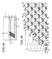
- a card-type optical recording medium C embodying the present invention as illustrated in Fig.1A has a data recording region R which includes a plurality of tracks T arranged juxtaposedly, extending longitudinally in parallel with each other and a track detecting region S provided at a part (at the left in Fig.1A) of the data recording region R.
- a plurality of track guides 1 are juxtaposed so that the tracks T may be disposed between each adjacent two guides 1, respectively as illustrated in Fig.1B.
- the lower end track guide which is denoted by 1s has an extension projecting more than the other track guides 1 for providing a lead-in 2 which is used to set an initial position of an optical head.
- each of the track guides 1 extend in lines along the length of the data recording region R as illustrated in Fig.1A.
- each of the track guides is a continuous line, but it may alternatively be a discontinuous, e.g. broken, line.
- the track guide 1 has a width and it is so formed that it can be distinctly distinguished optically (in reflectivity) from the remaining portions of the track detecting region S.
- the track guides 1 are formed to have a high reflectivity.
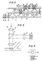
- the track detecting region S further has track number guides 3a, 3b which intersect the track guides 1 aslant. These track number guides 3a, 3b are formed in a similar manner to that of the track guides 1 as shown in Fig.2. In the present embodiment, the track number guides 3a, 3b are formed simultaneously with the track guides 1.
- These track number guides 3a, 3b are formed in continuous, solid lines in the embodiment as illustrated, but they may be discontinuous like broken lines.
- the angles ⁇ are 45°. Therefore, the track number guides 3a and 3b intersect at a right angle with each other.
- Track number detecting marks 4a, 4b are formed in the vicinity of the intersections of the track guide 1 and the track number guides 3a, 3b. These marks 4a, 4b are formed along the respective track guides 1 and disposed so as to project upwardly than the respective track guides 1 as diagrammatically shown in Fig.1B. These marks are formed in a manner similar to that of the track guides 1 as shown in Fig.2. In the present embodiment, the marks 4a, 4b are formed similarly and simultaneously with the formation of the track guides 1 and the track number guides 3a, 3b.
- Each of the track number detecting marks 4a is formed on the track guide 1 in the shape of a rectangle (square in the embodiment as illustrated) so that the track number guide 3a may pass along a diagonal thereof.
- each of the track number detecting marks 4b is formed between the track guide 1 and the track number guide 3b in the shape of a triangle.
- track numbers 5 for indicating the number of the relevant track are preliminarily written between the track number detecting marks 4a and 4b.
- the track detecting system comprises an optical system 10 as illustrated in Fig.3 and a track detection control system 20.
- the optical system 10 as illustrated in Fig.3 is basically composed of a light source 11 comprising, for example, a semiconductor laser, a collimater lens 12, a beam splitter 13, an objective lens 14, an exit lens 15, and a track detector 16.
- This optical system 10 is connected to a drive means (not shown) and adapted to move both in the direction of the track and in the direction of the width of the track.
- the optical recording medium, card may be moved in the track direction, instead of driving the optical system, while the optical system being driven in the track width direction.
- the optical system is adapted to move in the track direction, while the card being driven in the direction of the track.
- This optical system 10 is adapted to be driven, while being associated with another optical system (not shown) for reading data.
- the objective lens 14 is so arranged that its optical axis may be move by an objective lens driving means (denoted by 19 in Fig.5).
- the optical tracking for the card-type optical recording medium may be adjusted finely.
- the track detector 16 comprises a semiconductor photodetector such as a photodiode, whose effective light receiving face is divided into four discrete elements A to D. As can be seen from Fig.4, this track detector 16 is formed, in a monolithic structure, with a data detector comprising a semiconductive photodetector 17 such as a photodiode to form an optical head 18.
- This optical head 18 is so disposed that it may view, on the light receiving face of the detector, an image of a light spot L which is formed by the objective lens 14.
- the optical head 18 can therefore be considered to be at a position of the light spot L, it is explained in the following description that the optical head is hypothetically located on the light spot L.
- the track detection control unit 20 comprises a track number registering register 21 for registering a number of the track to be read; a director circuit 22 for sorting the information input from the data detector 17 into a track number and a track number detecting mark; a read track number register 23 for holding a read track number which is input through the director circuit 22; counters 24a and 24b for counting up every other track number detecting mark; a counter 25 for counting down the track number detecting marks; and a resetting circuit 26 for resetting a target value to be counted, while being based on a difference between the track number registered in the track number registering register 21 and the read track number stored in the read track number register 23.
- the track detection control unit 20 further comprises a coincidence detecting circuit 27 which compares the track number registered in the track number registering register 21 and the counted value of the counter 24b to output a coincidence or disagreement signal; a comparator circuit 28 which compares the track number registered in the track number registering register 21 and the read track number stored in the read track number register 23 to output an enable signal corresponding to the result of the comparison; a coincidence detecting circuit 29 which compares the reset value set in the resetting circuit 26 and the counted value of the counter 24a to output a coincidence or disagreement signal; and a coincidence detecting circuit 30 which compares the reset value set in the resetting circuit 26 and the counted value of the counter 25 to output a coincidence or disagreement signal.
- a coincidence detecting circuit 27 which compares the track number registered in the track number registering register 21 and the counted value of the counter 24b to output a coincidence or disagreement signal
- a comparator circuit 28 which compares the track number registered in the track number registering register 21 and the read track number stored in the
- the track detection control unit 20 further comprises an interface 31 for converting photo-outputs from the respective elements A to D of the track detector 16 into digital forms and outputting A, D, A + B and C + D; a track guide tracking drive circuit 32 for generating a signal for tracking the track guides based on the outputs A + B and C + D from the track detector 16 to output the same to a drive coil 19a of the objective lens drive means 19; a track number guide tracking drive circuit 33 for generating a signal for tracking the track number guides on the basis of the outputs from the elements A and D of the track detector 16 to output the same to a drive coil 19b of the objective lens drive means 19; an OR circuit for obtaining a logical sum of the outputs A + B and C + D; a track number detecting mark detecting circuit 35 which outputs a detection signal when it detects two successive track number detecting mark signals output from the data detector 17; and AND circuit 36 which obtains an AND of the detection signal from the detecting circuit 35 and the output from the OR circuit 34 to generate an enable
- the counters 24a, 24b and the track-width-direction movement instructing circuit 39 each have a function as a frequency divider. More specifically, the counters 24a, 24b are adapted to count one whenever they receive two detection signals and the track-width-direction movement instructing circuit 39 is adapted to output an instruction signal for moving the optical system by one track width whenever it receives two detection signals. As a result of this, the optical head 18 does not operate, for example, at a position 2 but operates at a position 2 as shown in Fig.2.
- the counter 24b is always ready to count but the counter 24a gets ready to count when the enable signal from the comparator circuit 28 is input thereto.
- the track-width-direction movement instructing circuit 39 stops its operation when a coincidence signal is output from any of the coincidence detecting circuits 27, 29 and 30 through an OR gate 40.
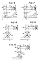
- the track guide tracking drive circuit 32 is actuated upon selection by the track guide tracking selecting circuit 37 and it compares the outputs A + B and C + D to detect a vertical deviation of the light spot L from the track guide 1 and output a correcting signal. More specifically, when the light spot L is vertically (as viewed in Figs.6 and 7) deviated from the track guide 1, the track guide tracking drive circuit 32 electrically detects unevenness in the photo-output distribution caused between the respective elements of the track detector 16, by comparing the output A + B with the output C + D as shown in Figs.6 and 7. The circuit 32 then outputs a correcting signal corresponding to the deviation to the drive coil 19a of the objective lens drive unit 19. The drive coil 19a moves the optical axis of the objective lens 14 in a direction of X shown in Figs.6 and 7 to correct the deviation of the light spot L from the track guide 1.
- the track number guide tracking drive circuit 33 is actuated upon selection by the track number guide tracking selecting circuit 38 and it compares the output A with the output D to detect vertical deviations of the light spot L from the track number guides 3a, 3b and output a correcting signal. More specifically, when the light spot L is laterally (as viewed in Figs.8 and 9) deviated for example from the track number guide 3a, the track number guide tracking drive circuit 33 detects electrically unevenness caused in the photo-output distribution among the respective elements of the track detector 16, by comparing the output A with the output D as shown in Figs.8 and 9. The circuit 33 then outputs a correcting signal corresponding to the deviation to the drive coil 19b of the objective lens drive unit 19.
- the drive coil 19b moves the optical axis of the objective lens 14 in a direction of Y as shown in Figs.8 and 9 to correct the deviation of the light spot L from the track number guide 3a for putting the light spot L into a position of Fig.10.
- the optical head 18 is positioned at the left end of the card and then moved in the direction of the width of the track to detect the lead-in 2. After detection of the lead-in 2, the card is moved from the right to the left in Fig.1B. The optical head 18 thus moves relatively in the direction of the track.
- the light beam from the light source 11 is caused to become parallel by the collimater lens 12 and forms a light spot L through the beam splitter 13 and the objective lens 14.
- the reflected light from the light spot L is incident upon the beam splitter 13 through the objective lens 14 and branched there to be projected onto the track detector 16 through the exit lens 15.
- the track detector 16 converts the luminance distribution of the image of the light spot L into electrical signals proportional to the incident light amounts by the discrete elements A to D of the track detector 16.
- the outputs from the respective elements of the track detector 16 are output as A, D, A + B and C + D through the interface circuit 31.
- the detection signal is transmitted to the counters 24a, 24b and the track-width-direction movement instructing circuit 39 through the director circuit 22.
- the data detector 17 will then detect another track number detecting mark 4a. This detection signal is also transmitted to the counters 24a, 24b and the track-width-direction movement instructing circuit 39 through the director circuit 22.
- the counter 24b counts one upon receipt of two detection signals.
- the count value is given to the coincidence detecting circuit 27.
- the coincidence circuit 27 compares the count value of the counter 24b with the registered value of the track number registering register 21. When the values coincide with each other, the circuit 27 transmits a coincidence signal to the comparator circuit 28 and the track-width-direction circuit 39. When the values do not coincide, it transmits a disagreement signal to the track number guide tracking selecting circuit 38.
- the track-width-direction movement instructing circuit 39 outputs a track-width-direction movement instruction signal upon receipt of two detection signals, subjecting to the conditions that no coincidence signals are output from the coincidence circuit 27.
- the conditions under which the coincidence signal is output show that the optical head 18 has already reached the desired track, while the disagreement signal shows that the optical head 18 has not yet reached the desired track.
- the optical head 18 When the track-width-direction movement instruction signal is output, the optical head 18 is fed by one track width in the direction thereof by the not shown step motor. In the meantime, since the card-type optical recording medium moves in the direction of the track, the optical head 18 moves along the track number guide 3a.
- the objective lens 14 may be adjusted to assure accurate tracking. More specifically, since the track number tracking drive circuit 33 is selected by the track number tracking selecting circuit 38, the correcting signal is output based on the deviation signal from the track detector 16 to operate the drive coil 19b of the objective lens drive means 19 for moving the optical axis of the objective lens 14 and correcting the deviation as described above.
- the data detector 17 Since the data detector 17 is provided at an upper position (in the figures) than the track detector 16, it detects the track number detecting mark 4b provided on the next track guide before the optical head 18 has completed its movement by one track. The detection signal is transmitted to the counters 24a, 24b and the track-width-direction movement instructing circuit 39 through the director 22 as described above.
- the number of the track guides by which the optical head 18 has passed so far is cumulatively set in the counter 24b.
- the coincidence detecting circuit 27 If the count value of the counter 24 coincides with the track number set in the track number registering register 21 when the optical head 18 is on a certain track, the coincidence detecting circuit 27 outputs a coincidence signal as described above.
- the track-width-direction movement instructing circuit 39 stops the operation.
- the optical head 18 stops its movement in the direction of the width of the track, while continuing the movement in the direction of the track alone.
- data indicative of the track number 5 are sequentially input to the data detector 17, according to the movement of the optical head 18 along the length of the track.
- the track number 5 read by the data detector 17 is stored in the track number register 23 through the director circuit 22.
- the coincidence signal as referred to above further actuates the comparator circuit 28 to compare the track number stored in the track number register 23 and the track number stored in the track number registering register 21.
- the comparator circuit 28 confirms that the optical head 18 is located on the desired track and supplies the coincidence signal to the track guide tracking selecting circuit 37.
- the track guide tracking drive circuit 32 is selected and the objective lens 14 is adjusted so that the optical spot L of the optical system may not be deviated from the track guide 1.
- the optical head 18 then travels in the direction of the track along the track guide 1 to a position of the desired track, in which data has been written, and starts to read the data.
- an enable signal is transmitted to the resetting circuit 26, the track-width-direction movement instructing circuit 39 and the counter 24a or the counter 25 according to the sign of the difference between the numbers. More specifically, if A > B, the enable signal is supplied to the counter 24a and if A ⁇ B, it is supplied to the counter 25.
- a ⁇ B indicates that the optical head 18 has not reached the desired track yet and A > B indicates that the optical head 18 has already passed over the desired track. Therefore, in the former case, the optical head 18 must be further moved in the same direction as before, but in the latter case, the optical head 18 must be moved towards the reference track guide 1s.
- the resetting circuit 26 is actuated by the enable signal to obtain a difference between the registered track number (A) and the read track number (B) and re-set the difference as a desired, target track number.
- the track-width-direction movement instructing circuit 39 releases the stopped conditions. If A > B, it outputs a track-width-direction movement instruction signal upon every two detection signals as described above. If A ⁇ B, a track-width-direction signal is output upon every one detection signal. In the latter case, however, the signal is attached with a minus sign and the movement direction of the optical head 18 is reversed.
- the track number detecting marks 4b, 4a are detected if the movement is in the upward direction (as viewed in Figs.1 and 2) as described above. In the case the movement is in the downward direction (as viewed in Figs.1 and 2), the track number detecting mark 4b positioned under the track number guide 3b can not be detected by the data detector 17 and therefore only the track number detecting mark 4a is detected.
- the detection signal from the data detector 17 is supplied to the counters 24a, 25 through the director circuit 22. As to the counters 24a, 25, either one of the counters 24a, 25 which has been input with the enable signal is operated.
- the counting results are supplied to the respectively corresponding coincidence detecting circuits 29, 30 and compared with the value set in the resetting circuit 26.
- the coincident signal is transmitted to the track-width-direction movement instructing circuit 39 through the OR gate 40 to stop the operation of the same.
- the coincidence signal is further transmitted to the track guide tracking selecting circuit 37 to select the track guide tracking drive circuit as described above.
- the coincidence signal is further transmitted to the comparator circuit 28 through the OR gate 41 to let the comparator circuit 28 compare the track number stored in the track number register 23 with the track number stored in the track number registering register 21 once more.
- the track guide tracking drive circuit 32 is selected and the objective lens 14 is adjusted so that the optical spot L of the optical system may not be deviated from the track guide 1. Then, the optical head 18 relatively moves in the direction of the track along the track guide 1 to a position of the track, in which data has been written, and reads the data.
- the optical head 18 is further moved in the same track width direction as before and such operations as described above are repeated until a coincidence signal is output as described above.
- the track number can be detected easily and quickly by detecting the track number detecting marks 4a, 4a by the optical head and the detection value can be checked through the comparison with the written track number.
- a correcting value can be reset, allowing the track detection to proceed without suspending or beginning all over again.
- the time for accessing the desired track can be curtailed very much.
- the track number detecting marks may be formed differently from the shapes of the embodiment.
- the inclinations of the track number guides may be other angles than 45°.
- the inclinations of the track number guides may be steep, for example, 60°. When the inclinations are selected to be steep, the width of the track detection region S may be narrowed.
- the inclinations of the track number guides can be 90°. In this case, however, the movement of the optical head might possibly be discontinuous.
- the track number detecting marks are provided in the optical recording medium according to the embodiment, they may be omitted. In this case, the detection of the number of the tracks is carried out by detecting and counting the number of the track guides and/or the track number guides which the data detector has passed over during the movement of the optical head along the track number guide.
Landscapes
- Moving Of The Head For Recording And Reproducing By Optical Means (AREA)
- Optical Recording Or Reproduction (AREA)
- Credit Cards Or The Like (AREA)
Claims (9)
- Optischer Aufzeichnungsträger (C) mit
einem Datenspeicherbereich (R), in dem eine Mehrzahl von Spuren (T) nebeneinanderliegen; und
eine Spure in einem Teil des Datenspeicherbereiches vorgesehenen Spurerfassungsbereich (S), dadurch gekennzeichnet, daß
der Spurerfassungsbereich Spurführungen (I) enthält, die neben je einer Spur liegen, sowie Spurzahlenführungsmitteln (3a, 3b), die dem Ort der Bewegung eines optischen Kopfes bei seinem Zugang zu einer gewünschten Spur entsprechen und die die Spurführungen kreuzen, so daß der optische Kopf den Spurzahlführungsmitteln derart nachführbar ist, daß er sich zu der gewünschten Spur bewegen und die Anzahl der gekreuzten Spurführungen erfassen kann. - Optischer Aufzeichnungsträger nach Anspruch 1, dadurch gekennzeichnet, daß die Spurzahlführungsmittel die Spurführungen schräg kreuzen.
- Optischer Aufzeichnungsträger nach Anspruch 2, dadurch gekennzeichnet, daß die Spurzahlführungsmittel Spurzahlführungen (3a) umfassen, die sich von einer Unterseite des Datenspeicherbereiches schräg zu einer Oberseite desselben erstrecken, und zwar von einer vorlaufenden Seite der Spur zu einer nachlaufenden Seite derselben hin, und Spurzahlführungen (36), die von der nachlaufenden Seite der Spur zu deren vorlaufender Seite hin abwärtsgeneigt sind.
- Optischer Aufzeichnungsträger nach Anspruch 2, dadurch gekennzeichnet, daß den Kreuzungen der Spurführungen und der Spurzahlführungsmittel Spurzahlerfassungsmarkenmittel (4a, 4b) benachbart sind.
- Optischer Aufzeichnungsträger nach Anspruch 4, dadurch gekennzeichnet, daß die Spurzahlerfassungsmarkenmittel (4a, 4b) eine den Kreuzungen der Spurführungen und der sich von der vorlaufenden Seite der Spur zu deren nachlaufender Seite hin erstreckenden Spurzahlführungen benachbarte Spurzahlerfassungsmarke (4b) und eine den Kreuzungen der sich von der nachlaufenden Seite der Spur schräg abwärts zu deren vorlaufender Seite Spurzahlführungen benachbarte Spurzahlerfassungsmarke (4a) umfassen, wobei die erstgenannten Spurzahlführungen und die letztgenannten Spurzahlführungen verschiedene Formen haben.
- Optischer Aufzeichnungsträger nach Anspruch 2, dadurch gekennzeichnet, daß längs der Spurführungen zwischen den Kreuzungen der Spurführungen und der Spurzahlführungen Spurzahlen eingeschrieben sind.
- Optischer Aufzeichnungsträger nach Anspruch 3, dadurch gekennzeichnet, daß längs der Spurführungen zwischen den Kreuzungen der Spurführungen und der Spurzahlführungen Spurzahlen eingeschrieben sind.
- Optischer Aufzeichnungsträger nach Anspruch 4, dadurch gekennzeichnet, daß längs der Spurführungen zwischen den Kreuzungen der Spurführungen und der Spurzahlführungen Spurzahlen eingeschrieben sind.
- Optischer Aufzeichnungsträger nach Anspruch 5, dadurch gekennzeichnet, daß längs der Spurführungen zwischen den Kreuzungen der Spurführungen und der Spurzahlführungen Spurzahlen eingeschrieben sind.
Applications Claiming Priority (2)
| Application Number | Priority Date | Filing Date | Title |
|---|---|---|---|
| JP196796/86 | 1986-08-22 | ||
| JP61196796A JPS6361425A (ja) | 1986-08-22 | 1986-08-22 | 光記録媒体のトラツク検出方式 |
Publications (3)
| Publication Number | Publication Date |
|---|---|
| EP0257595A2 EP0257595A2 (de) | 1988-03-02 |
| EP0257595A3 EP0257595A3 (en) | 1988-07-20 |
| EP0257595B1 true EP0257595B1 (de) | 1991-09-25 |
Family
ID=16363792
Family Applications (1)
| Application Number | Title | Priority Date | Filing Date |
|---|---|---|---|
| EP87112182A Expired EP0257595B1 (de) | 1986-08-22 | 1987-08-21 | Optisches Aufzeichnungsmedium |
Country Status (5)
| Country | Link |
|---|---|
| US (1) | US4885736A (de) |
| EP (1) | EP0257595B1 (de) |
| JP (1) | JPS6361425A (de) |
| CA (1) | CA1299746C (de) |
| DE (1) | DE3773303D1 (de) |
Families Citing this family (5)
| Publication number | Priority date | Publication date | Assignee | Title |
|---|---|---|---|---|
| JP2598952B2 (ja) * | 1988-03-18 | 1997-04-09 | 三洋電機株式会社 | トラックサーチ回路及びトラックサーチ方法 |
| US5053618A (en) * | 1990-03-30 | 1991-10-01 | Bei Electronics, Inc. | Index track support structure |
| JPH05282682A (ja) * | 1992-03-31 | 1993-10-29 | Canon Inc | 光学的情報記録再生装置 |
| JPH064906A (ja) * | 1992-06-24 | 1994-01-14 | Nippon Conlux Co Ltd | 光カード |
| JP3860339B2 (ja) | 1998-05-20 | 2006-12-20 | パイオニア株式会社 | 記録媒体製造装置及び記録媒体 |
Family Cites Families (23)
| Publication number | Priority date | Publication date | Assignee | Title |
|---|---|---|---|---|
| US4121249A (en) * | 1972-08-02 | 1978-10-17 | Lemelson Jerome H | Card recording and reproduction apparatus and method |
| US3790755A (en) * | 1961-12-08 | 1974-02-05 | D Silverman | High density information system using multiple strips |
| US3351948A (en) * | 1966-01-03 | 1967-11-07 | Honeywell Inc | Laser recorder using medium having encapsulated chemicals |
| US3919697A (en) * | 1974-06-26 | 1975-11-11 | Battelle Development Corp | Data record tracking using track identifying information in the gaps between recorded data groups |
| US4145758A (en) * | 1977-10-25 | 1979-03-20 | Drexler Technology Corporation | Error checking method and apparatus for digital data in optical recording systems |
| US4107746A (en) * | 1977-10-25 | 1978-08-15 | Control Data Corporation | Continuous spiral mode tracking in a conventional disk drive using concentric servo tracks |
| WO1980000200A1 (en) * | 1978-07-07 | 1980-02-07 | News Log Int Inc | Microfiche information and control system |
| US4269917A (en) * | 1979-07-06 | 1981-05-26 | Drexler Technology Corporation | Data storage medium having reflective particulate silver layer |
| US4278758A (en) * | 1979-07-06 | 1981-07-14 | Drexler Technology Corporation | Process for making a reflective data storage medium |
| US4278756A (en) * | 1979-07-06 | 1981-07-14 | Drexler Technology Corporation | Reflective data storage medium made by silver diffusion transfer |
| US4500777A (en) * | 1981-02-27 | 1985-02-19 | Drexler Technology Corporation | High data capacity, scratch and dust resistant, infrared, read-write data card for automatic teller machines |
| US4542288A (en) * | 1981-02-27 | 1985-09-17 | Drexler Technology Corporation | Method for making a laser recordable wallet-size plastic card |
| US4544835A (en) * | 1983-12-29 | 1985-10-01 | Drexler Technology Corporation | Data system containing a high capacity optical contrast laser recordable wallet-size plastic card |
| US4360728A (en) * | 1981-02-27 | 1982-11-23 | Drexler Technology Corporation | Banking card for automatic teller machines and the like |
| US4417330A (en) * | 1981-10-15 | 1983-11-22 | Burroughs Corporation | Optical memory system providing improved focusing control |
| DE3277512D1 (en) * | 1981-12-01 | 1987-11-26 | Matsushita Electric Industrial Co Ltd | Optical recording and reproducing disc |
| GB8309447D0 (en) * | 1983-04-07 | 1983-05-11 | Combined Tech Corp Plc | Optical data storage |
| JPS59193556A (ja) * | 1983-04-15 | 1984-11-02 | Tdk Corp | 光カ−ド |
| US4598393A (en) * | 1984-04-06 | 1986-07-01 | Drexler Technology Corporation | Three-beam optical servo tracking system with two-track parallel readout |
| JPS61243970A (ja) * | 1985-04-22 | 1986-10-30 | Canon Inc | 光学的情報記録媒体 |
| CA1258909A (en) * | 1985-03-29 | 1989-08-29 | Hideki Hosoya | Optical information recording medium and method for recording information on said medium and reproducing information therefrom |
| JPS61243973A (ja) * | 1985-04-22 | 1986-10-30 | Canon Inc | 光学的情報記録媒体 |
| JPH06243844A (ja) * | 1993-02-16 | 1994-09-02 | Harrison Denki Kk | 管球用マウント製造装置 |
-
1986
- 1986-08-22 JP JP61196796A patent/JPS6361425A/ja active Pending
-
1987
- 1987-08-21 US US07/088,727 patent/US4885736A/en not_active Expired - Fee Related
- 1987-08-21 EP EP87112182A patent/EP0257595B1/de not_active Expired
- 1987-08-21 DE DE8787112182T patent/DE3773303D1/de not_active Expired - Fee Related
- 1987-08-24 CA CA000545146A patent/CA1299746C/en not_active Expired - Fee Related
Also Published As
| Publication number | Publication date |
|---|---|
| CA1299746C (en) | 1992-04-28 |
| JPS6361425A (ja) | 1988-03-17 |
| EP0257595A2 (de) | 1988-03-02 |
| US4885736A (en) | 1989-12-05 |
| DE3773303D1 (de) | 1991-10-31 |
| EP0257595A3 (en) | 1988-07-20 |
Similar Documents
| Publication | Publication Date | Title |
|---|---|---|
| US4918415A (en) | Data reading and/or writing apparatus for use with an optical card | |
| JP2000314611A (ja) | 物体位置決定システム | |
| EP0743636B1 (de) | Platteneichverfahren in einem CD-ROM Antriebssystem | |
| WO1988009021A1 (en) | Read-only optical card and system | |
| EP0279696B1 (de) | Zugriffsverfahren zu einer Spur eines Aufzeichnungsmediums im stillstehenden Zustand und Gerät dafür | |
| NL8004333A (nl) | Informatiebevattende inrichting. | |
| EP0303377A1 (de) | Verfahren zur Aufzeichnung von Positionsinformation der letzten Spur von Daten in einem Leitspurbereich | |
| EP0257595B1 (de) | Optisches Aufzeichnungsmedium | |
| EP0074115A1 (de) | Vorrichtung zum Feststellen von Defekten mittels eines aussermittigen Lichtstrahles | |
| US6194697B1 (en) | Calibration system for an imaging apparatus and method | |
| ATE141435T1 (de) | Optische abtastvorrichtung | |
| US4881215A (en) | Optical recording medium and method for correcting angular deviation thereof | |
| US4866686A (en) | Optical record carrier and apparatus for reading the record carrier | |
| CA1294705C (en) | Optical information recording medium and recording-reproducing apparatus | |
| US5128946A (en) | Information recording-reproducing method and apparatus | |
| KR910000333B1 (ko) | 광 기록매체 | |
| US5144610A (en) | Method of recording data on optical card by performing blank checking without scanning an entire track | |
| US5179267A (en) | Data reading and/or writing apparatus of type using optical card | |
| JPH05282682A (ja) | 光学的情報記録再生装置 | |
| EP0503095B1 (de) | Suchsteuersystem für magneto-optisches scheibenantriebsgerät | |
| JP2800155B2 (ja) | 情報記録再生方法 | |
| CA1303741C (en) | Method of accessing track in still state of recording medium and apparatus therefor | |
| JPH069088B2 (ja) | 光学的情報記録再生方法及び光学的情報記録再生装置 | |
| JP2746314B2 (ja) | 光カード情報記録再生方法 | |
| JPS6218676A (ja) | 情報記録方法 |
Legal Events
| Date | Code | Title | Description |
|---|---|---|---|
| PUAI | Public reference made under article 153(3) epc to a published international application that has entered the european phase |
Free format text: ORIGINAL CODE: 0009012 |
|
| AK | Designated contracting states |
Kind code of ref document: A2 Designated state(s): DE FR GB |
|
| PUAL | Search report despatched |
Free format text: ORIGINAL CODE: 0009013 |
|
| AK | Designated contracting states |
Kind code of ref document: A3 Designated state(s): DE FR GB |
|
| 17P | Request for examination filed |
Effective date: 19881228 |
|
| 17Q | First examination report despatched |
Effective date: 19901130 |
|
| GRAA | (expected) grant |
Free format text: ORIGINAL CODE: 0009210 |
|
| AK | Designated contracting states |
Kind code of ref document: B1 Designated state(s): DE FR GB |
|
| REF | Corresponds to: |
Ref document number: 3773303 Country of ref document: DE Date of ref document: 19911031 |
|
| ET | Fr: translation filed | ||
| PGFP | Annual fee paid to national office [announced via postgrant information from national office to epo] |
Ref country code: FR Payment date: 19920730 Year of fee payment: 6 |
|
| PLBE | No opposition filed within time limit |
Free format text: ORIGINAL CODE: 0009261 |
|
| STAA | Information on the status of an ep patent application or granted ep patent |
Free format text: STATUS: NO OPPOSITION FILED WITHIN TIME LIMIT |
|
| PGFP | Annual fee paid to national office [announced via postgrant information from national office to epo] |
Ref country code: GB Payment date: 19920819 Year of fee payment: 6 |
|
| PGFP | Annual fee paid to national office [announced via postgrant information from national office to epo] |
Ref country code: DE Payment date: 19920820 Year of fee payment: 6 |
|
| 26N | No opposition filed | ||
| PG25 | Lapsed in a contracting state [announced via postgrant information from national office to epo] |
Ref country code: GB Effective date: 19930821 |
|
| GBPC | Gb: european patent ceased through non-payment of renewal fee |
Effective date: 19930821 |
|
| PG25 | Lapsed in a contracting state [announced via postgrant information from national office to epo] |
Ref country code: FR Effective date: 19940429 |
|
| PG25 | Lapsed in a contracting state [announced via postgrant information from national office to epo] |
Ref country code: DE Effective date: 19940503 |
|
| REG | Reference to a national code |
Ref country code: FR Ref legal event code: ST |