EP0257687A2 - Système de transmission numérique - Google Patents
Système de transmission numérique Download PDFInfo
- Publication number
- EP0257687A2 EP0257687A2 EP87201504A EP87201504A EP0257687A2 EP 0257687 A2 EP0257687 A2 EP 0257687A2 EP 87201504 A EP87201504 A EP 87201504A EP 87201504 A EP87201504 A EP 87201504A EP 0257687 A2 EP0257687 A2 EP 0257687A2
- Authority
- EP
- European Patent Office
- Prior art keywords
- signal
- input
- output
- frequency
- div
- Prior art date
- Legal status (The legal status is an assumption and is not a legal conclusion. Google has not performed a legal analysis and makes no representation as to the accuracy of the status listed.)
- Withdrawn
Links
Images

Classifications
-
- H—ELECTRICITY
- H04—ELECTRIC COMMUNICATION TECHNIQUE
- H04M—TELEPHONIC COMMUNICATION
- H04M1/00—Substation equipment, e.g. for use by subscribers
- H04M1/26—Devices for calling a subscriber
- H04M1/30—Devices which can set up and transmit only one digit at a time
- H04M1/50—Devices which can set up and transmit only one digit at a time by generating or selecting currents of predetermined frequencies or combinations of frequencies
- H04M1/505—Devices which can set up and transmit only one digit at a time by generating or selecting currents of predetermined frequencies or combinations of frequencies signals generated in digital form
-
- G—PHYSICS
- G06—COMPUTING OR CALCULATING; COUNTING
- G06F—ELECTRIC DIGITAL DATA PROCESSING
- G06F1/00—Details not covered by groups G06F3/00 - G06F13/00 and G06F21/00
- G06F1/02—Digital function generators
- G06F1/025—Digital function generators for functions having two-valued amplitude, e.g. Walsh functions
Definitions
- the present invention relates to a digital transmission system and more particularly to a digital transmission system including a signal generator, itself including a chopper circuit wherein an input signal having a first fundamental frequency is chopped by a chopper signal having a second fundamental frequency larger than said first fundamental frequency and which provides an output signal which is constituted by said chopper signal modulated by said input signal.
- the frequency spectrum of the output signal is dependent on the frequency spectrum of both the input and the chopper signals since it contains mixing products of the constituent frequencies of these signals.
- An object of the present invention is to provide a signal generator of the above type but wherein the frequency spectrum of the output signal is substantially affected only by the frequency spectrum of the input signal.
- a generator is particularly, but not exclusively, applicable to the generation of audible tones in a telephone subset by removing the unwanted higher frequencies from the modulated digital output signals.
- this object is achieved due to the fact that said input signal is a square wave, whilst said chopper signal is a rectangular wave whose said second fundamental frequency is an even multiple of said first fundamental frequency.
- the frequency content of the spectrum of the output signal is identical to that of the input signal, the above mentioned mixing products produced by the chopping operation coinciding with harmonics of the input signal.
- said signal generator includes means for modifying the duty cycle of said rectangular wave.
- one of the advantages of such a digital signal generator endowing a chopper circuit with output signals of variable frequency and amplitude is that one may now produce such signals without resorting to memories storing digital values corresponding to instantaneous amplitudes of the desired signals.
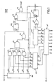
- the signal or tone generator GEN shown in Fig. 1 is used in a telecommunication system and more particularly in a telphone subset to generate audible tone and ringing signals having a frequency and an amplitude which are selectable by an incoming 8 bits digital word.
- Each bit of this digital word is applied to a distinct input terminal 10/7 of a latch circuit LAT.
- the 5 least significant bits LSB of the digital word appearing at output terminals F0/4 of LAT are used to select the frequency of the tone, whilst the 3 remaining most significant bits MSB appearing at output terminals X, Y and Z of LAT are used to select the amplitude of this tone.
- the operation of the latch circuit LAT is controlled via a control terminal CTL.
- the tone generator GEN is driven by a 2,048 kHz clock signal CLK supplied at a like-named input terminal CLK.
- the part of GEN controlling the frequency of the tone includes a counter CNT coupled to LAT via the terminals F0/4.
- CNT is controlled by a 32 kHz signal SA0 (Figs. 3 and 4) supplied at a terminal A0 (Fig. 1) of a divider DIV which derives this signal SA0 from the 2,048 kHz clock signal CLK as will be explained later.
- CNT has an output terminal T1 which is connected to a first input of an exclusive-NOR gate X1 whose output is connected to the data input D of a D-flipflop FF1.
- the Q output terminal Q1 of FF1 is fed back to a second input of X1 and is also connected to a first input of another exclusive-NOR gate X2 whilst the above terminal A0 is connected to the clock input CK of FF1.
- this part of GEN provides at its terminal Q1 a square wave having a frequency adjustable between 500 Hz and 16 kHz equal to the frequency of the required tone.
- the part of GEN controlling the amplitude of the tone includes the above mentioned divider DIV driven by the clock signal CLK.
- DIV has five output terminals A0/4 each providing a signal whose frequency is a submultiple of the frequency (2,048 kHz) of the clock signal CLK. More particularly, signals with frequencies of 32 kHz, 64 kHz, 128 kHz, 256 kHz and 512 kHz are provided at the terminals A0, A1, A2, A3 and A4 respectively.
- the terminals A1/4 are each connected to a first input of NAND gates E1/4 a second input of which is connected to a respective output terminal C1/4 of a decoder DEC also included in GEN.
- DEC has a fifth output terminal C0 and three input terminals X, Y and Z which are respectively connected to the above mentioned like-named output terminals of LAT.
- the outputs of the NAND gates E1/4 are all connected to respective inputs of a NAND gate E5 whose output is connected to a first input of a NAND gate E0.
- the terminal A0 of DIV is connected to a second input of E0 and the output of the latter is connected to the data input D of a second D-flipflop FF2.
- Terminal CLK is connected to the clock input CK of FF2 whose Q output terminal Q2 is connected to a second input of the exclusive-NOR gate X2.
- this part of GEN provides at its terminal Q2 a rectangular wave at 32 kHz whose selectable duty cycle determines the amplitude of the required tone.
- the square wave at Q1 is chopped by the rectangular wave at Q2 in the chopper circuit constituted by X2.
- the output of X2 and the output terminal C0 of DEC are respectively connected to a first and a second inputs of a NOR gate R1.
- the output of R1 is connected to an output terminal OUT of GEN where a rectangular wave output signal corresponding to the required tone is available.
- a loudspeaker (not shown) connected to this terminal OUT, e.g. via a low pass filter circuit, may transform this output signal into a sound.
- the decoder DEC is represented in more detail in Fig. 2. It comprises two NOR gates R2 and R3, two NAND gates E6 and E7 and one inverter I1.
- R2 and E6 each have two inputs respectively connected to the terminals Y and Z, I1 has its input connected to Z whilst E7 and R3 each have three inputs respectively connected to X, Y and Z.
- the outputs of R3, E7, E6, I1 and R2 are connected to the terminals C0, C1, C2, C3 and C4 respectively.
- the truth table of the decoder DEC is as follows :
- DEC only has 6 and not 8 different output combinations since the binary value at terminal X is immaterial when the binary values at the terminals Y and Z are not equal to one another. This is sufficient for the present application (telephony) and simplifies the structure of this decoder DEC which uses only simple logical gates.
- tone generator GEN The operation of the tone generator GEN is described hereinafter.
- the signal SA0 of 32 kHz is divided by a number N which is equal to the two's complement of the binary value of the 5 LSB I0/4 of the incoming digital word plus 1.
- This binary value stored in the latch circuit LAT, is transmitted to CNT via the terminals F0/4 and is used as start value for CNT which increments it to 0 at the frequency of 32 kHz.
- a pulse is provided at the output terminal T1 and the counter CNT is reset to its start value.
- This output signal is transformed into a square wave at Q1 by the divider-by-two circuit constituted by X1 and FF1.
- each pulse generated on T1 produces a raising or a falling edge of this square wave so that the frequency of the signal at this terminal Q1 is the half the frequency of the pulses generated on T1.
- a table indicating the relation between the 5 bits binary value at F4/0 and the frequency of the signal at the terminal Q1 is given below :
- the 32 kHz signal SA0 is divided by the binary value 100000 in CNT and the resulting signal at Q1 has a frequency of 500 Hz which is the lowest possible frequency at Q1.
- the highest frequency on Q1 is obtained when the start value has the binary value 00000 and is equal to 16 kHz.
- the 500 Hz to 16 kHz square wave signal provided at terminal Q1 has an amplitude of, e.g., 5 Volts peak to peak and this is the maximum possible amplitude of the tone generated on terminal OUT.
- this square wave signal generated on Q1 is chopped by the above mentioned rectangular wave at 32 kHz and which has a selectable duty cycle.
- the resulting rectangular signal generated on terminal OUT still has an amplitude of 5 Volts peak to peak but the amplitude of the corresponding audible sound is reduced according to the value of the duty cycle of the rectangular wave.
- Such a rectangular wave with a variable duty cycle or pulse width is provided by the part of GEN controlling the amplitude of the output signal, as will be explained hereinafter.
- the amplitude of the output signal of GEN is determined by the 3 MSB 15/7 of the digital word. These 3 bits, which are stored in the latch circuit LAT, are applied to the decoder DEC via the terminals X, Y and Z so that a corresponding digital output number appears at the terminals C0/4 in accordance with the above given truth table of DEC.
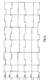
- the divider DIV uses the 2,048 kHz clock signal CLK to supply square wave frequency signals SA4/0 as shown in Fig. 3.
- the signals SA4 of 512 kHz, SA3 of 256 kHz, SA2 of 128 kHz, SA1 of 64 kHz and SA0 of 32 kHz are supplied at the output terminals A4, A3, A2, A1 and A0 respectively.
- the 32 kHz signal SA0 supplied at terminal A0 is used by CNT and FF1.
- Each of the other frequency signals SA4/1 is sent to one of the corresponding NAND gates E4/1 where it is combined with a bit of the digital output number at the terminals C4/1.
- the change of the binary value of the signals at the outputs of E5 to E1 is not instantaneous so that the NAND operation on these signals may generate unwanted pulses which appear in the signal SE0, especially when the binary value of the latter signal SE0 is not changed.
- the D-flipflop FF2 samples the signal SE0 at the clock frequency CLK of 2,048 kHz when the binary value of the signal SE0 is stable, i.e. not during the above transient states. The binary value of each sample is then provided at the output terminal Q2 of FF2 which remains in this state until a new sample is taken.
- the purpose of FF2 is to reshape the signal SE0 so that the signal at the terminal Q2 is in fact identical to the ideal value of signal SE0 at the output of E0.
- the square wave at terminal Q1 and the rectangular wave SE0 at terminal Q2 are both applied to the chopper circuit X2 in order to produce on the terminal OUT a rectangular wave corresponding to the desired tone.
- the signal SQ1 at the terminal Q1 has a frequency of 8 kHz so that the signal at the output of X2 and therefore also at the output terminal OUT is a rectangular wave SX2.
- the signal SQ1 ⁇ at Q1 has a frequency of 4 kHz so that the signal at OUT is then a rectangular wave SX2 ⁇ .
- the amplitude of the sound is zero when the terminals Z, Y and X are all three at the binary value 0.
- the modified duty cycle of the rectangular signal at OUT causes the amplitude of the corresponding sound to increase logarithmically due to the particular truth table defined above.
- These five values, successively doubling the amplitude correspond respectively to 0 bits for C1 to C4, C2 to C4, C3 and C4, C4 and none, i.e. 1 bits for C1 to C4.
- the square wave SQ1 has a fundamental frequency f0 which is equal to the freqency f1 divided by 2 and by N, with N larger or equal to 1 and smaller or equal to 32.
- SQ1 B j . sin [ (2j + 1) . 2 ⁇ f0 + 0 ⁇ j ) ] where B j is the amplitude, 0 ⁇ j the phase, f0 the frequency and j a variable going from zero to infinity.
Landscapes
- Engineering & Computer Science (AREA)
- Theoretical Computer Science (AREA)
- Physics & Mathematics (AREA)
- General Engineering & Computer Science (AREA)
- General Physics & Mathematics (AREA)
- Signal Processing (AREA)
- Analogue/Digital Conversion (AREA)
- Devices For Supply Of Signal Current (AREA)
- Transmitters (AREA)
Applications Claiming Priority (2)
| Application Number | Priority Date | Filing Date | Title |
|---|---|---|---|
| BE2061029 | 1986-08-12 | ||
| BE2/61029A BE905260R (fr) | 1986-08-12 | 1986-08-12 | Systeme de transmission numerique. |
Publications (2)
| Publication Number | Publication Date |
|---|---|
| EP0257687A2 true EP0257687A2 (fr) | 1988-03-02 |
| EP0257687A3 EP0257687A3 (fr) | 1989-12-20 |
Family
ID=3865818
Family Applications (1)
| Application Number | Title | Priority Date | Filing Date |
|---|---|---|---|
| EP87201504A Withdrawn EP0257687A3 (fr) | 1986-08-12 | 1987-08-06 | Système de transmission numérique |
Country Status (3)
| Country | Link |
|---|---|
| US (1) | US4803437A (fr) |
| EP (1) | EP0257687A3 (fr) |
| AU (1) | AU593671B2 (fr) |
Cited By (3)
| Publication number | Priority date | Publication date | Assignee | Title |
|---|---|---|---|---|
| EP0312192A3 (fr) * | 1987-10-10 | 1991-04-03 | Nortel Networks Corporation | Convertisseur numérique de fréquence |
| GB2256775A (en) * | 1991-06-12 | 1992-12-16 | Mitel Corp | Digitally controlled ringer signal generator |
| US6433673B1 (en) * | 1998-09-25 | 2002-08-13 | Conexant Systems, Inc. | Digital enunciator, process and communication system employing same |
Families Citing this family (6)
| Publication number | Priority date | Publication date | Assignee | Title |
|---|---|---|---|---|
| US5150415A (en) * | 1989-05-01 | 1992-09-22 | Motorola, Inc. | Volume control circuit using pulse modulation |
| JP2001508628A (ja) * | 1997-01-15 | 2001-06-26 | 3コム コーポレイション | 加入者回線のインターフェース回路(slic)シミュレータ |
| JPH10336018A (ja) * | 1997-05-28 | 1998-12-18 | Fujitsu Ltd | 可変分周器及びpll回路 |
| US6667704B1 (en) * | 2001-08-15 | 2003-12-23 | Cirrus Logic, Inc. | Data conversion circuits and methods with input clock signal frequency detection and master mode output clock signal generation |
| US8140026B2 (en) * | 2009-05-06 | 2012-03-20 | Qualcomm Incorporated | All-digital selectable duty cycle generation |
| CN120320767B (zh) * | 2025-03-28 | 2025-11-04 | 苏州异格技术有限公司 | 一种输出占空比50%的连续整数分频器 |
Family Cites Families (4)
| Publication number | Priority date | Publication date | Assignee | Title |
|---|---|---|---|---|
| US3464018A (en) * | 1966-08-26 | 1969-08-26 | Nasa | Digitally controlled frequency synthesizer |
| US3838348A (en) * | 1973-06-25 | 1974-09-24 | Bell Telephone Labor Inc | Digital multifrequency signal generator |
| GB1486811A (en) * | 1973-09-03 | 1977-09-28 | Nz Inventions Dev Authority | Waveform synthesis using switching circuits |
| JPS5843187A (ja) * | 1981-09-03 | 1983-03-12 | Fuji Electric Co Ltd | 可変周波発振方式 |
-
1987
- 1987-07-30 AU AU76312/87A patent/AU593671B2/en not_active Ceased
- 1987-08-06 EP EP87201504A patent/EP0257687A3/fr not_active Withdrawn
- 1987-08-12 US US07/084,250 patent/US4803437A/en not_active Expired - Fee Related
Cited By (4)
| Publication number | Priority date | Publication date | Assignee | Title |
|---|---|---|---|---|
| EP0312192A3 (fr) * | 1987-10-10 | 1991-04-03 | Nortel Networks Corporation | Convertisseur numérique de fréquence |
| GB2256775A (en) * | 1991-06-12 | 1992-12-16 | Mitel Corp | Digitally controlled ringer signal generator |
| GB2256775B (en) * | 1991-06-12 | 1995-12-13 | Mitel Corp | Digitally controlled ringer signal generation |
| US6433673B1 (en) * | 1998-09-25 | 2002-08-13 | Conexant Systems, Inc. | Digital enunciator, process and communication system employing same |
Also Published As
| Publication number | Publication date |
|---|---|
| AU7631287A (en) | 1988-02-18 |
| AU593671B2 (en) | 1990-02-15 |
| US4803437A (en) | 1989-02-07 |
| EP0257687A3 (fr) | 1989-12-20 |
Similar Documents
| Publication | Publication Date | Title |
|---|---|---|
| US3868601A (en) | Digital single-sideband modulator | |
| US3215860A (en) | Clock pulse controlled sine wave synthesizer | |
| US3991389A (en) | Digital frequency shift key modulator | |
| US4727570A (en) | Waveform generators | |
| EP0257687A2 (fr) | Système de transmission numérique | |
| JPH0936664A (ja) | 周波数変換回路 | |
| US4259648A (en) | One-bit frequency-shift-keyed modulator | |
| US3654558A (en) | Frequency divider circuit for producing a substantially sawtooth wave | |
| US4352210A (en) | Linear mixer with reduced spurious responses | |
| US4639554A (en) | Dual-tone multiple-frequency-signal generating apparatus | |
| US3999049A (en) | Synthesizer of multifrequency code signals | |
| US5892692A (en) | Method for generating a lookup table for a digital oscillator | |
| KR910001675B1 (ko) | 이중음 다중주파수 및 고저음 발생회로 | |
| US5936438A (en) | Digital oscillator using lookup table with multiple cycles | |
| US5461583A (en) | Programmable frequency sine wave signal generator | |
| JP2619961B2 (ja) | Pwm方式ディジタルアナログ変換器用クロック発生装置 | |
| US4775805A (en) | Differential frequency signal generator | |
| GB2066628A (en) | Circuit arrangement for transmitting binary data elements as two tone frequences | |
| US3943454A (en) | Digital logic circuits for producing digital sum and difference frequencies | |
| US5231240A (en) | Digital tone mixer | |
| DE4041852A1 (de) | Digitales schaltsignal in stereodekodern und schaltungsanordnung zu seiner erzeugung | |
| US4313360A (en) | Harmonic generator for additive synthesis of musical tones | |
| GB2247792A (en) | Sinewave generators | |
| US3825775A (en) | Circuit arrangement for converting square waves into asymmetrical rectangular waves | |
| US4604935A (en) | Apparatus and method for processing audio signals |
Legal Events
| Date | Code | Title | Description |
|---|---|---|---|
| PUAI | Public reference made under article 153(3) epc to a published international application that has entered the european phase |
Free format text: ORIGINAL CODE: 0009012 |
|
| AK | Designated contracting states |
Kind code of ref document: A2 Designated state(s): AT BE CH DE FR GB IT LI NL SE |
|
| RAP3 | Party data changed (applicant data changed or rights of an application transferred) |
Owner name: ALCATEL N.V. |
|
| PUAL | Search report despatched |
Free format text: ORIGINAL CODE: 0009013 |
|
| AK | Designated contracting states |
Kind code of ref document: A3 Designated state(s): AT BE CH DE FR GB IT LI NL SE |
|
| 17P | Request for examination filed |
Effective date: 19900526 |
|
| 17Q | First examination report despatched |
Effective date: 19920310 |
|
| STAA | Information on the status of an ep patent application or granted ep patent |
Free format text: STATUS: THE APPLICATION IS DEEMED TO BE WITHDRAWN |
|
| 18D | Application deemed to be withdrawn |
Effective date: 19931113 |
|
| RIN1 | Information on inventor provided before grant (corrected) |
Inventor name: REUSENS, PETER PAUL FRANS |