EP0257690A2 - Kolbenkonstruktion für ein Druckminderventil - Google Patents
Kolbenkonstruktion für ein Druckminderventil Download PDFInfo
- Publication number
- EP0257690A2 EP0257690A2 EP87201518A EP87201518A EP0257690A2 EP 0257690 A2 EP0257690 A2 EP 0257690A2 EP 87201518 A EP87201518 A EP 87201518A EP 87201518 A EP87201518 A EP 87201518A EP 0257690 A2 EP0257690 A2 EP 0257690A2
- Authority
- EP
- European Patent Office
- Prior art keywords
- piston
- valve
- pressure
- point
- pressure reducing
- Prior art date
- Legal status (The legal status is an assumption and is not a legal conclusion. Google has not performed a legal analysis and makes no representation as to the accuracy of the status listed.)
- Withdrawn
Links
Images

Classifications
-
- F—MECHANICAL ENGINEERING; LIGHTING; HEATING; WEAPONS; BLASTING
- F16—ENGINEERING ELEMENTS AND UNITS; GENERAL MEASURES FOR PRODUCING AND MAINTAINING EFFECTIVE FUNCTIONING OF MACHINES OR INSTALLATIONS; THERMAL INSULATION IN GENERAL
- F16K—VALVES; TAPS; COCKS; ACTUATING-FLOATS; DEVICES FOR VENTING OR AERATING
- F16K31/00—Actuating devices; Operating means; Releasing devices
- F16K31/12—Actuating devices; Operating means; Releasing devices actuated by fluid
- F16K31/14—Actuating devices; Operating means; Releasing devices actuated by fluid for mounting on, or in combination with, hand-actuated valves
- F16K31/143—Actuating devices; Operating means; Releasing devices actuated by fluid for mounting on, or in combination with, hand-actuated valves the fluid acting on a piston
-
- F—MECHANICAL ENGINEERING; LIGHTING; HEATING; WEAPONS; BLASTING
- F16—ENGINEERING ELEMENTS AND UNITS; GENERAL MEASURES FOR PRODUCING AND MAINTAINING EFFECTIVE FUNCTIONING OF MACHINES OR INSTALLATIONS; THERMAL INSULATION IN GENERAL
- F16K—VALVES; TAPS; COCKS; ACTUATING-FLOATS; DEVICES FOR VENTING OR AERATING
- F16K31/00—Actuating devices; Operating means; Releasing devices
- F16K31/12—Actuating devices; Operating means; Releasing devices actuated by fluid
- F16K31/36—Actuating devices; Operating means; Releasing devices actuated by fluid in which fluid from the circuit is constantly supplied to the fluid motor
- F16K31/38—Actuating devices; Operating means; Releasing devices actuated by fluid in which fluid from the circuit is constantly supplied to the fluid motor in which the fluid works directly on both sides of the fluid motor, one side being connected by means of a restricted passage and the motor being actuated by operating a discharge from that side
- F16K31/383—Actuating devices; Operating means; Releasing devices actuated by fluid in which fluid from the circuit is constantly supplied to the fluid motor in which the fluid works directly on both sides of the fluid motor, one side being connected by means of a restricted passage and the motor being actuated by operating a discharge from that side the fluid acting on a piston
-
- F—MECHANICAL ENGINEERING; LIGHTING; HEATING; WEAPONS; BLASTING
- F16—ENGINEERING ELEMENTS AND UNITS; GENERAL MEASURES FOR PRODUCING AND MAINTAINING EFFECTIVE FUNCTIONING OF MACHINES OR INSTALLATIONS; THERMAL INSULATION IN GENERAL
- F16K—VALVES; TAPS; COCKS; ACTUATING-FLOATS; DEVICES FOR VENTING OR AERATING
- F16K31/00—Actuating devices; Operating means; Releasing devices
- F16K31/12—Actuating devices; Operating means; Releasing devices actuated by fluid
- F16K31/122—Actuating devices; Operating means; Releasing devices actuated by fluid the fluid acting on a piston
-
- F—MECHANICAL ENGINEERING; LIGHTING; HEATING; WEAPONS; BLASTING
- F16—ENGINEERING ELEMENTS AND UNITS; GENERAL MEASURES FOR PRODUCING AND MAINTAINING EFFECTIVE FUNCTIONING OF MACHINES OR INSTALLATIONS; THERMAL INSULATION IN GENERAL
- F16K—VALVES; TAPS; COCKS; ACTUATING-FLOATS; DEVICES FOR VENTING OR AERATING
- F16K47/00—Means in valves for absorbing fluid energy
- F16K47/08—Means in valves for absorbing fluid energy for decreasing pressure or noise level and having a throttling member separate from the closure member, e.g. screens, slots, labyrinths
-
- G—PHYSICS
- G05—CONTROLLING; REGULATING
- G05D—SYSTEMS FOR CONTROLLING OR REGULATING NON-ELECTRIC VARIABLES
- G05D16/00—Control of fluid pressure
- G05D16/14—Control of fluid pressure with auxiliary non-electric power
- G05D16/16—Control of fluid pressure with auxiliary non-electric power derived from the controlled fluid
- G05D16/166—Control of fluid pressure with auxiliary non-electric power derived from the controlled fluid using pistons within the main valve
-
- Y—GENERAL TAGGING OF NEW TECHNOLOGICAL DEVELOPMENTS; GENERAL TAGGING OF CROSS-SECTIONAL TECHNOLOGIES SPANNING OVER SEVERAL SECTIONS OF THE IPC; TECHNICAL SUBJECTS COVERED BY FORMER USPC CROSS-REFERENCE ART COLLECTIONS [XRACs] AND DIGESTS
- Y10—TECHNICAL SUBJECTS COVERED BY FORMER USPC
- Y10T—TECHNICAL SUBJECTS COVERED BY FORMER US CLASSIFICATION
- Y10T137/00—Fluid handling
- Y10T137/7722—Line condition change responsive valves
- Y10T137/7758—Pilot or servo controlled
- Y10T137/7762—Fluid pressure type
- Y10T137/7764—Choked or throttled pressure type
- Y10T137/7768—Pilot controls supply to pressure chamber
Definitions
- This invention relates to a pressure reducing valve mounted in a piping system for steam, compressed air, etc. to maintain the secondary side fluid pressure at a certain set level and the invention particularly relates to a piston structure for a type of pressure reducing valve in which the primary side fluid pressure acts on the upper surface of the piston through a pilot valve which is opened and closed in response to the secondary side pressure and the piston is operated by a pressure difference between said upper surface and the lower surface of the piston, the latter being exposed to the secondary side pressure, said piston being arranged to operatively open and close a main valve.
- This type of pressure reducing valve permits the primary side fluid introduced through the pilot valve to the upper surface of the piston to act on the upper surface of the piston while the fluid escapes through a gap between the piston and a piston receiving cylinder to regulate the fluid pressure acting on the upper surface of the piston.
- the main valve controlling piston is provided on the side with two annular grooves in which piston rings are disposed such that when the piston is inserted into a cylinder the piston rings expand radially to uniformly contact the inner surface of the cylinder.
- the piston may be tilted by fluid jetted from the main valve so that the upper corner area of the piston interferes with the inner peripheral surface of the cylinder, resulting in malfunction because smooth sliding is impeded.
- the two piston grooves should be arranged as far as possible from each other so that it is difficult for the piston to tilt within the cylinder. Such enlarging of the spacing between the two piston grooves inevitably leads to thinning of the upper wall between the upper annular groove and the upper surface of the piston.
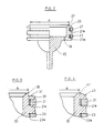
- the said problems are solved in that in a type of pressure reducing valve wherein a piston having in its side surface at least one annular groove, a piston ring received in said groove, said piston being slidably movable in a cylinder for opening and closing a main valve and wherein the operating pressure of said piston is regulated by a pilot valve which operates in response to the secondary pressure according to the invention, the outer peripheral edge of the upper surface of the piston is made lower than a point on said upper surface, located on the same radius as the bottom surface of the said piston ring receiving annular groove formed in the side surface of said piston or a point located on a lesser radius.
- Fig. l is a sectional view showing a pressure reducing valve for steam in which a first embodiment of piston is built (see Fig. 2).
- This pressure reducing valve comprises a pressure reducing valve section l, a gas-water separator section 2 and a drain valve section 3.
- a valve casing l0 is formed with an inlet l2, a valve port l4 and an outlet l6.
- the inlet l2 is connected to the primary side high pressure fluid source and the outlet l6 to the secondary side low pressure region.
- the valve port l4 is formed within a valve seat member.
- a piston 20 is formed having a side surface with annular grooves in which are disposed piston rings 2l, 23.
- the piston 20 carrying the piston rings 2l, 22 is slidably inserted into a cylinder 22 with elastic members 2la, 23a urging the piston rings from the radially outside.
- a piston rod extends through the valve port l4 and is adapted to abut against a main valve l8 to open an orifice l9 affording communication between the upper and lower side of the piston.
- the piston is provided on the upper surface with a tapered surface 25 inclined from a point 27 on the circumference of a circle having the same diameter A as the bottom of the piston ring receiving annular groove, and downwardly diverging in the outer peripheral direction.
- the thus formed angle between this tapered surface 25 and the upper surface of the piston such that the tapered surface does not abut against the inner wall of main body facing the upper portion of piston even if the piston is tilted within the cylinder 22.
- a pilot valve 26 In a space above the inlet l2 and the piston 20, i.e. the primary pressure path 24 communicating with a piston chamber is disposed a pilot valve 26.
- a diaphragm 28 is mounted with its outer peripheral edge being sandwiched between flanges 30, 32.
- a space below the diaphragm 28 communicates with the outlet l6 through a secondary pressure path 34.
- a head end face of a valve stem 36 of a pilot valve 26 bears centrally against the lower surface of the diaphragm 28.
- the valve stem 36 is pressed against the diaphragm 28 by the primary side fluid pressure and by an elastic force of a coiled spring biasing the valve body of the pilot valve 26.
- a spring seat 38 On the upper surface of the diaphragm 28 is mounted a spring seat 38.
- a coiled spring 40 for setting a pressure is disposed between the spring seat 38 and a spring carrier 42 and an end of an adjusting screw 44 threadingly engaging the valve casing l0 is adapted to press against the spring carrier 42.
- the spring carrier 42 By turning the adjusting screw 44 the spring carrier 42 is displaced to vary the depressing force of the pressure setting spring 40 onto the diaphragm 28.
- the diaphragm 28 is bent while loaded by the elastic force of the pressure setting spring 40 in response to the secondary side pressure acting on the lower surface of diaphragm to displace the valve stem 36 for opening or closing the pilot valve 26.
- the primary side fluid pressure is introduced into the piston chamber to drive the piston 20, displace the main valve l8 and allow fluid from the inlet l2 to flow through the valve port l4 to the outlet l6.
- the valve port l4 is opened automatically when the secondary side fluid pressure is reduced and closed when said pressure is increased.
- annular space 48 between a cylindrical partition wall member 46 mounted below the valve port l4 and the valve casing l0 surrounding said member 46 communicates with the inlet l2 through a conical screen 50 and the lower portion of said space 48 communicates with the upper portion of a drain valve chamber 52. Also, the upper portion of the drain valve chamber 52 communicates with the valve port l4 through the central passage of the partition wall member 46.
- a baffle means 54 formed of an inclined wall.
- valve port l4 when the valve port l4 is opened, the fluid at the inlet l2 is diverted by the baffle means 54 when passing through the annular space 48 and is urged outside, abuts against the inner wall of the surrounding valve casing, and flows down into the drain valve chamber 52. Light gas turns around the central portion, advances from the central passage of the partition wall member 46 to the valve port l4 and passes through the valve port to flow to the outlet l6.
- a drain valve port 58 is formed at the bottom of the drain valve chamber 52 and communicates with a drain port 56.
- a spherical valve float 60 is displaceably provided at said bottom and is covered with a float cover 62.
- a vent hole 64 is provided in the upper portion of the float cover 62.
- valve float 60 floats up or sinks according to the water level in the drain valve chamber 52 to open or close the drain valve port 58 and automatically drains water collected in the drain valve chamber 52.
- the piston 20 is provided on its upper surface with an annular step portion 3l extending from a point 35 on a circle having the same diameter A as the bottom of the piston ring receiving annular groove, in the outer peripheral direction.
- the piston ring 2l is supported by a disk-like portion 33. The description of operation of this piston for the pressure reducing valve is omitted since it is same as that of the piston 20 in the embodiment l.
- the piston 20 in this embodiment is provided on its upper part with a spherical surface 43 extending from the start point 4l on a circle having the same diameter A as the bottom of the piston ring receiving annular groove, in the outer peripheral direction.
- the description of operation of the spherical surface for the pressure reducing valve is omitted since it is same as that of the piston 20 in the embodiment l.
- the upper surface of piston may be made flat and the annular groove may be provided in the inner wall surface of main body opposed to the outer peripheral edge of said upper piston surface.
- the piston is not deformed and the piston ring is not pinched even under influence of shocks such as during clattering or the like.
- the interval between two piston rings can be provided so large that the piston does not interfere with the cylinder, but keeps sliding smoothly for a long time even under the somewhat tilted conditions.
Landscapes
- Engineering & Computer Science (AREA)
- General Engineering & Computer Science (AREA)
- Mechanical Engineering (AREA)
- Physics & Mathematics (AREA)
- Power Engineering (AREA)
- Fluid Mechanics (AREA)
- General Physics & Mathematics (AREA)
- Automation & Control Theory (AREA)
- Control Of Fluid Pressure (AREA)
- Details Of Reciprocating Pumps (AREA)
Applications Claiming Priority (2)
| Application Number | Priority Date | Filing Date | Title |
|---|---|---|---|
| JP124089/86U | 1986-08-12 | ||
| JP1986124089U JPS6331415U (de) | 1986-08-12 | 1986-08-12 |
Publications (2)
| Publication Number | Publication Date |
|---|---|
| EP0257690A2 true EP0257690A2 (de) | 1988-03-02 |
| EP0257690A3 EP0257690A3 (de) | 1989-03-15 |
Family
ID=14876655
Family Applications (1)
| Application Number | Title | Priority Date | Filing Date |
|---|---|---|---|
| EP87201518A Withdrawn EP0257690A3 (de) | 1986-08-12 | 1987-08-11 | Kolbenkonstruktion für ein Druckminderventil |
Country Status (13)
| Country | Link |
|---|---|
| US (1) | US4809736A (de) |
| EP (1) | EP0257690A3 (de) |
| JP (1) | JPS6331415U (de) |
| KR (1) | KR920007771B1 (de) |
| CN (1) | CN1011329B (de) |
| AU (1) | AU580717B2 (de) |
| CA (1) | CA1294513C (de) |
| DE (1) | DE8710939U1 (de) |
| DK (1) | DK414287A (de) |
| NZ (1) | NZ221207A (de) |
| PH (1) | PH24921A (de) |
| PT (1) | PT85519A (de) |
| ZA (1) | ZA875849B (de) |
Families Citing this family (4)
| Publication number | Priority date | Publication date | Assignee | Title |
|---|---|---|---|---|
| JPS6372615U (de) * | 1986-10-28 | 1988-05-16 | ||
| HUE041943T2 (hu) * | 2007-03-06 | 2019-06-28 | Tlv Co Ltd | Úszós szelepkészülék, valamint eljárás úszós szelepkészülék tisztítására |
| WO2012126182A1 (en) * | 2011-03-24 | 2012-09-27 | Fisher Regulators (Shanghai) Co., Ltd. | Balanced axial flow pressure regulator |
| CN114251513B (zh) * | 2021-12-24 | 2024-04-09 | 苏州阀医生流体控制技术有限公司 | 一种减压阀 |
Family Cites Families (14)
| Publication number | Priority date | Publication date | Assignee | Title |
|---|---|---|---|---|
| US2899168A (en) * | 1959-08-11 | Pressure regulator | ||
| FR1065094A (fr) * | 1952-10-28 | 1954-05-20 | Lecq & Cie Soc | Dispositif sectionneur de canalisations de gaz sous pression |
| FR1078604A (fr) * | 1953-04-02 | 1954-11-19 | Lecq Et Cie Soc | Dispositif d'enclenchement et de déclenchement pneumatique |
| JPS455303Y1 (de) * | 1965-06-01 | 1970-03-13 | ||
| JPS4532717Y1 (de) * | 1967-05-15 | 1970-12-14 | ||
| US3734455A (en) * | 1971-09-21 | 1973-05-22 | Acf Ind Inc | Safety device for a fluid cylinder valve actuator |
| US3775234A (en) * | 1972-09-15 | 1973-11-27 | Improved Machinery Inc | Grid structure with waved strips having apexes with enlarged sections formed therein |
| US4197877A (en) * | 1978-01-05 | 1980-04-15 | The Clark-Reliance Corp. | Pressure reducing valve |
| US4173448A (en) * | 1978-01-06 | 1979-11-06 | Husky Injection Molding Systems | Actuating mechanism for gate valve of injection nozzle |
| US4429620A (en) * | 1979-02-22 | 1984-02-07 | Exxon Production Research Co. | Hydraulically operated actuator |
| IT1131475B (it) * | 1980-05-08 | 1986-06-25 | Sigma Idraul Gen Macch Access | Organo d'intercettazione telecomandabile ad intervento autoselettivo per condotte in pressione |
| JPS579527U (de) * | 1980-06-18 | 1982-01-19 | ||
| GB2168504B (en) * | 1984-12-14 | 1988-09-07 | Tlv Co Ltd | Pressure reducing valve |
| CN1005588B (zh) * | 1985-10-30 | 1989-10-25 | Tlv有限公司 | 减压阀 |
-
1986
- 1986-08-12 JP JP1986124089U patent/JPS6331415U/ja active Pending
-
1987
- 1987-07-27 NZ NZ221207A patent/NZ221207A/xx unknown
- 1987-07-30 AU AU76290/87A patent/AU580717B2/en not_active Ceased
- 1987-08-07 ZA ZA875849A patent/ZA875849B/xx unknown
- 1987-08-10 DK DK414287A patent/DK414287A/da not_active Application Discontinuation
- 1987-08-11 DE DE8710939U patent/DE8710939U1/de not_active Expired
- 1987-08-11 CN CN87105543A patent/CN1011329B/zh not_active Expired
- 1987-08-11 PT PT85519A patent/PT85519A/pt not_active Application Discontinuation
- 1987-08-11 EP EP87201518A patent/EP0257690A3/de not_active Withdrawn
- 1987-08-11 US US07/084,440 patent/US4809736A/en not_active Expired - Lifetime
- 1987-08-12 CA CA000544273A patent/CA1294513C/en not_active Expired - Lifetime
- 1987-08-12 KR KR1019870008850A patent/KR920007771B1/ko not_active Expired
- 1987-08-12 PH PH35663A patent/PH24921A/en unknown
Also Published As
| Publication number | Publication date |
|---|---|
| KR920007771B1 (ko) | 1992-09-17 |
| DK414287D0 (da) | 1987-08-10 |
| NZ221207A (en) | 1989-07-27 |
| AU580717B2 (en) | 1989-01-27 |
| EP0257690A3 (de) | 1989-03-15 |
| CN1011329B (zh) | 1991-01-23 |
| PT85519A (pt) | 1988-08-17 |
| CA1294513C (en) | 1992-01-21 |
| AU7629087A (en) | 1988-03-10 |
| ZA875849B (en) | 1988-04-27 |
| KR880002445A (ko) | 1988-05-09 |
| DE8710939U1 (de) | 1988-01-07 |
| PH24921A (en) | 1990-12-26 |
| JPS6331415U (de) | 1988-03-01 |
| US4809736A (en) | 1989-03-07 |
| CN87105543A (zh) | 1988-02-24 |
| DK414287A (da) | 1988-02-13 |
Similar Documents
| Publication | Publication Date | Title |
|---|---|---|
| JP4690293B2 (ja) | 流体制御バルブ | |
| US4505450A (en) | Solenoid-operated pilot-actuated valve | |
| CA1170542A (en) | Valve with a device for minimizing of acoustic vibrations self-excited by the working medium | |
| KR910002337B1 (ko) | 가압된 2상 유체의 액상 배출용 분리밸브 | |
| US4921215A (en) | Reducing valve assembly with spherically shaped operating part | |
| US4809736A (en) | Piston structure for pressure reducing valve | |
| US2871877A (en) | Pressure relief valve | |
| EP0266007B1 (de) | Kolbenführungs-Einrichtung für Druckminderer | |
| JPS62163122A (ja) | 減圧弁 | |
| JPS62103717A (ja) | 減圧弁 | |
| JPH0449695Y2 (de) | ||
| JPH0738973Y2 (ja) | 減圧弁 | |
| JPH0738972Y2 (ja) | 減圧弁 | |
| JPH0449696Y2 (de) | ||
| JPH0726733Y2 (ja) | 減圧弁 | |
| JPH0418016Y2 (de) | ||
| JPS62163124A (ja) | 減圧弁 | |
| JPH0664497B2 (ja) | 減圧弁の主弁構造 | |
| JPH0436406B2 (de) | ||
| JPH06185644A (ja) | 逆止弁 | |
| JPH0314117B2 (de) | ||
| JPH06185643A (ja) | 逆止弁 | |
| JPS61139811A (ja) | 蒸気用減圧弁 | |
| JP2000009296A (ja) | フィルタレギュレータ用オートドレン弁 | |
| JPS62187913A (ja) | 減圧弁 |
Legal Events
| Date | Code | Title | Description |
|---|---|---|---|
| PUAI | Public reference made under article 153(3) epc to a published international application that has entered the european phase |
Free format text: ORIGINAL CODE: 0009012 |
|
| AK | Designated contracting states |
Kind code of ref document: A2 Designated state(s): BE CH DE ES FR GB GR IT LI NL SE |
|
| PUAL | Search report despatched |
Free format text: ORIGINAL CODE: 0009013 |
|
| AK | Designated contracting states |
Kind code of ref document: A3 Designated state(s): BE CH DE ES FR GB GR IT LI NL SE |
|
| 17P | Request for examination filed |
Effective date: 19890410 |
|
| 17Q | First examination report despatched |
Effective date: 19891206 |
|
| STAA | Information on the status of an ep patent application or granted ep patent |
Free format text: STATUS: THE APPLICATION IS DEEMED TO BE WITHDRAWN |
|
| 18D | Application deemed to be withdrawn |
Effective date: 19900828 |
|
| RIN1 | Information on inventor provided before grant (corrected) |
Inventor name: OIKE, TADASHI Inventor name: YOKOYAMA, TAKESHI |