EP0257703B1 - Disque optique et entraînement de disques optiques - Google Patents
Disque optique et entraînement de disques optiques Download PDFInfo
- Publication number
- EP0257703B1 EP0257703B1 EP87201551A EP87201551A EP0257703B1 EP 0257703 B1 EP0257703 B1 EP 0257703B1 EP 87201551 A EP87201551 A EP 87201551A EP 87201551 A EP87201551 A EP 87201551A EP 0257703 B1 EP0257703 B1 EP 0257703B1
- Authority
- EP
- European Patent Office
- Prior art keywords
- pits
- pit
- offset
- servo
- optical disc
- Prior art date
- Legal status (The legal status is an assumption and is not a legal conclusion. Google has not performed a legal analysis and makes no representation as to the accuracy of the status listed.)
- Expired - Lifetime
Links
- 230000003287 optical effect Effects 0.000 title claims description 33
- 238000013016 damping Methods 0.000 claims description 20
- 230000005855 radiation Effects 0.000 claims 1
- 238000005070 sampling Methods 0.000 description 4
- 230000004075 alteration Effects 0.000 description 1
- 238000001514 detection method Methods 0.000 description 1
- 238000010586 diagram Methods 0.000 description 1
- 230000002093 peripheral effect Effects 0.000 description 1
- 230000007704 transition Effects 0.000 description 1
Images


Classifications
-
- G—PHYSICS
- G11—INFORMATION STORAGE
- G11B—INFORMATION STORAGE BASED ON RELATIVE MOVEMENT BETWEEN RECORD CARRIER AND TRANSDUCER
- G11B7/00—Recording or reproducing by optical means, e.g. recording using a thermal beam of optical radiation by modifying optical properties or the physical structure, reproducing using an optical beam at lower power by sensing optical properties; Record carriers therefor
- G11B7/08—Disposition or mounting of heads or light sources relatively to record carriers
- G11B7/09—Disposition or mounting of heads or light sources relatively to record carriers with provision for moving the light beam or focus plane for the purpose of maintaining alignment of the light beam relative to the record carrier during transducing operation, e.g. to compensate for surface irregularities of the latter or for track following
-
- G—PHYSICS
- G11—INFORMATION STORAGE
- G11B—INFORMATION STORAGE BASED ON RELATIVE MOVEMENT BETWEEN RECORD CARRIER AND TRANSDUCER
- G11B7/00—Recording or reproducing by optical means, e.g. recording using a thermal beam of optical radiation by modifying optical properties or the physical structure, reproducing using an optical beam at lower power by sensing optical properties; Record carriers therefor
- G11B7/08—Disposition or mounting of heads or light sources relatively to record carriers
- G11B7/085—Disposition or mounting of heads or light sources relatively to record carriers with provision for moving the light beam into, or out of, its operative position or across tracks, otherwise than during the transducing operation, e.g. for adjustment or preliminary positioning or track change or selection
-
- G—PHYSICS
- G11—INFORMATION STORAGE
- G11B—INFORMATION STORAGE BASED ON RELATIVE MOVEMENT BETWEEN RECORD CARRIER AND TRANSDUCER
- G11B7/00—Recording or reproducing by optical means, e.g. recording using a thermal beam of optical radiation by modifying optical properties or the physical structure, reproducing using an optical beam at lower power by sensing optical properties; Record carriers therefor
- G11B7/08—Disposition or mounting of heads or light sources relatively to record carriers
- G11B7/09—Disposition or mounting of heads or light sources relatively to record carriers with provision for moving the light beam or focus plane for the purpose of maintaining alignment of the light beam relative to the record carrier during transducing operation, e.g. to compensate for surface irregularities of the latter or for track following
- G11B7/0901—Disposition or mounting of heads or light sources relatively to record carriers with provision for moving the light beam or focus plane for the purpose of maintaining alignment of the light beam relative to the record carrier during transducing operation, e.g. to compensate for surface irregularities of the latter or for track following for track following only
-
- G—PHYSICS
- G11—INFORMATION STORAGE
- G11B—INFORMATION STORAGE BASED ON RELATIVE MOVEMENT BETWEEN RECORD CARRIER AND TRANSDUCER
- G11B7/00—Recording or reproducing by optical means, e.g. recording using a thermal beam of optical radiation by modifying optical properties or the physical structure, reproducing using an optical beam at lower power by sensing optical properties; Record carriers therefor
- G11B7/08—Disposition or mounting of heads or light sources relatively to record carriers
- G11B7/09—Disposition or mounting of heads or light sources relatively to record carriers with provision for moving the light beam or focus plane for the purpose of maintaining alignment of the light beam relative to the record carrier during transducing operation, e.g. to compensate for surface irregularities of the latter or for track following
- G11B7/0938—Disposition or mounting of heads or light sources relatively to record carriers with provision for moving the light beam or focus plane for the purpose of maintaining alignment of the light beam relative to the record carrier during transducing operation, e.g. to compensate for surface irregularities of the latter or for track following servo format, e.g. guide tracks, pilot signals
-
- G—PHYSICS
- G11—INFORMATION STORAGE
- G11B—INFORMATION STORAGE BASED ON RELATIVE MOVEMENT BETWEEN RECORD CARRIER AND TRANSDUCER
- G11B7/00—Recording or reproducing by optical means, e.g. recording using a thermal beam of optical radiation by modifying optical properties or the physical structure, reproducing using an optical beam at lower power by sensing optical properties; Record carriers therefor
- G11B7/24—Record carriers characterised by shape, structure or physical properties, or by the selection of the material
- G11B7/2407—Tracks or pits; Shape, structure or physical properties thereof
- G11B7/24085—Pits
Definitions
- the invention relates to optical disk drives and more particularly to their tracking servos.
- Patent US-A-4.037.252 issued to U.S. Philips Corporation describes a servo system comprising three laser beams striking an optical disk and from which two radially varying sinusoidal signals are recovered, one offset from the other by 90 degrees.
- a first signal comprises a difference signal from two offset beams and has a zeros crossing at track center. This signal is provided as an error signal to the disk drive's servo system so that it might servo on the zero crossing.
- the first signal's scaled derivative is subtracted from the first signal to provide for positive damping. Between tracks, the damping derivative is negative. This ordinarily would cause servo system instability.
- the second signal offset from the first by 90 degrees, is wholly negative and when shaped into a square wave provides a control signal for inverting the damping derivative signal so that damping again is positive.
- Patent US-A-4.456.981 issued to Magnetic Peripherals Inc. disclosed offset locations for providing tracking and track crossing information in an optical disk drive. When one crosses the drive's tracks radially, the radially adjacent offset locations combine to produce a signal having flattened peaks in the radial dimension.
- Patent US-A-4,428,069 issued to Burroughs Corporation describes an enlarged timing pit followed by elongated, narrow, staggered offset servo pits spaced close to the center of a track.
- FR-A-2 543 347 describes a servo system according to the preamble of Claim 1.
- Claim 1 concerns an optical disc according to the invention.
- Claim 10 concerns an optical disc drive
- the present invention produces the two radial-dimension sinusoidal signals used for tracking, track counting (crossing) during seek and for inverting damping by providing a combination of three servo data pits in an optical recorder, a centered pit located on track center, and two offset pits located off track center. Linear spacing between the three pits provides the means for discriminating between the pits.
- the two offset pits provide for the first tracking signal.
- the signals from these two pits are subtracted and provide a sinusoidal signal in the radial dimension with zero crossings at track centers.
- This first signal is input to the drive's servo system. It provides fine tracking servo information and when used in quadrature with the second signal derived from the centered and offset pits provides the radial direction of track crossing.
- a combination of the three pits provides the second tracking signal, radially phase offset from the first tracking signal by 90 degrees.
- This signal is used for track crossing information (it has zero crossings at quarter track pitch), for inverting damping, and for determining the direction of track crossings (in quadrature combination with the first signal) during track seek operations.
- the second signal is derived by subtracting the signal caused by one offset pit from the centered pit, subtracting the signal from the other offset pit from the centered pit, and then adding the two subtracted signals.
- This resultant signal provides for a DC free signal.
- a DC free signal is important in that a signal having a DC component does not provide reliable zero-crossing information, and the zero-crossings of the second tracking signal are used herein to provide track crossing information.
- the derivative of the first tracking sinusoidal signal When the optical disk drive optics and laser beam are centered on a track between the two offset pits, positive damping is provided by the derivative of the first tracking sinusoidal signal. However, when the optics and laser beam are centered outside the two pits, the derivative is negative and makes for negative damping, an undesirable situation. However, the second tracking signal provides a control signal for inverting the damping signal, again restoring positive damping.
- Fig. 1 shows the preferred arrangement of servo data pits.
- Fig. 2 shows an alternative arrangement.
- Fig. 3 shows an optical disk drive, disk, laser, optics, and servo systems useful with the present invention.
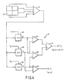
- Fig. 4 shows a quad detector and circuit for deriving two tracking signals from the servo data pits.
- Fig. 5 a-e show the two tracking signals derived from the servo data pits and a square wave signals generated from the second tracking signal useful in controlling the inversion of the damping signal.
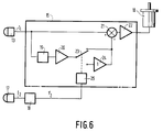
- Fig. 6 shows a detail of a fine servo system with inverted damping between tracks useful with the present invention.
- Fig. 7 shows the radial alignment of the servo data pits over a number of tracks.
- Fig. 8 shows a block diagram of the coarse servo's track crossing counter.
- Fig. 1 shows a preferred set of three servo data pits in a servo data area. Areas containing the pits are interspersed among areas containing data along a track. Track data areas in the preferred embodiment preferably do not include a preformatted groove, although such a groove having a depth of one-eighth wavelength of the laser read beam may be employed. Tracks over the whole disk can either be concentric or sprial, but when viewed only over the small portion of a given track or tracks as discussed herin, the tracks are substantially concentric. Areas containing servo data pits are radially aligned, track to track.
- the pits discussed herein are similarly preformatted pits and have the same size and shape; herein they are substantially circular and are one quarter wavelength deep.
- the invention herein contemplates the use of other forms of media alteration that would achieve substantially the same result as the pits discussed herein. While the areas containing the servo pits could have a shallow (less than one-twelfth wavelength) preformatted groove, they preferably have no groove at all because the groove interferes with the proper detection of the pits.
- a trailing pit B is aligned on the center of a track s. Spaced up the track a short distance from pit B are pits C and A offset from track center by one quarter of the track pitch of the optical disk, the track pitch being the radial distance between adjacent track centers.
- the pits are preferably spaced apart longitudinally as well. The pits should have at least 1.5 times the size of a pit between pits. Other arrangements for the pits are contemplated herein.
- Figure 2 shows one alternative example. Here, pit B leads pits A and C.
- Figure 3 shows the preferred optical disk drive.
- Laser 6, mounted in movable carriage 3 reflects a laser beam through polarizing beam splitter 7, quarterwave plate 11 and fine actuator 8 to disk 4 having the tracks and servo data pits formed thereon.
- the beam is reflected back through the splitter and an astigmatic lens 9 to a quad detector 110.
- This detector provides output signals which are summed in a servo signal generator 12.
- This detector and signal generator outputs the two tracking signals I1 and I t to both a fine servo 15 and a coarse servo and track crossing servo 16.
- the fine servo controls a motor 10 for controlling the fine actuator.
- the coarse servo controls a servo motor 18 which controls movement of carriage 3.
- Coarse servo is primarily used for track to track movement, especially during seek operations. (The elements, 12, 15 and 16 need not be mounted on the carriage 3.)
- Figure 4 shows the preferred tracking servo signal generator 12 for detecting the preferred pit arrangement and providing two radially varying sinuoidal disk drive servo systems. While a quad detector is shown herein, all elements are summed. This is equivalent to providing a single detector diode, as those skilled in the art will appreciate.
- a laser beam focused onto the disk with a spot small enough to detect the offset pits when centered on a track is directed to the optical disk and reflected carrying with it the light amplitude modulation caused by a pit.
- the signal of a pit is maximum when the beam is centered on a pit and minimum when the beam is one-half track offset from a pit (but radially aligned therewith and with an adjacent pit on the next track).
- the optics of the optical drive images the reflected beam onto to the detector 110.
- As the optics and laser beam pass pit B a Gaussian shaped signal appears out of summer 112.
- the signals caused by pits A and C out of the summer 112 when the beam spot is centered on a track are equal (including DC components) and when subtracted should result in a value of zero. This corresponds to the zero crossing of the sinusoidal signal.
- the signal caused by pit B on all four elements of the quad detector is maximized when the beam spot is centered on a track.
- a signal out of summer 112 caused by pit B would be 90 degrees out of phase with a difference signal from detecting pits C and A (in the radial direction).
- the signals from the four quadrants of the quad detector 110 are input to summing junction 112.
- the output of the summing junction is provided to three sample and holds 118, 126, and 128 which are enabled by timing signals T1-3 respectively.
- Timing signals T1-3 occur when a single servo data pit is imaged on the detector 110.
- T1 occurs when pit B is present.
- T2 occurs when pit A is present.
- T3 occurs when pit C is present.
- the preferred optical disk has a plurality of servo data pit areas along each track, interspersed with ordinary data.
- the servo data is preferably recorded with a defined relationship with conventional clocking data prerecorded on the disk such that the timing signals T1-3 can be provided by the same timing means used to sample ordinary data.
- the centered servo data pit can itself be used for timing.
- the data is recorded in a fixed block code and the servo data pits are recorded in a longitudinal relationship which violates the code and may be recognized therefor as servo data.
- pit B is used as a timing pit to synchonize a phase lock loop, which is refreshed at subsequent pit B's, and also controls the timing of sampling of the servo data pits (timing signals T1-3) and data (no prerecorded clock is needed in a preformatted groove).
- signal I1 the first tracking signal which is used for fine servo and its scaled derivative for damping. This signal is also used by the coarse servo 16 to determine track crossings.
- sample and hold 118 (pit B) is provided to the positive inputs of differential amplifiers 120 and 124, the negative inputs of which are provided by the outputs of sample and holds 126 (A) and 128 (C) respectively.
- the outputs of these two differential amplifiers are input to summing amplifier 114, the output of which comprises signal I t , the second tracking signal used to invert damping, determine track crossings, and in quadrature with the first tracking signal, track crossing direction.
- summing amplifier 114 the output of which comprises signal I t , the second tracking signal used to invert damping, determine track crossings, and in quadrature with the first tracking signal, track crossing direction.
- Figure 5 which is a copy '252's Figure 6, shows the radial relationship between signals I1 and I t and tracks s1 to s3. It can be seen that I1 and I t are both sinusoidal and offset by 90 degrees, the former having a zero crossing at track centers and the latter being negative between tracks, i.e. outside the boundaries comprising pits A and C.
- One signal can be denominated a sine signal and the other a cosine, to denote this phase relationship.
- the latter signal, I t is shaped by a square wave shaper in combination with a level detector (not shown herein, but described in 252') to form the square waves shown in Figures 5 c-e.
- the negative portions of these square waves shown in Figure 5 control signal to invert the damping in the fine servo.
- Figure 6 which is a copy of Figure 8 of '252.
- the damping derivative signal is inverted under control of solenoid 25 in combination with switch 23 and inverter 24 in response to the square wave from shaper 18, which is responsive to second tracking signal I t .
- the function of the circuit of Figure 6 is described fully in '252.
- data areas which may include a preformatted groove, follow the servo data area.
- FIG. 8 An exemplary coarse servo seek circuit is shown in Figure 8. This circuit counts the zero crossings of both signals I t and I1, of which there are four per track in a zero crossing track crossing pulse detectors 130 and 136, the outputs of which are divided by four and input to a track counter 134. This counter increments or decrements under control of direction output of quadrature detector 132, which determines the direction of movement from sine and cosine signals I1 and I t .
- the sine signal I1 is input to the clock input of a D flip flop 132, which triggers the D input to the Q output on a positive going transition, and the cosine signal is input to the D input.
- the state of the cosine signal (either 1 or -1) when the flip flop is clocked therefore depends upon which direction the track crossing is occurring.
Landscapes
- Optical Recording Or Reproduction (AREA)
- Moving Of The Head To Find And Align With The Track (AREA)
- Optical Record Carriers And Manufacture Thereof (AREA)
Claims (16)
- Disque optique (4) pourvu de pistes concentriques ou spirales comportant au moins une microcuvette centrée de données d'asservissement (B), centrée sur une piste, et au moins deux microcuvettes décalées de données d'asservissement (A, C) décalées de part et d'autre du centre de piste, lesdites microcuvettes ayant chacune la même taille et la même forme et étant voisines les unes des autres tout en étant séparées des données, caractérisé en ce que le décalage de la microcuvette de données d'asservissement correspond au quart du pas de piste, et en ce que les microcuvettes de données d'asservissement de pistes voisines sont radialement alignées, de telle manière que les microcuvettes centrées sont alignées avec les microcuvettes centrées et les microcuvettes décalées sont alignées avec les microcuvettes décalées correspondantes.
- Disque optique selon la revendication 1, dans lequel les microcuvettes de données d'asservissement sont enregistrées dans une zone de piste dépourvue d'une gorge préformatée.
- Disque optique selon la revendication 1 ou 2, dans lequel lesdites microcuvettes sont enregistrées dans des zones de données d'asservissement et une pluralité de telles zones sont enregistrées sur chaque piste de façon à être entremêlées de données.
- Disque optique selon la revendication 1, 2 ou 3, dans lequel ladite microcuvette centrée succède auxdites microcuvettes décalées.
- Disque optique selon l'une des revendications 1 à 4, dans lequel lesdites microcuvettes sont constituées chacune de trous préformatés d'une profondeur égale au quart de la longueur d'onde du faisceau laser.
- Disque optique selon l'une des revendications 1 à 5, dans lequel lesdites microcuvettes sont séparées dans le sens longitudinal d'au moins 1,5 fois la taille de chaque microcuvette.
- Disque optique selon l'une des revendications 1 à 6, dans lequel les données sont enregistrées sur lesdites pistes suivant un format de bloc fixe et lesdites microcuvettes sont enregistrées de manière qu'au moins l'une des trois microcuvettes n'a pas la relation de format de bloc fixe avec les autres microcuvettes.
- Disque optique selon la revendication 7, dans lequel lesdites microcuvettes sont enregistrées de manière que ladite microcuvette centrée soit séparée d'au moins une microcuvette décalée voisine par une distance plus grande que la distance déterminée par la relation de format de bloc fixe.
- Disque optique selon l'une des revendications 1 à 8, dans lequel des données sont enregistrées dans la piste, le format des données étant distinguable du format des microcuvettes des données d'asservissement.
- Dispositif d'entraînement de disque optique destiné à être utilisé en combinaison avec des disques optiques selon l'une des revendications 1 à 9, comportant des moyens (6) pour engendrer un faisceau laser, un système optique (7, 9, 11) pour diriger le faisceau laser vers un détecteur optique (110) via le disque optique, un générateur de signaux d'asservissement (12) couplé au détecteur optique pour déduire un premier signal de suivi de piste (I₁) d'un signal de sortie qui est délivré par le détecteur optique lorsque le faisceau de rayonnement explore les microcuvettes décalées, caractérisé par des moyens pour déduire un second signal de suivi de piste (It) d'un signal de sortie qui est délivré par le détecteur optique lorsque le faisceau laser explore les microcuvettes centrées, second signal de suivi de piste étant déphasé de 90° par rapport au premier signal de suivi de piste.
- Dispositif selon la revendication 10, dans lequel lesdits signaux d'asservissement des moyens générateurs comportent des moyens (116) pour soustraire le signal de sortie correspondant à l'exploration d'une première microcuvette décalée, du signal de sortie correspondant à l'exploration de la deuxième microcuvette décalée, pour engendrer le premier signal de suivi de piste (I₁).
- Dispositif selon la revendication 10 dans lequel ledit générateur de signaux d'asservissement comporte des moyens (120) pour soustraire le signal de sortie correspondant à l'exploration d'une première microcuvette décalée, du signal de sortie correspondant à l'exploration de la microcuvette centrée, des moyens (124) pour soustraire le signal correspondant à l'exploration de l'autre microcuvette décalée, du signal de sortie correspondant à l'exploration de la microcuvette centrée et des moyens (114) additionneurs des deux signaux soustraits pour former le second signal de suivi de piste (It).
- Dispositif selon la revendication 12, comportant en outre des moyens de système d'asservissement (19, 20) fonctionnant en réaction audit premier signal de suivi de piste, moyens qui comportent des moyens d'amortissement fonctionnant en réaction auxdits premiers moyens de suivi de piste et des moyens pour commander lesdits moyens d'amortissement en réaction audit second signal de suivi de piste.
- Dispositif selon la revendication 13, dans lequel lesdits moyens pour commander les moyens d'amortissement en réaction au second signal de suivi de piste comportent des moyens (23, 24, 25) pour inverser la sortie des moyens d'amortissement lorsqu'un faisceau laser du disque optique est centré en dehors des microcuvettes de données d'asservissement décalées, prévues entre les pistes.
- Dispositif selon la revendication 12, comportant en outre des moyens de système d'asservissement comportant des moyens détecteurs de direction à quatre quadrants (132) fonctionnant en réaction audit premier ainsi qu'audit second signal de suivi de piste pour déterminer la direction du mouvement de croisement de pistes.
- Appareil selon la revendication 15, comportant en outre des moyens (134) fonctionnant en réaction auxdits moyens détecteurs de direction à quatre quadrants et audit second signal de suivi de piste pour compter des pistes au cours d'opérations de recherche.
Applications Claiming Priority (2)
| Application Number | Priority Date | Filing Date | Title |
|---|---|---|---|
| US902278 | 1986-08-29 | ||
| US06/902,278 US4779253A (en) | 1985-07-30 | 1986-08-29 | Sampled servo for an optical disk drive |
Publications (3)
| Publication Number | Publication Date |
|---|---|
| EP0257703A2 EP0257703A2 (fr) | 1988-03-02 |
| EP0257703A3 EP0257703A3 (en) | 1990-01-24 |
| EP0257703B1 true EP0257703B1 (fr) | 1993-10-27 |
Family
ID=25415607
Family Applications (1)
| Application Number | Title | Priority Date | Filing Date |
|---|---|---|---|
| EP87201551A Expired - Lifetime EP0257703B1 (fr) | 1986-08-29 | 1987-08-17 | Disque optique et entraînement de disques optiques |
Country Status (6)
| Country | Link |
|---|---|
| US (1) | US4779253A (fr) |
| EP (1) | EP0257703B1 (fr) |
| JP (2) | JP2664689B2 (fr) |
| KR (1) | KR950011814B1 (fr) |
| AU (1) | AU606609B2 (fr) |
| DE (1) | DE3787940T2 (fr) |
Families Citing this family (32)
| Publication number | Priority date | Publication date | Assignee | Title |
|---|---|---|---|---|
| JPH0731813B2 (ja) * | 1987-02-27 | 1995-04-10 | 株式会社日立製作所 | 光デイスク |
| KR910008503B1 (ko) * | 1987-03-13 | 1991-10-18 | 미쯔비시덴끼 가부시끼가이샤 | 광 디스크 |
| US4855977A (en) * | 1987-07-27 | 1989-08-08 | Laser Magnetic Storage International Company | Track seeking apparatus and method using sampled information |
| JPH0721879B2 (ja) * | 1987-11-07 | 1995-03-08 | 株式会社日立製作所 | 光ディスク用レプリカ基盤,スタンパまたは原盤 |
| JPH01201832A (ja) * | 1988-02-04 | 1989-08-14 | Nakamichi Corp | 信号処理回路 |
| US5321675A (en) * | 1988-03-03 | 1994-06-14 | Mitsubishi Denki Kabushiki Kaisha | Pit spacing in the servo field of an optical disk for speed and direction detection and data retrieval |
| JPH0610879B2 (ja) * | 1988-07-08 | 1994-02-09 | シャープ株式会社 | 光メモリ装置 |
| JPH02130727A (ja) * | 1988-11-10 | 1990-05-18 | Sony Corp | ディスク状記録媒体 |
| US5272686A (en) * | 1988-11-14 | 1993-12-21 | Ricoh Company, Ltd. | Servo signal generator for optical disk driving apparatus |
| JP2731403B2 (ja) * | 1988-11-14 | 1998-03-25 | 株式会社リコー | 光ディスクドライブ装置 |
| JP2785290B2 (ja) * | 1988-12-19 | 1998-08-13 | ソニー株式会社 | 光ディスクのシーク及びトラッキング装置 |
| JP2741882B2 (ja) * | 1989-02-10 | 1998-04-22 | 株式会社日立製作所 | 光ディスク |
| CA2017229A1 (fr) * | 1989-06-30 | 1990-12-31 | James A. Cox | Element optique binaire pour tete d'enregistrement-lecture de disques optiques |
| JP2589814B2 (ja) * | 1989-07-19 | 1997-03-12 | 松下電器産業株式会社 | クロック抽出装置およびトラッキング誤差信号採取装置 |
| JPH03187027A (ja) * | 1989-12-15 | 1991-08-15 | Ricoh Co Ltd | トラッキングサーボ方法 |
| JPH03102485U (fr) * | 1990-02-08 | 1991-10-24 | ||
| US5214629A (en) * | 1990-02-27 | 1993-05-25 | Hitachi Maxell, Ltd. | Optical disc having a high-speed access capability and reading apparatus therefor |
| KR100254716B1 (ko) * | 1990-04-05 | 2000-05-01 | 이데이 노부유끼 | 광학식 디스크상의 정보기록 및 재생장치 |
| JP3507956B2 (ja) * | 1993-10-13 | 2004-03-15 | 株式会社日立製作所 | 光ディスク |
| JP2870127B2 (ja) * | 1990-05-31 | 1999-03-10 | ソニー株式会社 | トラッキング制御方法 |
| JP2793698B2 (ja) * | 1990-06-18 | 1998-09-03 | 株式会社リコー | フオーカスオフセット補正方法 |
| US5270991A (en) * | 1990-06-29 | 1993-12-14 | North American Philips Corporation | Track format for use with an optical record carrier having a varying track pitch |
| JPH0567375A (ja) * | 1990-08-07 | 1993-03-19 | Ricoh Co Ltd | 記録再生タイミング発生装置 |
| JPH04301219A (ja) * | 1991-03-28 | 1992-10-23 | Pioneer Electron Corp | 角速度一定型光ディスク及び角速度一定型光ディスクの倍密度記録方法 |
| US5404345A (en) * | 1991-06-07 | 1995-04-04 | Brother Kogyo Kabushiki Kaisha | Optical recording medium and tracking servo circuit adapted therefor using wobbled pits |
| DE69330232T2 (de) * | 1992-07-31 | 2002-01-10 | Matsushita Electric Industrial Co., Ltd. | Vorrichtung zur optischen Aufzeichnung/Wiedergabe von Daten |
| US5446716A (en) * | 1994-01-10 | 1995-08-29 | Eastman Kodak Company | Laser power control in an optical recording system to compensate for multiple system degradations |
| FI98976C (fi) * | 1994-07-11 | 1997-09-10 | Nokia Telecommunications Oy | Menetelmä kanavanvaihdon suorittamiseksi ja solukkoradiojärjestelmä |
| US5710753A (en) * | 1996-06-28 | 1998-01-20 | Eastman Kodak Company | Multi-element grating beam splitter using double refraction to reduce optical feedback and associated light source noise |
| US5677902A (en) * | 1996-06-28 | 1997-10-14 | Eastman Kodak Company | Beam splitter for optical recording |
| US6744711B1 (en) | 2000-06-20 | 2004-06-01 | Discovision Associates | Method and apparatus for a high-speed search of an optical medium |
| US7782726B2 (en) * | 2006-03-07 | 2010-08-24 | Marvell World Trade Ltd. | Write splice for optical recording channels |
Citations (1)
| Publication number | Priority date | Publication date | Assignee | Title |
|---|---|---|---|---|
| US760450A (en) * | 1903-12-04 | 1904-05-24 | Andy E Hall | Clothes-line reel and stretcher. |
Family Cites Families (25)
| Publication number | Priority date | Publication date | Assignee | Title |
|---|---|---|---|---|
| US3138669A (en) * | 1961-06-06 | 1964-06-23 | Rabinow Jacob | Record player using light transducer and servo |
| NL173343C (nl) * | 1972-03-29 | 1984-01-02 | Philips Nv | Inrichting voor het uitlezen van een schijfvormige registratiedrager met in optische vorm gecodeerde beeld-en/of geluidssignalen. |
| NL160138C (nl) * | 1972-05-11 | 1979-09-17 | Philips Nv | Inrichting voor het uitlezen van een vlakke registratie- drager. |
| US4037252A (en) * | 1973-11-10 | 1977-07-19 | U.S. Philips Corporation | Apparatus for reading a disc-shaped record carrier with plural scanning spots for stable radial tracking |
| US3881184A (en) * | 1974-05-28 | 1975-04-29 | Ibm | Adaptive digital servo system |
| GB1577133A (en) * | 1976-03-19 | 1980-10-22 | Rca Corp | Video information record and playback apparatus |
| JPS5371808A (en) * | 1976-12-08 | 1978-06-26 | Toshiba Corp | Optical information reader |
| US4151566A (en) * | 1977-11-29 | 1979-04-24 | Rca Corporation | Magnetic tape position measuring system |
| US4488275A (en) * | 1978-03-27 | 1984-12-11 | Discovision Associates | Tracking system for video disc player |
| US4195320A (en) * | 1978-05-15 | 1980-03-25 | International Business Machines Corporation | Record track identification and following |
| NL7808638A (nl) * | 1978-08-22 | 1980-02-26 | Philips Nv | Inrichting voor het uitlezen van een schijfvormige re- gistratiedrager. |
| US4257074A (en) * | 1979-06-15 | 1981-03-17 | Magnetic Peripherals Inc. | Time optimal function generator for disk file magnetic recording head servo position control loop |
| US4443870A (en) * | 1981-10-15 | 1984-04-17 | Burroughs Corporation | Optical memory system providing track following |
| FR2523347B1 (fr) * | 1982-03-12 | 1988-11-04 | Thomson Csf | Support d'information mobile pregrave et dispositif optique de suivi de piste mettant en oeuvre un tel support |
| FR2523349A1 (fr) * | 1982-03-12 | 1983-09-16 | Thomson Csf | Procede et dispositif optique de generation de signaux d'asservissements de la position d'une tache d'exploration des pistes d'un support d'information |
| US4456981A (en) * | 1982-03-19 | 1984-06-26 | Magnetic Peripherals Inc. | Modulation system for optical recording |
| JPS58220252A (ja) * | 1982-06-16 | 1983-12-21 | Hitachi Ltd | 光学式ピツクアツプのトラツキング誤差信号検出回路 |
| US4530079A (en) * | 1983-03-23 | 1985-07-16 | Xerox Corporation | Track following system for optical disc drive |
| EP0125019A1 (fr) * | 1983-04-05 | 1984-11-14 | Pioneer Electronic Corporation | Dispositif pour commander des opérations de saut de piste d'enregistrement |
| JPS60237644A (ja) * | 1984-05-11 | 1985-11-26 | Nippon Kogaku Kk <Nikon> | 情報再生装置 |
| FR2567673B1 (fr) * | 1984-07-10 | 1986-11-07 | Thomson Alcatel Gigadisc | Support d'information inscriptible optiquement selon une piste definie par des motifs de pregravure et dispositif optique de suivi de piste mettant en oeuvre un tel support |
| NL193159C (nl) * | 1985-06-19 | 1998-12-04 | Hitachi Ltd | Voorgevormde registratiedrager voor het daarin met behulp van een lichtvlek schrijven van informatie. |
| JP2702907B2 (ja) * | 1985-06-19 | 1998-01-26 | 株式会社日立製作所 | 情報記録媒体及びその記録再生装置 |
| ATE84631T1 (de) * | 1985-07-30 | 1993-01-15 | Philips Nv | Generatorkreis fuer spursignal und aufzeichnungstraeger dafuer. |
| US4677507A (en) * | 1986-05-30 | 1987-06-30 | Magnetic Peripherals Inc. | Digital velocity control for a disk drive servo system |
-
1986
- 1986-08-29 US US06/902,278 patent/US4779253A/en not_active Expired - Lifetime
-
1987
- 1987-08-17 DE DE87201551T patent/DE3787940T2/de not_active Expired - Lifetime
- 1987-08-17 EP EP87201551A patent/EP0257703B1/fr not_active Expired - Lifetime
- 1987-08-28 JP JP62213162A patent/JP2664689B2/ja not_active Expired - Lifetime
- 1987-08-28 AU AU77682/87A patent/AU606609B2/en not_active Expired
- 1987-08-29 KR KR1019870009493A patent/KR950011814B1/ko not_active Expired - Lifetime
-
1994
- 1994-05-30 JP JP6116575A patent/JP2799142B2/ja not_active Expired - Lifetime
Patent Citations (1)
| Publication number | Priority date | Publication date | Assignee | Title |
|---|---|---|---|---|
| US760450A (en) * | 1903-12-04 | 1904-05-24 | Andy E Hall | Clothes-line reel and stretcher. |
Also Published As
| Publication number | Publication date |
|---|---|
| JP2664689B2 (ja) | 1997-10-15 |
| US4779253A (en) | 1988-10-18 |
| DE3787940D1 (de) | 1993-12-02 |
| EP0257703A3 (en) | 1990-01-24 |
| JPS6390035A (ja) | 1988-04-20 |
| KR880003309A (ko) | 1988-05-16 |
| JP2799142B2 (ja) | 1998-09-17 |
| KR950011814B1 (ko) | 1995-10-10 |
| AU7768287A (en) | 1988-03-03 |
| AU606609B2 (en) | 1991-02-14 |
| JPH0773476A (ja) | 1995-03-17 |
| EP0257703A2 (fr) | 1988-03-02 |
| DE3787940T2 (de) | 1994-05-05 |
Similar Documents
| Publication | Publication Date | Title |
|---|---|---|
| EP0257703B1 (fr) | Disque optique et entraînement de disques optiques | |
| EP0530023B1 (fr) | Appareil pour l'enregistrement et la reproduction optique effectuant le suivi de pistes-guide ondulés | |
| US5034940A (en) | Information retrieval system with a tracking error threshold compensation of retrieved data and tracking error signals | |
| US4234837A (en) | Digital center tracking system | |
| KR900000019B1 (ko) | 광자기 디스크 장치 | |
| EP0453308A2 (fr) | Réduction des variations d'amplitude de signaux de lecture de disque optique | |
| JPH0528522A (ja) | 情報媒体のトラツク走査用光ビームのトラツキング制御信号発生方法及び装置 | |
| EP0191467B1 (fr) | Appareil à disque optique | |
| EP0270365A1 (fr) | Servocircuits pour appareils à enregistrer et/ou à reproduire des informations sur disque optique | |
| EP0422227A1 (fr) | Appareil d'enregistrement/reproduction sur disque optique | |
| EP0087973B1 (fr) | Système asservi de poursuite de piste pour appareil de reproduction d'information à disque optique | |
| JP3455298B2 (ja) | 光ビームの移動検出方法および光ディスク再生装置 | |
| EP0491573B1 (fr) | Lecteur de disque optique | |
| US5408452A (en) | Optical information recording/reproducing system including novel tracking system | |
| EP0117715B1 (fr) | Lecteur à disque optique | |
| EP0392775A2 (fr) | Système pour la détection d'erreur de suivi de piste dans un appareil d'enregistrement/reproduction optique | |
| JP2693608B2 (ja) | 情報記録ディスク演奏装置 | |
| JP2705676B2 (ja) | 光ディスク装置におけるアドレス検出装置 | |
| JPH04205922A (ja) | 光学情報記録再生装置 | |
| JPH041952B2 (fr) | ||
| JPH0198169A (ja) | トラック検索装置 | |
| JPH067415B2 (ja) | トラツク誤差検出方法 | |
| JPH06139575A (ja) | 光ディスク装置および光ディスク | |
| JPH041953B2 (fr) | ||
| JPH0518183B2 (fr) |
Legal Events
| Date | Code | Title | Description |
|---|---|---|---|
| PUAI | Public reference made under article 153(3) epc to a published international application that has entered the european phase |
Free format text: ORIGINAL CODE: 0009012 |
|
| AK | Designated contracting states |
Kind code of ref document: A2 Designated state(s): DE ES FR GB IT NL SE |
|
| PUAL | Search report despatched |
Free format text: ORIGINAL CODE: 0009013 |
|
| AK | Designated contracting states |
Kind code of ref document: A3 Designated state(s): DE ES FR GB IT NL SE |
|
| 17P | Request for examination filed |
Effective date: 19900719 |
|
| 17Q | First examination report despatched |
Effective date: 19920304 |
|
| RAP1 | Party data changed (applicant data changed or rights of an application transferred) |
Owner name: N.V. PHILIPS' GLOEILAMPENFABRIEKEN |
|
| GRAA | (expected) grant |
Free format text: ORIGINAL CODE: 0009210 |
|
| AK | Designated contracting states |
Kind code of ref document: B1 Designated state(s): DE ES FR GB IT NL SE |
|
| PG25 | Lapsed in a contracting state [announced via postgrant information from national office to epo] |
Ref country code: IT Free format text: LAPSE BECAUSE OF FAILURE TO SUBMIT A TRANSLATION OF THE DESCRIPTION OR TO PAY THE FEE WITHIN THE PRE;WARNING: LAPSES OF ITALIAN PATENTS WITH EFFECTIVE DATE BEFORE 2007 MAY HAVE OCCURRED AT ANY TIME BEFORE 2007. THE CORRECT EFFECTIVE DATE MAY BE DIFFERENT FROM THE ONE RECORDED.SCRIBED TIME-LIMIT Effective date: 19931027 Ref country code: SE Effective date: 19931027 Ref country code: NL Effective date: 19931027 |
|
| REF | Corresponds to: |
Ref document number: 3787940 Country of ref document: DE Date of ref document: 19931202 |
|
| ET | Fr: translation filed | ||
| PG25 | Lapsed in a contracting state [announced via postgrant information from national office to epo] |
Ref country code: ES Free format text: LAPSE BECAUSE OF FAILURE TO SUBMIT A TRANSLATION OF THE DESCRIPTION OR TO PAY THE FEE WITHIN THE PRESCRIBED TIME-LIMIT Effective date: 19940207 |
|
| NLV1 | Nl: lapsed or annulled due to failure to fulfill the requirements of art. 29p and 29m of the patents act | ||
| PLBE | No opposition filed within time limit |
Free format text: ORIGINAL CODE: 0009261 |
|
| STAA | Information on the status of an ep patent application or granted ep patent |
Free format text: STATUS: NO OPPOSITION FILED WITHIN TIME LIMIT |
|
| 26N | No opposition filed | ||
| REG | Reference to a national code |
Ref country code: FR Ref legal event code: CD |
|
| REG | Reference to a national code |
Ref country code: FR Ref legal event code: CD |
|
| REG | Reference to a national code |
Ref country code: GB Ref legal event code: IF02 |
|
| PGFP | Annual fee paid to national office [announced via postgrant information from national office to epo] |
Ref country code: FR Payment date: 20060828 Year of fee payment: 20 |
|
| PGFP | Annual fee paid to national office [announced via postgrant information from national office to epo] |
Ref country code: GB Payment date: 20060829 Year of fee payment: 20 |
|
| PGFP | Annual fee paid to national office [announced via postgrant information from national office to epo] |
Ref country code: DE Payment date: 20061013 Year of fee payment: 20 |
|
| REG | Reference to a national code |
Ref country code: GB Ref legal event code: PE20 |
|
| PG25 | Lapsed in a contracting state [announced via postgrant information from national office to epo] |
Ref country code: GB Free format text: LAPSE BECAUSE OF EXPIRATION OF PROTECTION Effective date: 20070816 |