EP0257808A2 - Sicherheitseinrichtung - Google Patents
Sicherheitseinrichtung Download PDFInfo
- Publication number
- EP0257808A2 EP0257808A2 EP87306635A EP87306635A EP0257808A2 EP 0257808 A2 EP0257808 A2 EP 0257808A2 EP 87306635 A EP87306635 A EP 87306635A EP 87306635 A EP87306635 A EP 87306635A EP 0257808 A2 EP0257808 A2 EP 0257808A2
- Authority
- EP
- European Patent Office
- Prior art keywords
- light
- arrangement
- token
- deflector
- receptor
- Prior art date
- Legal status (The legal status is an assumption and is not a legal conclusion. Google has not performed a legal analysis and makes no representation as to the accuracy of the status listed.)
- Withdrawn
Links
Images


Classifications
-
- E—FIXED CONSTRUCTIONS
- E05—LOCKS; KEYS; WINDOW OR DOOR FITTINGS; SAFES
- E05B—LOCKS; ACCESSORIES THEREFOR; HANDCUFFS
- E05B49/00—Electric permutation locks; Circuits therefor ; Mechanical aspects of electronic locks; Mechanical keys therefor
- E05B49/002—Keys with mechanical characteristics, e.g. notches, perforations, opaque marks
- E05B49/006—Keys with mechanical characteristics, e.g. notches, perforations, opaque marks actuating opto-electronic devices
-
- G—PHYSICS
- G06—COMPUTING OR CALCULATING; COUNTING
- G06K—GRAPHICAL DATA READING; PRESENTATION OF DATA; RECORD CARRIERS; HANDLING RECORD CARRIERS
- G06K19/00—Record carriers for use with machines and with at least a part designed to carry digital markings
- G06K19/06—Record carriers for use with machines and with at least a part designed to carry digital markings characterised by the kind of the digital marking, e.g. shape, nature, code
- G06K19/08—Record carriers for use with machines and with at least a part designed to carry digital markings characterised by the kind of the digital marking, e.g. shape, nature, code using markings of different kinds or more than one marking of the same kind in the same record carrier, e.g. one marking being sensed by optical and the other by magnetic means
- G06K19/10—Record carriers for use with machines and with at least a part designed to carry digital markings characterised by the kind of the digital marking, e.g. shape, nature, code using markings of different kinds or more than one marking of the same kind in the same record carrier, e.g. one marking being sensed by optical and the other by magnetic means at least one kind of marking being used for authentication, e.g. of credit or identity cards
- G06K19/16—Record carriers for use with machines and with at least a part designed to carry digital markings characterised by the kind of the digital marking, e.g. shape, nature, code using markings of different kinds or more than one marking of the same kind in the same record carrier, e.g. one marking being sensed by optical and the other by magnetic means at least one kind of marking being used for authentication, e.g. of credit or identity cards the marking being a hologram or diffraction grating
-
- G—PHYSICS
- G07—CHECKING-DEVICES
- G07F—COIN-FREED OR LIKE APPARATUS
- G07F7/00—Mechanisms actuated by objects other than coins to free or to actuate vending, hiring, coin or paper currency dispensing or refunding apparatus
- G07F7/08—Mechanisms actuated by objects other than coins to free or to actuate vending, hiring, coin or paper currency dispensing or refunding apparatus by coded identity card or credit card or other personal identification means
- G07F7/086—Mechanisms actuated by objects other than coins to free or to actuate vending, hiring, coin or paper currency dispensing or refunding apparatus by coded identity card or credit card or other personal identification means by passive credit-cards adapted therefor, e.g. constructive particularities to avoid counterfeiting, e.g. by inclusion of a physical or chemical security-layer
Definitions
- This invention relates to a security arrangement.
- the most common security arrangement currently used takes the form of a mechanical lock and key. Such an arrangement is not very secure unless it is very complex and expensive and even then it is rarely practicable to change the characteristics of the key without the need to fit a new lock. For example, if a key is lost without a duplicate being available, it is generally necessary to replace the entire lock. It is desirable to provide a security arrangement which is capable of being highly secure and for which the characteristics to which the lock responds can be easily and simply altered in order to preserve security over a long period of time.
- the present invention seeks to provide such a security arrangement.
- a security arrangement includes a token and a receptor, the token comprising a thin lamina carrying an optically readable pattern, and a thin holographic light deflector arranged to deflect light which is modified by said pattern; and the receptor comprising means for accepting the token and for detecting the deflected light.
- the arrangement may comprise not merely a conventional key and lock arrangement constituted by the token and the receptor respectively, but a more versatile security arrangement which could for example, form part of a larger transaction system with the token serving to provide access to those parts of the system which enable a transaction, possibly of a financial nature, to be performed.
- the thin lamina is preferably light transmissive and is arranged to carry the optically readable pattern and the holographic light deflector at its opposite major surfaces.
- the holographic light deflector may be arranged to produce a substantial degree of deflection of light and to bring the deflected light to at least an approximate focus at the position at which an optical sensor is located, or the holographic light deflector carried by the token may operate in conjunction with a further light deflector carried by the receptor in order to direct the light onto an optical sensor.
- the further light deflector takes the form of a thin holographic deflector, which in operation is adjacent to the first mentioned holographic deflector.
- the first deflector is preferably arranged to "scramble" the light incident upon it, and the further light deflector provides a complementary action.
- the optical pattern can take the form of a complex bar code having many possible combinations, typically well in excess of one million.
- it is not sufficient merely to duplicate the particular code which is carried by token, as the coded light will not reach the optical sensor unless it is correctly directed thereto by the holographic deflector.
- the holographic deflector is itself of negligible thickness, it can be incorporated as a thin film at the surface of the token.
- Such a hologram is very difficult to reproduce from a sample of a token, particularly as its optical response will depend on the nature of the optical properties of the lamina itself and on any external protective coating which is applied to it.
- each token incorporates an optical pattern, e.g. a bar code. Removal of the layer of the token which incorporates the bar code within it will alter the optical properties of the deflection produced by a substantial amount such that the light will no longer be detected by the optical sensor forming part of the receptor. Furthermore, in those security arrangements in which the two complementary holographic deflectors are present, no useful information as to the optical nature of the receptor can be derived from an examination of the token alone.
- a different holographic deflector can be incorporated into the token.
- each hotel could utilise a different hologram.
- a number of different holograms could be used for vehicles of a different manufacture or model. Since each application could have a relatively few number of tokens associated with a particular hologram, it would be unproductive to perform the very expensive and critical process necessary to replicate a particular hologram if the end result has only a very limited usage.
- One way in which the security of the arrangement can be enhanced is to provide the receptor with a very narrow slot in which an inserted token is a very close fit. This ensures that the thin film holographic deflector could not be replaced by the real optical arrangement which it simulates. Thus if the holographic deflector produces a marked angular deflection of light passing through it, the equivalent optical lens or prism would be relatively bulky and could not be inserted through the very thin slot designed to accept only thickness of a thin card-like token.
- the token could incorporate a reflective surface at one face so that the optical sensor is positioned on the same side of the token as a source of light which illuminates the optical pattern.
- a reflective surface at one face so that the optical sensor is positioned on the same side of the token as a source of light which illuminates the optical pattern.
- a token 1 takes the form of a very thin rectangular lamina or sheet 2 of transparent plastics material having a slightly thicker opaque handle portion 3.
- This token 1 carries an optically readable pattern at one surface 4 and a holographic deflector at its other surface 5.
- the nature of the optically readable pattern is illustrated in Figure 2 and it will be seen that it consists of five elongate stripes 6, 7, 8,9 and 10 carrying bar code segments disposed along their length. In this instance, eight bar code segments are disposed along each stripe, and as the five stripes are provided, an extremely large number of different combinations of code can be achieved.
- token 1 is shown inserted within a light-tight housing 11 having a light source 12 positioned adjacent to the surface 4 and having a solid block of light transmissive material 13 positioned adjacent to the surface 5, with an optical sensor 14 being mounted within the material 13 but offset to the rear surface of the housing 11.
- the light source 12 consists of eight discrete light sources, each of which takes the form of an elongate vertical strip 15 to 22 of illumination. In operation, each light source is energised in turn and the resulting light passes through the bar codes and is deflected towards the light sensor 14. Although illustrated as a single sensor 14 it in fact consists of five separate detectors spaced vertically apart so that each detector is associated with a different one of the bar code stripes 6 to 10. In this example, the bar code consists of transparent and opaque segments, but instead the segments could exhibit optical polarisation properties for example.
- the token 1 is inserted into the housing 11 of the receptor so that the optical pattern is correctly positioned with respect to the light source 12, and the handle portion 3 serves to exclude external light.
- the light sources are automatically energised in turn by switch means (not shown) such that each of the five detectors of the optical sensor 14 receives light corresponding to the different segments of each bar code.
- the holographic deflector which is incorporated into the material of the token 1 at its surface 5 simulates an optical lens and serves to accurately deflect and focus the light on to the detectors.
- the inner surface of the housing 11 is coated with a light absorptive material such that light does not reach the detectors by virtue of specular reflection.
- optically transmissive material 13 within the housing 11 enables the optical properties of the system as a whole to be more precisely controlled, and part of it can contribute a lens which is operable in combination with the holographic deflector to direct the light to the light source 14.
- the optical properties of the holographic deflector are not such as to bring the light to a focus at the light sensor.
- the optical pattern is formed at the outer surface of the optically transparent lamina 2 in the form of a series of opaque segments 23.
- the holographic deflector 24 is formed as a very thin embossed film. This film is produced by stamping a die derived from a master impression and is then attached by means of suitable adhesive to the surface of the lamina 2.
- the whole of the lamina 2, including the deflector 24 and the code segments 23, is then encapsulated in a thin transparent protective plastics coating 25 which has optical properties, such as refractive index and colour, which correspond as closely as possible to those of the lamina 2.
- each of the constituent parts of the token would be made of an appropriate form of inert plastics material,
- Figure 4 shows an embodiment which is similar to that of Figure 1, but in this instance two thin film holographic deflectors 40 and 41 are provided, deflector 40 being embedded in the surface of the token 1, and the other deflector 41 being mounted at the surface of the material 13.
- the action of deflector 40 is to scramble and deflect the light so that at its outer surface the light represents random variations in intensity and direction.
- the action of deflector 41 is complementary in that it gathers this random light, and re-directs it in an ordered manner so that it is brought to a focus at the light sensor 14.
- the merit of this particular arrangement is that the optical properties of the token cannot be readily deduced from an examination of the hologram which it carries.
- the holographic deflector 41 can be such as to direct light to different positions within the housing, depending on the position chosen for the light sensor 14.
- different pairs of deflectors can all be such as to bring light to a predetermined focal point within the housing, with a particular deflector 41 being allocated to a particular hotel or model of car, etc.
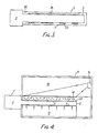
- FIG. 5 An alternative embodiment is shown in Figure 5 in which a token 30 is used by placing it upon an upper surface 31 of a receptor 32.
- the actual mode of operation and structure are very similar in principle to that already described with reference to Figure 1, except that the light source 12 is now placed on the same side of the token 30 as the light sensor 14, and this is made possible by the provision of an external reflector 33 which is attached to one surface of the token.
- a directional light transmissive plate 34 is mounted in front of the source 12. This consists of a matrix of apertures extending through the thickness of the plate so that the light from the source 12 is visible only in the straight ahead position.
- a raised rim 35 indicates to a user the position in which the token should be placed on the upper surface 31.
- a sensor 14 which responds to infra-red or ultra-violet light.
- the window 37 which is surrounded by the rim 35 is not transparent to visible light, but only to that light to which the sensor 14 is sensitive. Thus to a user of the system, the window 37 appears to be opaque and the internal construction is not visible.
- the entire token can be coated with material which is opaque to visible light, so that neither the bar code nor the presence of the holographic deflector can be seen.
Landscapes
- Physics & Mathematics (AREA)
- General Physics & Mathematics (AREA)
- Engineering & Computer Science (AREA)
- Theoretical Computer Science (AREA)
- Computer Security & Cryptography (AREA)
- Lock And Its Accessories (AREA)
- Mechanical Optical Scanning Systems (AREA)
- Diffracting Gratings Or Hologram Optical Elements (AREA)
- Holo Graphy (AREA)
Applications Claiming Priority (2)
| Application Number | Priority Date | Filing Date | Title |
|---|---|---|---|
| GB8619286A GB2193591B (en) | 1986-08-07 | 1986-08-07 | Security arrangement |
| GB8619286 | 1986-08-07 |
Publications (2)
| Publication Number | Publication Date |
|---|---|
| EP0257808A2 true EP0257808A2 (de) | 1988-03-02 |
| EP0257808A3 EP0257808A3 (en) | 1989-06-14 |
Family
ID=10602371
Family Applications (1)
| Application Number | Title | Priority Date | Filing Date |
|---|---|---|---|
| EP87306635A Withdrawn EP0257808A3 (en) | 1986-08-07 | 1987-07-28 | Security arrangement |
Country Status (5)
| Country | Link |
|---|---|
| US (1) | US4837425A (de) |
| EP (1) | EP0257808A3 (de) |
| JP (1) | JPS6367387A (de) |
| AU (1) | AU7661587A (de) |
| GB (1) | GB2193591B (de) |
Cited By (5)
| Publication number | Priority date | Publication date | Assignee | Title |
|---|---|---|---|---|
| EP0337921A3 (en) * | 1988-04-09 | 1990-12-05 | Ewald Rollnik | Assembly for recognizing and securing objects and its application |
| WO1992001975A1 (en) * | 1990-07-16 | 1992-02-06 | D.A.H.T. Foundation | Method of identifying a hologram and device for carrying out said method |
| EP0623722A1 (de) * | 1993-05-03 | 1994-11-09 | PARMA ANTONIO & FIGLI S.p.A. | Holographische Sicherheitsschliessvorrichtung |
| WO1995001614A1 (en) * | 1993-07-02 | 1995-01-12 | O.S.C. Oto Sistemi Civili Azienda Della Gf-Oto Melara Breda Bresciana S.R.L. | Optoelectronic apparatus and relevant method for the automatic check of authenticity of documents and objects by means of holograms |
| WO1997009209A3 (en) * | 1995-09-01 | 1997-07-03 | United Technologies Automotive | Optical anti-theft system |
Families Citing this family (14)
| Publication number | Priority date | Publication date | Assignee | Title |
|---|---|---|---|---|
| US5367148A (en) * | 1986-04-18 | 1994-11-22 | Cias, Inc. | Counterfeit detection using ID numbers with at least one random portion |
| EP0366858B1 (de) * | 1988-09-30 | 1995-08-02 | Landis & Gyr Technology Innovation AG | Strichkodefeld und Strichkodeleser |
| US5046841A (en) * | 1989-01-19 | 1991-09-10 | Idx, Inc. | Token having a predetermined optical characteristic, and a token validation device for use therewith |
| US5003600A (en) * | 1989-08-03 | 1991-03-26 | The United States Of America As Represented By The Department Of Energy | Diffraction gratings used as identifying markers |
| EP0506680B1 (de) * | 1989-10-11 | 1997-12-29 | Cias Inc. | Kode und vorrichtung für optimale fehlerdetektion und -verbesserung |
| EP0587669A4 (de) * | 1991-06-05 | 1995-02-22 | Mikoh Pty Ltd | Brechungsgitter enthaltende, optische speicher. |
| US5283431A (en) * | 1992-02-04 | 1994-02-01 | Rhine Raymond J | Optical key security access system |
| US6086706A (en) * | 1993-12-20 | 2000-07-11 | Lucent Technologies Inc. | Document copying deterrent method |
| US5593017A (en) * | 1994-03-18 | 1997-01-14 | Environmental Products Corporation | Method and apparatus for identifying information contained in surface deviations |
| NL9400782A (nl) * | 1994-05-11 | 1995-12-01 | Unicate Bv | Aftastinrichting. |
| US6280326B1 (en) | 1997-06-24 | 2001-08-28 | Mikohn Gaming Corporation | Cashless method for a gaming system |
| DE10225375B4 (de) * | 2002-06-06 | 2004-06-09 | Codixx Ag | Optisches Sicherheitssystem |
| US6908035B2 (en) * | 2003-03-18 | 2005-06-21 | Eastman Kodak Company | Optical security system |
| US20160026275A1 (en) * | 2014-07-23 | 2016-01-28 | Verifone, Inc. | Data device including ofn functionality |
Family Cites Families (6)
| Publication number | Priority date | Publication date | Assignee | Title |
|---|---|---|---|---|
| US4464566A (en) * | 1970-09-21 | 1984-08-07 | Daniel Silverman | Access security control |
| DE2451732A1 (de) * | 1974-10-31 | 1976-05-06 | Unitec Gmbh & Co Kg | Identitaetstraeger und lesegeraet dafuer |
| DE2648180C2 (de) * | 1976-02-18 | 1978-09-07 | Hoechst Ag, 6000 Frankfurt | Vorrichtung zur Echtheitsprüfung eines Identitätsträgers |
| US4179686A (en) * | 1976-11-03 | 1979-12-18 | Bonicalzi Maria P | System for checking the authenticity of identification papers |
| US4108367A (en) * | 1977-02-25 | 1978-08-22 | Rca Corporation | Token and reader for vending machines |
| EP0032369A1 (de) * | 1980-01-10 | 1981-07-22 | Zeag Systems AG | Informationsträger für maschinell lesbare Informationen |
-
1986
- 1986-08-07 GB GB8619286A patent/GB2193591B/en not_active Expired - Lifetime
-
1987
- 1987-07-28 EP EP87306635A patent/EP0257808A3/en not_active Withdrawn
- 1987-07-31 US US07/080,499 patent/US4837425A/en not_active Expired - Fee Related
- 1987-08-06 JP JP62197243A patent/JPS6367387A/ja active Pending
- 1987-08-06 AU AU76615/87A patent/AU7661587A/en not_active Abandoned
Cited By (6)
| Publication number | Priority date | Publication date | Assignee | Title |
|---|---|---|---|---|
| EP0337921A3 (en) * | 1988-04-09 | 1990-12-05 | Ewald Rollnik | Assembly for recognizing and securing objects and its application |
| WO1992001975A1 (en) * | 1990-07-16 | 1992-02-06 | D.A.H.T. Foundation | Method of identifying a hologram and device for carrying out said method |
| EP0623722A1 (de) * | 1993-05-03 | 1994-11-09 | PARMA ANTONIO & FIGLI S.p.A. | Holographische Sicherheitsschliessvorrichtung |
| WO1995001614A1 (en) * | 1993-07-02 | 1995-01-12 | O.S.C. Oto Sistemi Civili Azienda Della Gf-Oto Melara Breda Bresciana S.R.L. | Optoelectronic apparatus and relevant method for the automatic check of authenticity of documents and objects by means of holograms |
| WO1997009209A3 (en) * | 1995-09-01 | 1997-07-03 | United Technologies Automotive | Optical anti-theft system |
| US5745045A (en) * | 1995-09-01 | 1998-04-28 | United Technologies Automotive, Inc. | Optical anti-theft system |
Also Published As
| Publication number | Publication date |
|---|---|
| JPS6367387A (ja) | 1988-03-26 |
| AU7661587A (en) | 1988-02-11 |
| GB8619286D0 (en) | 1986-10-15 |
| US4837425A (en) | 1989-06-06 |
| GB2193591A (en) | 1988-02-10 |
| GB2193591B (en) | 1990-07-25 |
| EP0257808A3 (en) | 1989-06-14 |
Similar Documents
| Publication | Publication Date | Title |
|---|---|---|
| US4837425A (en) | Security arrangement | |
| US4034211A (en) | System and method for providing a security check on a credit card | |
| AU584035B2 (en) | Holographic security devices and systems | |
| US6446865B1 (en) | Reflective badge security identification system | |
| US5138468A (en) | Keyless holographic lock | |
| CA1097107A (en) | Optical image comparison device for identification verification | |
| US4921278A (en) | Identification system using computer generated moire | |
| EP0251253B1 (de) | Sicherheitsdokument | |
| US5633975A (en) | Security system responsive to optical fiber having Bragg grating | |
| US4641017A (en) | Fraud resistant credit card system | |
| JPS6046470B2 (ja) | 光学読取り装置 | |
| GB2221870A (en) | Security device | |
| EP0866420A2 (de) | Ausweiskarte oder Namensschild | |
| US4204638A (en) | Process of coding a card with a diffraction grating having lines with irregular spacing | |
| WO1992004692A1 (en) | Security device | |
| US7407101B2 (en) | Card with enhanced security features | |
| US3858031A (en) | Credit card having clear middle layer encoded by discrete opaque areas and system for decoding same by laser beam | |
| EP1049962A1 (de) | System zur überprüfung von identifikationskarten | |
| EP0138525B1 (de) | Optisches Lesegerät zum Lesen von einer Ausweisschlüsselkarte | |
| US3629835A (en) | Credit card validation system using an optical reader employing reflected light | |
| JPH08263841A (ja) | 光学的機械的に読み取り可能な情報保持体 | |
| US4362930A (en) | Data carrier card | |
| RU2023126C1 (ru) | Запорное предохранительное устройство | |
| GB2106832A (en) | Telephone debit card | |
| RU2115168C1 (ru) | Способ идентификации объекта и идентификационная метка |
Legal Events
| Date | Code | Title | Description |
|---|---|---|---|
| PUAI | Public reference made under article 153(3) epc to a published international application that has entered the european phase |
Free format text: ORIGINAL CODE: 0009012 |
|
| AK | Designated contracting states |
Kind code of ref document: A2 Designated state(s): AT BE CH DE ES FR GR IT LI LU NL SE |
|
| PUAL | Search report despatched |
Free format text: ORIGINAL CODE: 0009013 |
|
| AK | Designated contracting states |
Kind code of ref document: A3 Designated state(s): AT BE CH DE ES FR GR IT LI LU NL SE |
|
| 17P | Request for examination filed |
Effective date: 19891204 |
|
| STAA | Information on the status of an ep patent application or granted ep patent |
Free format text: STATUS: THE APPLICATION IS DEEMED TO BE WITHDRAWN |
|
| 18D | Application deemed to be withdrawn |
Effective date: 19920201 |
|
| RIN1 | Information on inventor provided before grant (corrected) |
Inventor name: EDWARDS, PHILIP JULIAN |