EP0257931A1 - Distributeur pour liquide, en particulier pour distribuer un fluide de correction - Google Patents
Distributeur pour liquide, en particulier pour distribuer un fluide de correction Download PDFInfo
- Publication number
- EP0257931A1 EP0257931A1 EP87307185A EP87307185A EP0257931A1 EP 0257931 A1 EP0257931 A1 EP 0257931A1 EP 87307185 A EP87307185 A EP 87307185A EP 87307185 A EP87307185 A EP 87307185A EP 0257931 A1 EP0257931 A1 EP 0257931A1
- Authority
- EP
- European Patent Office
- Prior art keywords
- barrel
- air inlet
- fluid
- dispenser
- outlet
- Prior art date
- Legal status (The legal status is an assumption and is not a legal conclusion. Google has not performed a legal analysis and makes no representation as to the accuracy of the status listed.)
- Withdrawn
Links
- 239000002989 correction material Substances 0.000 title description 6
- 239000007788 liquid Substances 0.000 title description 5
- 239000012530 fluid Substances 0.000 claims abstract description 47
- 238000005096 rolling process Methods 0.000 claims abstract 5
- 238000004891 communication Methods 0.000 claims description 4
- 238000013022 venting Methods 0.000 abstract 1
- 239000000463 material Substances 0.000 description 8
- 239000002991 molded plastic Substances 0.000 description 6
- 239000000049 pigment Substances 0.000 description 4
- 230000007246 mechanism Effects 0.000 description 3
- 230000000717 retained effect Effects 0.000 description 3
- 238000007789 sealing Methods 0.000 description 3
- 239000002904 solvent Substances 0.000 description 3
- 239000011248 coating agent Substances 0.000 description 2
- 238000000576 coating method Methods 0.000 description 2
- 239000006260 foam Substances 0.000 description 2
- 238000004519 manufacturing process Methods 0.000 description 2
- 239000004033 plastic Substances 0.000 description 2
- 229920003023 plastic Polymers 0.000 description 2
- 238000005086 pumping Methods 0.000 description 2
- 239000011347 resin Substances 0.000 description 2
- 229920005989 resin Polymers 0.000 description 2
- 239000000725 suspension Substances 0.000 description 2
- 238000009825 accumulation Methods 0.000 description 1
- 238000013019 agitation Methods 0.000 description 1
- 230000000903 blocking effect Effects 0.000 description 1
- 230000006835 compression Effects 0.000 description 1
- 238000007906 compression Methods 0.000 description 1
- 230000001276 controlling effect Effects 0.000 description 1
- 239000006185 dispersion Substances 0.000 description 1
- 238000001035 drying Methods 0.000 description 1
- 230000000694 effects Effects 0.000 description 1
- 230000005484 gravity Effects 0.000 description 1
- 239000004615 ingredient Substances 0.000 description 1
- 239000002184 metal Substances 0.000 description 1
- 230000002093 peripheral effect Effects 0.000 description 1
- 239000011148 porous material Substances 0.000 description 1
- 230000002035 prolonged effect Effects 0.000 description 1
- 230000001105 regulatory effect Effects 0.000 description 1
- 238000009877 rendering Methods 0.000 description 1
- 239000003381 stabilizer Substances 0.000 description 1
- 210000003813 thumb Anatomy 0.000 description 1
- 239000007966 viscous suspension Substances 0.000 description 1
- 239000000080 wetting agent Substances 0.000 description 1
Images

Classifications
-
- B—PERFORMING OPERATIONS; TRANSPORTING
- B43—WRITING OR DRAWING IMPLEMENTS; BUREAU ACCESSORIES
- B43K—IMPLEMENTS FOR WRITING OR DRAWING
- B43K5/00—Pens with ink reservoirs in holders, e.g. fountain-pens
- B43K5/18—Arrangements for feeding the ink to the nibs
- B43K5/1818—Mechanical feeding means, e.g. valves; Pumps
- B43K5/1827—Valves
- B43K5/1836—Valves automatically closing
- B43K5/1845—Valves automatically closing opened by actuation of the writing point
-
- B—PERFORMING OPERATIONS; TRANSPORTING
- B43—WRITING OR DRAWING IMPLEMENTS; BUREAU ACCESSORIES
- B43K—IMPLEMENTS FOR WRITING OR DRAWING
- B43K7/00—Ball-point pens
- B43K7/02—Ink reservoirs; Ink cartridges
- B43K7/08—Preventing leakage
-
- B—PERFORMING OPERATIONS; TRANSPORTING
- B43—WRITING OR DRAWING IMPLEMENTS; BUREAU ACCESSORIES
- B43L—ARTICLES FOR WRITING OR DRAWING UPON; WRITING OR DRAWING AIDS; ACCESSORIES FOR WRITING OR DRAWING
- B43L19/00—Erasers, rubbers, or erasing devices; Holders therefor
- B43L19/0018—Erasers, rubbers, or erasing devices; Holders therefor with fluids
Definitions
- This invention relates to a dispenser implement, particularly although not exclusively, in the form of a writing or marking implement or pen for dispensing correction fluid.
- a quick drying correction fluid comprising a particulate pigment dispersed in a volatile liquid medium.
- the requirement with such a pen is that it should be capable of dispensing a carefully regulated flow of fluid when a correction is to be made, yet leakage of fluid should be effectively prevented when the pen is not in use.
- a relatively narrow nib outlet is provided and air admission to the interior of the barrel to replace dispensed fluid may be controlled or restricted.
- the nib may be in the form of a capillary tube and a pressurised system may be used whereby prior to dispense a pump mechanism is operated, e.g. by repeatedly pressing a button at the opposite end of the barrel to the nib, to increase the pressure of air within the barrel.
- a pump mechanism e.g. by repeatedly pressing a button at the opposite end of the barrel to the nib, to increase the pressure of air within the barrel.
- the wire itself may be a source of problems in that accumulation of dried material may form around the wire and block the capillary.
- the correction fluid settles out rapidly and it is desirable to accommodate ball bearings within the barrel which act to re-disperse settled material when the pen is shaken.
- the presence of the wire may make it difficult to accommodate such ball bearings or to allow contact with deposits in the region of the outlet to the nib.
- the pen can be difficult or inconvenient to manufacture having regard to the requisite high tolerances of the diameters of the wire and the capillary tube bearing in mind that the differences in such diameters may be of the order of 0.05mm.
- An object of the present invention is to provide a dispenser implement which is simple and convenient to manufacture and with which it is possible to achieve continuous dispense in a satisfactory manner using fluids of a wide range of viscosities.
- a dispenser implement comprising a barrel providing a reservoir for fluid to be dispensed, a dispense outlet in communication with the reservoir at one end of the barrel. a valve for controlling flow of fluid through said outlet, said valve being normally biased to a closed position, and an openable and closable air inlet in communication with the reservoir, said inlet being openable to permit free admission of air from the atmosphere to the reservoir, and said valve being movable to an open position independently of the opening of said air inlet.
- the air inlet may be at the opposite end of the barrel to the dispense outlet and a detachable cap or plug member may be provided for opening and closing the inlet.
- a porous fluid restricting element such as a pad of foam plastics or the like, may be provided across the inlet to restrict or prevent inadvertent outflow of fluid when the inlet is open.
- the valve comprises an elongate valve member which extends through and externally of the outlet and is axially spring biased to a position at which it engages a valve seat around the outlet thereby to seal same, opening of the valve being effected by pushing the valve member axially inwardly so as to clear the seat, and in particular this opening of the valve may be arranged to occur when the outlet end of the dispenser is pressed onto a surface onto which the fluid is required to be dispensed.
- the valve member may be a rod which is tapered towards the outer end thereof so that the periphery of the rod is spring urged tightly into engagement with a circular valve seat around the outlet, which valve seat may be appropriately shaped or covered or otherwise formed to give good contact with the valve member.
- the valve member may be biased to the closed position by means of a spiral spring.
- the valve member and the spiral spring may be formed integrally e.g. as a moulded plastics part.
- the dispenser may be in the form of a hand-held pen, and a cap may be provided to fit tightly over the outlet end of the barrel when the pen is not in use.
- the dispenser may be used for dispensing a correction fluid e.g. consisting of a dispersion of a finely divided pigment in a volatile solvent containing a dissolved coating resin and auxiliary ingredients such as suspension stabilisers and wetting agents may also be included.
- a correction fluid e.g. consisting of a dispersion of a finely divided pigment in a volatile solvent containing a dissolved coating resin and auxiliary ingredients such as suspension stabilisers and wetting agents may also be included.
- the dispenser implement shown in Figure 1 is in the form of a hand-held pen and comprises a tubular barrel 1 of circular cross section. At a rear end of th barrel has a dome-shaped end 2 which is closed exept for a small central hole 3. On the inside of the end 2 there are projecting prongs 4 and a disc 5 of porous material such as a dense foam plastics material is held in position on the prongs 4 over the hole 3. On the outside there is a peripheral rim 6 and an integrally formed cap 7 which can be pivoted, about a hinge joint 8, between a closed position as shown in which a central spike 9 engages and seals the hole 3, and an open position at which the hole 3 is freely open to the atmosphere.
- a hollow tapered end piece 10 which is held in position by interengagement of screw threads 11.
- the end piece 10 tapers to a narrow outlet opening 12 which is bounded by a circular edge 13.
- a valve member comprising a conically tapered moulded plastics rod 14 which extends at its smaller diameter end through the opening 12.
- a moulded plastics spiral spring 15 At its larger diameter end it is formed integrally with one end of a moulded plastics spiral spring 15.
- the other end of the spring 15 bears against the adjacent end of the barrel 1 and is too wide to enter the barrel.
- the spring 15 normally urges the rod 14 to a position at which it fits tightly within the circular edge 13 thereby to seal the opening 12.
- a push-fit cap 16 is provided which fits around the end piece 10 onto the end of the end piece 10 adjacent the barrel 1.
- the barrel 1 is filled with correcting fluid of a conventional kind comprising a viscous suspension of a pigment in a solution of a resin in a volatile solvent.
- correcting fluid of a conventional kind comprising a viscous suspension of a pigment in a solution of a resin in a volatile solvent.
- Two ball bearings 17 are inserted into the barrel 1 and the end piece 10 is screwed into position.
- the suspension in the barrel 1 is first agitated by shaking the pen. It will be noted that the interior of the barrel 1 is relatively free of crevices and projecting parts whereby the ball bearings 17 can freely move around and readily disturb any deposits of settled pigment.
- the pen is then turned upright with the rear end uppermost and the cap 7 is opened.
- the cap 16 is removed and the projecting tip of the rod 14 is pressed onto a surface to which correction fluid is to be dispensed. This causes the rod 14 to move upwardly against the spring 15 whereby fluid flows out of the outlet 12 onto the surface.
- the arrangement of the cap 7 gives good exposure to the atmosphere when required to facilitate prolonged continuous flow yet this is achieved without use of mechanisms which intrude into the barrel 1.
- the pad 5 prevents inadvertent loss of fluid e.g. if the pen is shaken with the cap 7 open.
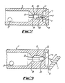
- the device as shown in Figures 2 + 3 may be provided for the purpose of preventing the inadvertent loss of fluid if the pen is shaken with the cap 7 open.
- the barrel 1 is provided at the end 2 with three or some other suitable number, of internal ribs 18.
- the ribs 18 are formed having a lip 19 at their forward ends so as to retain a third ball bearing 20 in the space 21 at the end 2 of the barrel 1.
- the ball bearing 20 is of the same diameter as the ball bearings 17 so that the number of differing parts of the pen is kept to a mimimum.
- each rib 18 At the other end of each rib 18 is formed a wedge surface 22 whereby the ball bearing 20 may be held captive in the tapering socket space formed between the three wedge surfaces 22.
- the spike 9 prevents the ball bearing 20 from being retained by the wedge surfaces 22 so that it may freely move within the space 21 as the pen is shaken, as shown in Figure 2.
- the cap 7 is left open as shown in Figure 3, then on the commencement of shaking the pen, or if the pen is tilted upside down, the ball bearing 20 will move in space 21 and be engaged and retained by the wedge surfaces 22, thereby closing the hole 3 and preventing leakage of the fluid. Closing the cap 7 will disengage the ball bearing 20 from the wedge surfaces 22.
- the length of the ribs 18 is such that the movement of the ball bearing 20 is restricted to approximately 1mm, sufficient to agitate the fluid in the barrel 1.
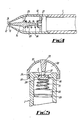
- the barrel 1 has a hollow tapered end piece 10 secured thereto as a push fit, or by screw threads as in the embodiment of Figure 1.
- the end piece 10 has a narrow outlet opening 12 bonded by a circular edge 13.
- a valve member comprising a moulded plastics rod 14 conically tapered towards its ends from a central part having a radial flange 23 therearound.
- One tip end 24 of the rod 14 fits tightly within the circular edge 13 to seal the opening 12 when the dispenser is not in use.
- the other end 25 has a soft metal compression spring 26 located thereon, one end of which bears against the flange 23 and the other end of which bears against an annular spring support 27 which is a push fit within the end piece 10.
- the integrally moulded plastics material spring 15 may not be soft enough to give good application pressure without damage to the surface to which the dispensed fluid is to be applied. However if the spring is too soft proper sealing of the orifice 12 will not occur. In such circumstances the embodiment of Figure 4 as described above may provide a more acceptable working dispenser.
- FIG. 5 there is shown an alternative embodiment of the "rear" end of dispensing implement, in which any risk of leakage of fluid when the implements as described in relation to Figures 1 to 3 are used, such as might occur when those embodiments are shaken or laid down with the flap inadvertently left open, is reduced even further.
- the barrel 1 is closed at the end except for a central hole 3 forming a seating for a conical valve member 28, the end of the barrel 1 being concave outwardly.
- a support ring 29, or separate protrussions if preferred, is formed on the inside of the barrel 1 to restrain movement of a valve base 30, which is formed integrally of moulded plastics material with a spring 31 and the valve member 28.
- valve member 28 is resiliently biassed into sealing contact with the valve seating hole 3.
- a deformable cap 32 is retained on the end of the barrel 1 by means of cooperating lips 33, 34 on the cap 32 and barrel 1 respectively, and a central spike 35 depends from the cap 32.
- the valve member 28 has a central recess 36 which has a diameter large enought to receive the end of the spike 35 therein but is smaller than the diameter of a ball bearing 37 disposed in the sapce 38 beneath the cap 32.
- the ball bearing 37 will roll to the bottom of the concave end of the barrel 1 and locate itself in the recess 36 in the valve member 28. Depression of the cap 32 causes the spike 35 to contact the ball bearing 37 and the valve member 28 is pushed out of contact with the hole 3, thereby allowing air to enter or pass out of the interior of the barrel 1 depending upon the air pressure therein relative to ambient pressure.
- the ball bearing 37 will fall to the bottom of the space 38 and depression of the cap 32 will cause the spike 35 to enter the recess 36 but not operate the valve 28, 3. In consequence leakage of dispensing fluid from the implement is prevented whether the implement is in its operating position or not.
- the pen can be used satisfactorily with fluids of a wide range of viscosities (say giving times of the order of 19 to 35 seconds) and also highly volatile solvents can be used.
- the pen can be manufactured easily and conveniently.
- the air inlets 3, shown in Figures 1, 2, 3 and 5 as being located at the opposite end of the dispenser from the outlet 12, may be provided at any other location on the dispenser.
- the air inlet 3 may be closed by a spring-loaded plunger of the type shown in Figure 4 for the outlet, the plunger being biased by a spring so as to close the inlet 3, and the simple application of thumb pressure to the plunger being used to vent the barrel 1.
Landscapes
- Engineering & Computer Science (AREA)
- Mechanical Engineering (AREA)
- Coating Apparatus (AREA)
- Containers And Packaging Bodies Having A Special Means To Remove Contents (AREA)
Applications Claiming Priority (6)
| Application Number | Priority Date | Filing Date | Title |
|---|---|---|---|
| GB8619809 | 1986-08-14 | ||
| GB868619809A GB8619809D0 (en) | 1986-08-14 | 1986-08-14 | Dispenser implements |
| GB8620611 | 1986-08-26 | ||
| GB868620611A GB8620611D0 (en) | 1986-08-14 | 1986-08-26 | Dispenser implements |
| GB868625545A GB8625545D0 (en) | 1986-08-14 | 1986-10-24 | Dispenser implements |
| GB8625545 | 1986-10-24 |
Publications (1)
| Publication Number | Publication Date |
|---|---|
| EP0257931A1 true EP0257931A1 (fr) | 1988-03-02 |
Family
ID=27263127
Family Applications (1)
| Application Number | Title | Priority Date | Filing Date |
|---|---|---|---|
| EP87307185A Withdrawn EP0257931A1 (fr) | 1986-08-14 | 1987-08-14 | Distributeur pour liquide, en particulier pour distribuer un fluide de correction |
Country Status (1)
| Country | Link |
|---|---|
| EP (1) | EP0257931A1 (fr) |
Cited By (6)
| Publication number | Priority date | Publication date | Assignee | Title |
|---|---|---|---|---|
| DE8802182U1 (de) * | 1988-02-19 | 1989-06-22 | Tipp-Ex GmbH & Co. KG, 65835 Liederbach | Flasche zum Ausgeben von flüssigen Stoffen, insbesondere Korrekturflüssigkeit |
| US5261755A (en) * | 1990-05-25 | 1993-11-16 | The Gillette Company | Fluid dispenser |
| EP0730981A1 (fr) * | 1995-03-07 | 1996-09-11 | Zebra Co., Ltd. | Instrument pour écrire |
| WO1998021053A1 (fr) * | 1996-11-12 | 1998-05-22 | Rotring International Gmbh & Co. Kg | Applicateur |
| EP1004457A1 (fr) * | 1998-11-24 | 2000-05-31 | Masaaki Fukami | Stylo à bille comprennant une valve d'encre à bille |
| US7264141B2 (en) | 2004-02-19 | 2007-09-04 | Sanford, L.P. | Fluid dispenser with passive pressurization |
Citations (9)
| Publication number | Priority date | Publication date | Assignee | Title |
|---|---|---|---|---|
| US748383A (en) * | 1902-12-23 | 1903-12-29 | John Everard Langill | Marking device. |
| FR1045469A (fr) * | 1950-12-04 | 1953-11-26 | Stylographe à bille | |
| US3680968A (en) * | 1970-02-24 | 1972-08-01 | Gilbert Schwartzman | Method of correcting typewritten impressions |
| NL7108297A (fr) * | 1971-06-16 | 1972-12-19 | ||
| NL7108646A (fr) * | 1971-06-23 | 1972-12-28 | ||
| FR2203750A1 (fr) * | 1972-10-19 | 1974-05-17 | Cherrier Yves | |
| US3832071A (en) * | 1973-03-21 | 1974-08-27 | P Chaney | Dispenser for error correcting fluids |
| FR2363299A1 (fr) * | 1976-09-02 | 1978-03-31 | Oreal | Stylo de maquillage |
| WO1985004375A1 (fr) * | 1984-03-31 | 1985-10-10 | Mazhar Shah | Fluide correcteur et applicateur |
-
1987
- 1987-08-14 EP EP87307185A patent/EP0257931A1/fr not_active Withdrawn
Patent Citations (9)
| Publication number | Priority date | Publication date | Assignee | Title |
|---|---|---|---|---|
| US748383A (en) * | 1902-12-23 | 1903-12-29 | John Everard Langill | Marking device. |
| FR1045469A (fr) * | 1950-12-04 | 1953-11-26 | Stylographe à bille | |
| US3680968A (en) * | 1970-02-24 | 1972-08-01 | Gilbert Schwartzman | Method of correcting typewritten impressions |
| NL7108297A (fr) * | 1971-06-16 | 1972-12-19 | ||
| NL7108646A (fr) * | 1971-06-23 | 1972-12-28 | ||
| FR2203750A1 (fr) * | 1972-10-19 | 1974-05-17 | Cherrier Yves | |
| US3832071A (en) * | 1973-03-21 | 1974-08-27 | P Chaney | Dispenser for error correcting fluids |
| FR2363299A1 (fr) * | 1976-09-02 | 1978-03-31 | Oreal | Stylo de maquillage |
| WO1985004375A1 (fr) * | 1984-03-31 | 1985-10-10 | Mazhar Shah | Fluide correcteur et applicateur |
Cited By (7)
| Publication number | Priority date | Publication date | Assignee | Title |
|---|---|---|---|---|
| DE8802182U1 (de) * | 1988-02-19 | 1989-06-22 | Tipp-Ex GmbH & Co. KG, 65835 Liederbach | Flasche zum Ausgeben von flüssigen Stoffen, insbesondere Korrekturflüssigkeit |
| US5261755A (en) * | 1990-05-25 | 1993-11-16 | The Gillette Company | Fluid dispenser |
| EP0730981A1 (fr) * | 1995-03-07 | 1996-09-11 | Zebra Co., Ltd. | Instrument pour écrire |
| US5846012A (en) * | 1995-03-07 | 1998-12-08 | Zebra Co. Ltd. | Writing tool |
| WO1998021053A1 (fr) * | 1996-11-12 | 1998-05-22 | Rotring International Gmbh & Co. Kg | Applicateur |
| EP1004457A1 (fr) * | 1998-11-24 | 2000-05-31 | Masaaki Fukami | Stylo à bille comprennant une valve d'encre à bille |
| US7264141B2 (en) | 2004-02-19 | 2007-09-04 | Sanford, L.P. | Fluid dispenser with passive pressurization |
Similar Documents
| Publication | Publication Date | Title |
|---|---|---|
| CA2798015C (fr) | Dispositif applicateur de liquide | |
| EP2825393B1 (fr) | Applicateur de liquide de précision | |
| US6641320B1 (en) | Applicator tip for liquid applicator device | |
| CA2767743C (fr) | Dispositif applicateur de liquide | |
| US5186563A (en) | Fluid dispenser with applicator member | |
| TW467851B (en) | Liquid container with extensible dispensing tube | |
| US4281779A (en) | Dispensing valve | |
| KR100724734B1 (ko) | 대상 표면상에 유동성 수정 매체물을 도포하는 핸드-헬드디스펜서 | |
| US5746529A (en) | Container for a fluid product | |
| US4040753A (en) | Applicator instrument | |
| JPH06501214A (ja) | 修正液ディスペンサ | |
| US5904433A (en) | Fluid applicator and dispensing system for controlling fluid and vapor flow | |
| CN109937146A (zh) | 可缩回液体施加器装置 | |
| GB2226755A (en) | Implement for applying liquid | |
| WO1998019576A9 (fr) | Systeme de distribution a applicateur de fluide pour la regulation de l'ecoulement de fluide et de vapeur | |
| US5316403A (en) | Apparatus for applying a film of liquid | |
| JPH0572756U (ja) | 液体容器 | |
| US20190216200A1 (en) | Nail polish removal kit | |
| EP1279616A1 (fr) | Dispositif applicateur | |
| KR200341779Y1 (ko) | 액상 화장품 용기 | |
| KR940005958Y1 (ko) | 액체 용기 | |
| JPH03289480A (ja) | 液体容器 | |
| EP0175738A1 (fr) | Fluide correcteur et applicateur |
Legal Events
| Date | Code | Title | Description |
|---|---|---|---|
| PUAI | Public reference made under article 153(3) epc to a published international application that has entered the european phase |
Free format text: ORIGINAL CODE: 0009012 |
|
| AK | Designated contracting states |
Kind code of ref document: A1 Designated state(s): BE DE FR GB GR IT |
|
| STAA | Information on the status of an ep patent application or granted ep patent |
Free format text: STATUS: THE APPLICATION IS DEEMED TO BE WITHDRAWN |
|
| 18D | Application deemed to be withdrawn |
Effective date: 19880903 |