EP0257936B1 - Wellplattenwärmetauscher - Google Patents
Wellplattenwärmetauscher Download PDFInfo
- Publication number
- EP0257936B1 EP0257936B1 EP87307193A EP87307193A EP0257936B1 EP 0257936 B1 EP0257936 B1 EP 0257936B1 EP 87307193 A EP87307193 A EP 87307193A EP 87307193 A EP87307193 A EP 87307193A EP 0257936 B1 EP0257936 B1 EP 0257936B1
- Authority
- EP
- European Patent Office
- Prior art keywords
- ice
- blade
- heat exchange
- making machine
- machine according
- Prior art date
- Legal status (The legal status is an assumption and is not a legal conclusion. Google has not performed a legal analysis and makes no representation as to the accuracy of the status listed.)
- Expired - Lifetime
Links
- 230000000712 assembly Effects 0.000 claims abstract description 18
- 238000000429 assembly Methods 0.000 claims abstract description 18
- 239000012530 fluid Substances 0.000 claims abstract description 9
- 239000002826 coolant Substances 0.000 claims abstract description 8
- 238000002425 crystallisation Methods 0.000 claims abstract description 7
- 230000000295 complement effect Effects 0.000 claims abstract description 4
- 230000008021 deposition Effects 0.000 claims abstract description 4
- 230000008878 coupling Effects 0.000 claims description 2
- 238000010168 coupling process Methods 0.000 claims description 2
- 238000005859 coupling reaction Methods 0.000 claims description 2
- 230000008025 crystallization Effects 0.000 abstract description 4
- 239000012267 brine Substances 0.000 description 11
- HPALAKNZSZLMCH-UHFFFAOYSA-M sodium;chloride;hydrate Chemical compound O.[Na+].[Cl-] HPALAKNZSZLMCH-UHFFFAOYSA-M 0.000 description 11
- 239000000243 solution Substances 0.000 description 4
- 230000015572 biosynthetic process Effects 0.000 description 2
- 239000003507 refrigerant Substances 0.000 description 2
- 238000007790 scraping Methods 0.000 description 1
- 239000000725 suspension Substances 0.000 description 1
- XLYOFNOQVPJJNP-UHFFFAOYSA-N water Substances O XLYOFNOQVPJJNP-UHFFFAOYSA-N 0.000 description 1
Images





Classifications
-
- F—MECHANICAL ENGINEERING; LIGHTING; HEATING; WEAPONS; BLASTING
- F28—HEAT EXCHANGE IN GENERAL
- F28F—DETAILS OF HEAT-EXCHANGE AND HEAT-TRANSFER APPARATUS, OF GENERAL APPLICATION
- F28F19/00—Preventing the formation of deposits or corrosion, e.g. by using filters or scrapers
- F28F19/008—Preventing the formation of deposits or corrosion, e.g. by using filters or scrapers by using scrapers
-
- F—MECHANICAL ENGINEERING; LIGHTING; HEATING; WEAPONS; BLASTING
- F25—REFRIGERATION OR COOLING; COMBINED HEATING AND REFRIGERATION SYSTEMS; HEAT PUMP SYSTEMS; MANUFACTURE OR STORAGE OF ICE; LIQUEFACTION SOLIDIFICATION OF GASES
- F25C—PRODUCING, WORKING OR HANDLING ICE
- F25C1/00—Producing ice
- F25C1/12—Producing ice by freezing water on cooled surfaces, e.g. to form slabs
- F25C1/14—Producing ice by freezing water on cooled surfaces, e.g. to form slabs to form thin sheets which are removed by scraping or wedging, e.g. in the form of flakes
- F25C1/142—Producing ice by freezing water on cooled surfaces, e.g. to form slabs to form thin sheets which are removed by scraping or wedging, e.g. in the form of flakes from the outer walls of cooled bodies
Definitions
- This invention relates to ice-making machines and more particularly to a corrugated plate heat exchanger for use in an ice-making machine.
- W086/00692 discloses a heat exchanger suitable for making ice.
- This heat exchanger consists of a housing having a fluid inlet and outlet. Disposed in this housing are a plurality of heat exchangers, each having an inlet and an outlet to permit circulation of coolant therethrough. Each heat exchanger has a pair of oppositely directed heat exchange surfaces to allow heat exchange between the fluid within the housing and the coolant.
- a blade assembly is mounted on a rotatable shaft extending through the centre of the housing.
- the blade assembly consists of a disk with a plurality of blades attached on either side thereof by hinges. The blades on one side are directed towards the surface of one heat exchanger, and the blades on the other side are directed towards the surface of another heat exchanger. These blades scrape the surface of the heat exchangers to inhibit crystallisation of ice thereon.
- US-A-1930570 discloses an ice making machine having a corrugated heat exchange surface.
- an ice making machine comprises: a housing; a plurality of heat exchangers disposed in said housing and each having an inlet and outlet to permit circulation of coolant therethrough, each of said heat exchangers including a pair of oppositely directed heat exchange surfaces to transfer heat from fluid within said housing to said coolant, ice-making regions disposed between said heat exchangers, each having an inlet and outlet to enable fluid to circulate therethrough; blade assemblies located in each of said ice-making regions to cooperate with said heat exchangers to inhibit deposition of ice on said heat exchange surfaces, said blade assemblies each including at least one blade, said blade assemblies being rotatable about an axis generally perpendicular to a plane containing said heat exchange surfaces; and drive means to rotate said blade assemblies characterised in that: at least one of said oppositely directed heat exchange surfaces includes concentric corrugations extending around said axis and that at least said one blade is of a complementary shape to said heat exchange surfaces, said drive means rotating said blade assemblies at a rate such that the interval between successive passes of
- corrugated heat exchanger in the present invention provides the advantage of increased heat transfer area and improved rigidity for the surface.
- the corrugated heat exchange surface does not tend to warp as easily as a flat heat exchange surface, thus wear on the blades is reduced.
- the complementary-shaped blades are used to scrape the heat transfer surfaces to ensure that no ice crystallises on the surface of the heat exchanger.
- Figure 1 is a front view of a heat exchanger in partial cross-section
- Figure 2 is a side view of the heat exchanger of Figure 1
- Figure 3 is a cross-sectional view of a portion of the heat exchanger of Figure 1
- Figure 4 is a view in the direction of the arrow A in Figure 3
- Figure 5A is a front view of a blade assembly to be used in the heat exchanger of Figure 2
- Figure 5B is a front view of an alternative embodiment of a blade assembly to be used in the heat exchanger of Figure 1
- Figure 5C is a front view of another alternative embodiment of a blade assembly to be used in the heat exchanger of Figure 1
- Figure 5D is a perspective view of the blade assembly of Figure 5C
- Figure 5E is a front view of still another alternative embodiment of a blade assembly
- Figure 5F is a cross-sectional view along line F-F of Figure 5E
- Figure 5G is a front view of the blade of Figure 5E attached
- the ice-making machine 10 includes a housing 12 having a top wall 14, side walls 16 and end walls 18.
- the end walls 18 are square when viewed in plan and co-operate with the top wall 14, bottom walls 15 and side walls 16 to define an enclosure.
- This shaft is rotatably supported at opposite ends by bearings 22 located outside of the housing and is rotatable by a motor.
- a plurality of heat exchangers 24 are located at spaced intervals within the housing 12.
- Each heat exchanger 24 consists of a pair of circular plates 25 with apertures 28 therein to accommodate the shaft 20, spaced apart by inner and outer gaskets 29, 30.
- a spiral ring or honeycomb structure (not shown) may be disposed between each pair of plates 25 and bonded thereto by appropriate means to provide increased structural rigidity.
- These plates 25 have corrugations 27 which extend in the circumferential direction as can best be seen in Figure 4 to provide corrugated heat exchange surfaces 26.
- the plates 25 are each supported near their bottom ends 32 by a pair of supports 33 extending inside the housing 12 along the length of the housing 2.
- Each heat exchanger 24 has an inlet 34 on the top end 31 thereof and an outlet 36 at the bottom end 32 thereof. Alternatively the inlet could be at the bottom end 32 and the outlet could be at the top end 31.
- Each blade assembly 46 is situated in each ice-making region 38.
- Each blade assembly 46 includes a pair of arms 48 mounted generally perpendicular to the shaft 20 on a collar 50 fixed to the shaft 20. These arms 48 communicate with the shaft 20 through openings 54 in the shaft 20.
- the arms 48 are tubular and have a plurality of spaced openings 56 along the length thereof.
- Two blades 58 extending along substantially the entire length of the arms are pivotally connected to each of the arms 48 by hinges 59.
- each blade 58 consists of a plate having a generally straight edge 61 which is hinged to an arm, and a notched edge 63 shaped to conform to the shape of the surface 26 of the heat exchanger.
- One blade 58 is hinged to the side of the arms 48 disposed towards the heat exchanger surface 26 of one heat exchanger, and another blade 58 is attached to the side of the arms disposed towards the heat exchange surface of an adjacent heat exchanger.
- Torsion springs 62 are connected to the blades 58 and arms 48 to bias the blades 58 in scraping relation with a respective heat exchange surface 26.
- brine inlets would be located in the bottom of each ice making region and brine outlets would be at the top of each region.
- brine is fed into both ends 21 of the agitator shaft 20.
- the brine passes through the openings 54 in the shaft 20 into the arms 48, and enters the ice-making regions through openings 56 in the arms 48.
- Refrigerant enters each of the heat exchangers 24 through the inlets 34 and exits through the outlets 36.
- the refrigerant passes through the heat exchangers 24 it absorbs heat through the heat exchange surfaces 26 and boils.
- the brine in contact with the heat exchange surfaces 26 is thus supercooled.
- the blade assemblies are rotated by the shaft 20. Rotation of the shaft 20 rotates the arms 48 and thereby sweeps the blades 58 over respective heat exchange surfaces 26.
- Movement of the blades removes the supercooled brine from adjacent the surfaces 26 and distrubutes it through the body of the brine solution.
- the supercooled brine will crystallize on centres of crystallization present in the solution and in turn acts as new centres for crystallization to generate 3-dimensional crystallization of the water within the brine solution and thus promotes the formation of ice in a crystalline manner.
- the brine solution with the crystallized ice in suspension is extracted from the outlets 42.
- FIGS 5B to 5F show three alterntive embodiments of the blade shown in Figure 5A.
- Figure 5B instead of using a single blade, several triangular blade segments 64 corresponding in shape to the corrugated heat exchange surfaces 26 are each pivotally connected to an arm 48 by a respective hinge 66.
- a torsion spring 68 is associated with each segment 64 to bias the segments 64 towards a heat exchange surface 26a.
- FIGs 5C and 5D show another alternative embodiment of the blades.
- blade segments 67 which are each made up of a flat plastic strip 68 bent into a "V" shaped formation corresponding in shape to the shape of the heat exchange surfaces 26.
- a plate 70 extends between and is attached to opposite sides 72, 74, of each "V" shaped strip.
- a coil spring 80 is attached to each plate 70 at one end and to an arm 48 at the other end. The springs 80 bias each strip 68 towards the heat exchange surface 26 such that each strip 68 is disposed at an angle to the surface with only the edge of the strip 68 in contact with the heat exchange surface 26, as can be seen in Figure 5D.
- Figures 5E, 5F and 5G show another embodiment wherein the blade 75 is wider than the ice-making region, and has corrugated edges 76 with corrugated lip portions 78 depending from the edges 76. These edges 76 correspond in the shape to the shape of the heat echange surfaces 26 defining the ice-making regions.
- the blade assembly has an end portion 80 of reduced thickness (Figure 5G) extending from the blade which is attached to the shaft 20, rather than to an arm 48.
- the blade is twisted at an angle to the end portion 80 to fit between the heat exchange surfaces defining the ice-making region, so that the edges 76 and the lip portions 78 contact respective opposed heat exchange surfaces 26.
- the end portion 80 exerts a torsional force on the blade 75 to bias the blade 75 against the heat exchange surfaces 26.
- the end portion 80 could be of the same thickness and could be pivoted to the shaft 20 and biased at an angle.
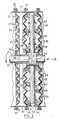
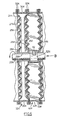
- FIGS 6 and 7 show an alternative embodiment of the invention. Elements of this embodiment corresponding to elements in the embodiment illustrated in Figures 1-4 have been given the same reference numerals followed by the letter "H".
- This embodiment has been designed to reduce freeze-up and alleviate some of the problems which may occur if freeze-up of any of the individual ice-making regions occurs. Normally when freeze-up occurs, damage to the equipment will result since the blade in the frozen region will be inhibited from rotating with the shaft.
- this embodiment is dimilar to the embodiment of Figures 1-4 except that the sleeve 52H is connected to the shaft 20H by a breakable shear pin 82.
- a pair of diametrically opposed scrapers 84 are located on the sleeve 52H. These scrapers are of generally the same shape as the blade assemblies 46H, however, their edges 88 are spaced from the heat exchange surfaces.
- the scrapers 84 In operation, if freeze-up occurs, the scrapers 84 will scrape away any excess buildup of ice on the heat exchanger surfaces 26H. If too much ice builds up and the scrapers cannot remove it, the shear pin will break and allow rotation of the shaft relative to the sleeve 52H.
- a slip arrangement comprises a first brake pad 90 keyed to the sleeve 52J by interlocking splines and a second brake pad 92 keyed to the shaft 20J by interlocking splines.
- a ring 94 is attached to the shaft adjacent to the brake pad 92 and a spring 96 is disposed between this ring 94 and the brake pad 92 to bias the second brake 92 pad into contact with the first pad 90.
- the frictional force between the brake pads will provide for common rotation of the sleeve 52J and shaft 20J.
- rotation of the sleeve 52J will be inhibited and the frictional froce between the brake pads 90, 92 will overcome to allow for relative rotation between the sleeve 52J and shaft 20J.
- the brake pads may be enclosed in a housing (not shown) if desired to avoid any interference from the ice-making environment.
- This slip arrangement can be replaced by a shear pin, a friction coupling or any device that would be apparent to one skilled in the art that would provide for common rotation of the sleeve 52H and shaft 20H under normal circumstances and provide for decoupling of the sleeve and shaft when freeze-up occurs to an extent that the sleeve is inhibited from rotating.
- heat exchangers 24 and ice-making regions 38 there can be any number of heat exchangers 24 and ice-making regions 38. There could be one inlet for the ice-making regions 38 and one outlet, with fluid communication between ice-making regions. Also, the blades 58 could be carried by rotating disks instead of arms 48.
Landscapes
- Engineering & Computer Science (AREA)
- Physics & Mathematics (AREA)
- Thermal Sciences (AREA)
- Mechanical Engineering (AREA)
- General Engineering & Computer Science (AREA)
- Heat-Exchange Devices With Radiators And Conduit Assemblies (AREA)
- Exhaust Gas After Treatment (AREA)
Claims (18)
- Eismaschine mit einem Gehäuse,
mit einer Vielzahl von Wärmeaustauschern, die in dem genannten Gehäuse angeordnet sind und die jeweils einen Einlaß und einen Auslaß aufweisen, um dadurch die Zirkulation eines Kühlmittels zu ermöglichen,
wobei jeder der genannten Wärmeaustauscher ein Paar von entgegengesetzt gerichteten Wärmeaustauschoberflächen für die Übertragung von Wärme von dem Fluid innerhalb des genannten Gehäuses zu dem Kühlmittel umfaßt,
wobei zwischen den genannten Wärmeaustauschern Eisherstellbereiche angeordnet sind, deren jeder einen Einlaß und einen Auslaß aufweist, um dadurch die Zirkulation eines Fluids zu ermöglichen,
wobei in jedem der genannten Eisherstellbereiche Blattvorrichtungen untergebracht sind, um mit den genannten Wärmeaustauschern zusammenzuarbeiten, damit die Ablagerung von Eis auf den Wärmeaustauscheroberflächen verhindert ist,
wobei die Blattvorrichtungen jeweils zumindest ein Blatt umfassen und um eine Achse drehbar sind, die generell rechtwinklig zu einer Ebene verläuft, welche die betreffenden Wärmeaustauscheroberflächen enthält,
und mit einer Antriebseinrichtung zur Drehung der Blattvorrichtungen,
dadurch gekennzeichnet,
daß zumindest eine der entgegengesetzt gerichteten Wärmeaustauscheroberflächen konzentrische Rippen aufweist, die um die genannte Achse verlaufen,
daß zumindest das genannte eine Blatt von komplementärer Form zu den genannten Wärmeaustauscherflächen ist und daß die Antriebseinrichtung die Blattvorrichtungen mit einer derartigen Geschwindigkeit dreht, daß das Intervall zwischen aufeinanderfolgenden Durchläufen der genannten Blattvorrichtungen unzureichend ist, eine Kristallisation von Eis auf den genannten Wärmeaustauscherflächen zu ermöglichen. - Eismaschine nach Anspruch 1, wobei eine Oberfläche eines der Wärmeaustauscher zu einer Oberfläche eines anderen Wärmeaustauschers der genannten Wärmeaustauscher hin gerichtet ist,
wobei jede der Blattvorrichtungen zwei Paare von Blättern aufweist, die auf einem gemeinsamen Träger getragen und in Übereinstimmung miteinander drehbar sind,
und wobei ein Blattpaar zu einem der Wärmeaustauscher und das andere Blattpaar zu dem anderen Wärmeaustauscher hin gerichtet ist. - Eismaschine nach Anspruch 2, wobei jedes der genannten Blätter um eine parallel zu der genannten Wärmeaustauscher-oberfläche verlaufende Achse in Eingriff mit der betreffenden Oberfläche bewegbar ist.
- Eismaschine nach Anspruch 3, wobei der genannte gemeinsame Träger ein Arm ist, der von einer durch das betreffende Gehäuse sich erstreckenden drehbaren Welle getragen ist.
- Eismaschine nach Anspruch 4, wobei die Blätter zu der Ebene der Wärmeaustauscheroberflächen hin geneigt sind.
- Eismaschine nach Anspruch 5, wobei die Blätter an dem genannten Arm schwenkbar angebracht sind.
- Eismaschine nach Anspruch 5, wobei jedes der genannten Blätter zu den Wärmeaustauscheroberflächen hin mittels einer Vorspannungseinrichtung vorgespannt ist.
- Eismaschine nach Anspruch 7, wobei jedes Paar von Blättern ein über die gesamte Länge des genannten Armes sich erstreckendes Blatt umfaßt.
- Eismaschine nach Anspruch 7, wobei jedes Paar von Blättern eine Vielzahl von Blattsegmenten umfaßt, wobei jedes Segment sich lediglich über einen Teil der Länge des genannten Armes erstreckt und mit dem betreffenden Arm schwenkbar verbunden ist und wobei die Segmente sich über die gesamte Länge des betreffenden Armes erstrecken.
- Eismaschine nach Anspruch 9, wobei die Blattsegmente eine Vielzahl von flachen Plattenstreifen umfassen, die so geformt sind, daß sie der Form der Wärmeaustauscheroberfläche entsprechen, und wobei jeder Streifen an einer Kante mit dem genannten Arm mittels einer Schraubenfeder derart verbunden ist, daß die betreffende Kante die Wärmeaustauscheroberfläche berührt.
- Eismaschine nach Anspruch 1, wobei das genannte Blatt eine flache Platte ist, die Kanten, welche in der Form der Form der Wärmeaustauscheroberflächen entsprechen, und von den genannten Kanten herabhängende Lippenteile aufweist, und wobei das genannte Blatt zwischen gegenüberliegenden Wärmeaustauscheroberflächen in dem genannten Eisherstellbereich unter einem Winkel verläuft.
- Eismaschine nach Anspruch 11, wobei das genannte Blatt mit einem Endbereich verminderter Breite verbunden ist, der an einer drehbaren Welle angebracht ist, die durch das genannte Gehäuse verläuft, und wobei der genannte Endbereich unter einem Winkel zu dem betreffenden Blatt verläuft und auf das betreffende Blatt eine Torsionskraft ausübt, um das betreffende Blatt zu den Wärmeaustauscheroberflächen hin vorzuspannen.
- Eismaschine nach Anspruch 2, wobei der genannte gemeinsame Träger eine an einer beweglichen Welle angebrachte Hülse umfaßt, der eine Reibungseinrichtung zugeordnet ist, um deren Drehung mit der Welle und eine Entkopplung der betreffenden Welle und der Hülse für die Ausführung einer relativen Drehung zwischen Welle und Hülse zu ermöglichen, wenn die Hülse an einer Drehung mit der betreffenden Welle gehindert ist.
- Eismaschine nach Anspruch 13, wobei die Reibungseinrichtung einen die betreffende Hülse mit der Welle verbindenden Scherbolzen umfaßt.
- Eismaschine nach Anspruch 13, wobei die Reibungseinrichtung eine Reibungskupplung umfaßt.
- Eismaschine nach Anspruch 13, wobei die Reibungseinrichtung ein Paar von Bremskissen umfaßt, deren eines an der betreffenden Hülse festgekeilt ist und deren anderes an der betreffenden Welle festgekeilt ist.
- Eismaschine nach Anspruch 2, umfassend ferner eine mit dem gemeinsamen Träger drehbare Abschabvorrichtung zum Abschaben überschüssigen Eises, das auf den Wärmeaustauscheroberflächen abgelagert ist.
- Eismaschine nach Anspruch 17, wobei die Abschabvorrichtung in der Form komplementär zu der Wärmeaustauscheroberfläche ausgebildet und in Abstand davon vorgesehen ist.
Priority Applications (1)
| Application Number | Priority Date | Filing Date | Title |
|---|---|---|---|
| AT87307193T ATE65125T1 (de) | 1986-08-19 | 1987-08-14 | Wellplattenwaermetauscher. |
Applications Claiming Priority (2)
| Application Number | Priority Date | Filing Date | Title |
|---|---|---|---|
| US06/897,806 US4669277A (en) | 1986-08-19 | 1986-08-19 | Corrugated plate heat exchanger |
| US897806 | 1986-08-19 |
Publications (3)
| Publication Number | Publication Date |
|---|---|
| EP0257936A2 EP0257936A2 (de) | 1988-03-02 |
| EP0257936A3 EP0257936A3 (en) | 1988-09-21 |
| EP0257936B1 true EP0257936B1 (de) | 1991-07-10 |
Family
ID=25408452
Family Applications (1)
| Application Number | Title | Priority Date | Filing Date |
|---|---|---|---|
| EP87307193A Expired - Lifetime EP0257936B1 (de) | 1986-08-19 | 1987-08-14 | Wellplattenwärmetauscher |
Country Status (9)
| Country | Link |
|---|---|
| US (1) | US4669277A (de) |
| EP (1) | EP0257936B1 (de) |
| JP (1) | JP2522958B2 (de) |
| AT (1) | ATE65125T1 (de) |
| AU (1) | AU601468B2 (de) |
| CA (1) | CA1315558C (de) |
| DE (2) | DE3771285D1 (de) |
| ES (1) | ES2002698B3 (de) |
| ZA (1) | ZA876121B (de) |
Families Citing this family (27)
| Publication number | Priority date | Publication date | Assignee | Title |
|---|---|---|---|---|
| US4802530A (en) * | 1986-08-19 | 1989-02-07 | Sunwell Engineering Company Ltd. | Corrugated plate heat exchanger |
| US5157939A (en) * | 1987-07-31 | 1992-10-27 | Heat And Control Pty. Ltd. | Ice making apparatus |
| CH677968A5 (en) * | 1988-03-08 | 1991-07-15 | Sulzer Ag | Heat exchanger for mfg. crystals - has plates in circular ring with eccentric drive shaft for scrapers |
| JPH01234770A (ja) * | 1988-03-15 | 1989-09-20 | Tetsuo Yotsuda | 人工雪の製造装置 |
| US5307646A (en) * | 1991-06-25 | 1994-05-03 | North Star Ice Equipment Corporation | Flake ice machine |
| FR2709817B1 (fr) * | 1993-09-08 | 1995-10-20 | Thermique Generale Vinicole | Dispositif d'échange de chaleur intégrant des moyens d'enlèvement d'une phase solide. |
| US5448894A (en) * | 1994-09-21 | 1995-09-12 | North Star Ice Equipment Corporation | Disk flake ice machine |
| US5632159A (en) * | 1996-03-29 | 1997-05-27 | North Star Ice Equipment Corporation | Cooling disk for flake ice machine |
| US6065610A (en) * | 1997-05-20 | 2000-05-23 | Savasort, Inc. | Manual sorting apparatus for paper products |
| FR2833340B1 (fr) | 2001-12-07 | 2004-07-02 | Lgl France | Dispositif d'echange de chaleur |
| RU2221202C1 (ru) * | 2002-10-30 | 2004-01-10 | Государственное образовательное учреждение Воронежская государственная технологическая академия | Кристаллизатор для непрерывного вымораживания и получения чешуйчатого льда |
| CA2471969A1 (en) | 2004-06-23 | 2005-12-23 | Lionel Gerber | Heat exchanger for use in an ice machine |
| FR2872269B1 (fr) | 2004-06-29 | 2006-10-20 | Lgl France Sa | Dispositif d'echange de chaleur pour machine de production de froid |
| CN103134253B (zh) * | 2013-03-27 | 2016-02-03 | 任俊 | 一种蓄冰槽中的刮冰装置 |
| US10947992B2 (en) * | 2015-08-17 | 2021-03-16 | Pedro Arnulfo Sarmiento | Convectors |
| JP6858267B2 (ja) | 2017-02-24 | 2021-04-14 | エクソンモービル アップストリーム リサーチ カンパニー | 二重目的lng/lin貯蔵タンクのパージ方法 |
| JP7153302B2 (ja) * | 2018-02-22 | 2022-10-14 | ブランテックインターナショナル株式会社 | フレークアイス製造装置 |
| MY204021A (en) | 2018-06-07 | 2024-08-01 | Exxonmobil Upstream Res Co | Pretreatment and pre-cooling of natural gas by high pressure compression and expansion |
| WO2020106397A1 (en) * | 2018-11-20 | 2020-05-28 | Exxonmobil Upstream Research Company | Methods and apparatus for improving multi-plate scraped heat exchangers |
| WO2020106394A1 (en) | 2018-11-20 | 2020-05-28 | Exxonmobil Upstream Research Company | Poly refrigerated integrated cycle operation using solid-tolerant heat exchangers |
| US11465093B2 (en) | 2019-08-19 | 2022-10-11 | Exxonmobil Upstream Research Company | Compliant composite heat exchangers |
| US20210063083A1 (en) | 2019-08-29 | 2021-03-04 | Exxonmobil Upstream Research Company | Liquefaction of Production Gas |
| US12050054B2 (en) | 2019-09-19 | 2024-07-30 | ExxonMobil Technology and Engineering Company | Pretreatment, pre-cooling, and condensate recovery of natural gas by high pressure compression and expansion |
| WO2021055021A1 (en) | 2019-09-19 | 2021-03-25 | Exxonmobil Upstream Research Company | Pretreatment and pre-cooling of natural gas by high pressure compression and expansion |
| US11806639B2 (en) | 2019-09-19 | 2023-11-07 | ExxonMobil Technology and Engineering Company | Pretreatment and pre-cooling of natural gas by high pressure compression and expansion |
| US11083994B2 (en) | 2019-09-20 | 2021-08-10 | Exxonmobil Upstream Research Company | Removal of acid gases from a gas stream, with O2 enrichment for acid gas capture and sequestration |
| KR20220062653A (ko) | 2019-09-24 | 2022-05-17 | 엑손모빌 업스트림 리서치 캄파니 | 선박의 이중 목적 극저온 탱크 또는 lng 및 액화 질소용 부유식 저장 유닛용 화물 스트리핑 기능 |
Family Cites Families (20)
| Publication number | Priority date | Publication date | Assignee | Title |
|---|---|---|---|---|
| DE4565C (de) * | 1900-01-01 | T. COOK, Ingenieur, in Philadelphia | Apparat zur Fabrikation von künstlichem Eis und zur Erzeugung kalter Luft | |
| US2259841A (en) * | 1941-10-21 | Refrigerant and method of provdj | ||
| GB155477A (en) * | 1919-11-06 | 1920-12-23 | William Clayton | Improvements relating to cooling apparatus for use in the manufacture of edible fats |
| US1678070A (en) * | 1922-08-15 | 1928-07-24 | Burmah Oil Co Ltd | Apparatus for cooling oil or other liquids |
| US1930570A (en) * | 1932-01-23 | 1933-10-17 | Vilter Mfg Co | Ice machine |
| US2054841A (en) * | 1935-02-02 | 1936-09-22 | Vilter Mfg Co | Machine for producing congealed substances |
| US2321262A (en) * | 1939-11-01 | 1943-06-08 | William H Taylor | Space heat transfer apparatus |
| US2280320A (en) * | 1940-05-20 | 1942-04-21 | Vilter Mfg Co | Ice machine |
| FR1009279A (fr) * | 1948-06-02 | 1952-05-27 | Dispositif de spatule pour machines à fabriquer les crèmes glacées | |
| GB668001A (en) * | 1949-04-27 | 1952-03-12 | Sabroe & Co As Thomas Ths | Method and apparatus for refrigeration by a circulating cooling medium |
| CH344744A (de) * | 1956-05-07 | 1960-02-29 | Vyzk Ustav Stroju Chladicich A | Kleineiserzeuger |
| GB842310A (en) * | 1958-08-15 | 1960-07-27 | Chemetron Corp | Scraped surface heat exchange apparatus |
| US3191398A (en) * | 1962-12-07 | 1965-06-29 | Mueller Brass Co | Apparatus for congealing liquids having a moving scraper |
| US3328972A (en) * | 1966-08-09 | 1967-07-04 | Struthers Scientific Int Corp | Concentration of extracts by freezing |
| NL7016466A (de) * | 1970-11-10 | 1972-05-15 | ||
| JPS5115257A (de) * | 1974-07-26 | 1976-02-06 | Sugyama Kogyo Kk | |
| DE2536063C3 (de) * | 1975-08-13 | 1978-05-24 | Sollich Kg Spezialmaschinenfabrik, 4902 Bad Salzuflen | Temperiermaschine für kakaobutterhaltige und ähnliche fetthaltige Massen, insbesondere Schokolademassen |
| JPS5560178A (en) * | 1978-10-27 | 1980-05-07 | Takeuchi Yutaka | Device for cooling viscous liquid |
| GB8405221D0 (en) * | 1984-02-29 | 1984-04-04 | Solmecs Corp Nv | Making ice |
| AU583051B2 (en) * | 1984-07-17 | 1989-04-20 | Sunwell Engineering Company Limited | Ice making machine (mark i & ii) |
-
1986
- 1986-08-19 US US06/897,806 patent/US4669277A/en not_active Expired - Lifetime
-
1987
- 1987-08-11 CA CA000544226A patent/CA1315558C/en not_active Expired - Fee Related
- 1987-08-14 AT AT87307193T patent/ATE65125T1/de not_active IP Right Cessation
- 1987-08-14 ES ES87307193T patent/ES2002698B3/es not_active Expired - Lifetime
- 1987-08-14 EP EP87307193A patent/EP0257936B1/de not_active Expired - Lifetime
- 1987-08-14 DE DE8787307193T patent/DE3771285D1/de not_active Expired - Fee Related
- 1987-08-14 DE DE198787307193T patent/DE257936T1/de active Pending
- 1987-08-18 ZA ZA876121A patent/ZA876121B/xx unknown
- 1987-08-18 AU AU77147/87A patent/AU601468B2/en not_active Ceased
- 1987-08-19 JP JP62206213A patent/JP2522958B2/ja not_active Expired - Fee Related
Non-Patent Citations (1)
| Title |
|---|
| "Wärmeaustausch und Wärmeaustauscher", Sauerländer AG 1973, page 745 * |
Also Published As
| Publication number | Publication date |
|---|---|
| CA1315558C (en) | 1993-04-06 |
| EP0257936A3 (en) | 1988-09-21 |
| AU601468B2 (en) | 1990-09-13 |
| ZA876121B (en) | 1988-04-27 |
| US4669277A (en) | 1987-06-02 |
| JPS63108177A (ja) | 1988-05-13 |
| DE3771285D1 (de) | 1991-08-14 |
| DE257936T1 (de) | 1988-11-03 |
| JP2522958B2 (ja) | 1996-08-07 |
| ATE65125T1 (de) | 1991-07-15 |
| AU7714787A (en) | 1988-02-25 |
| ES2002698A4 (es) | 1988-10-01 |
| EP0257936A2 (de) | 1988-03-02 |
| ES2002698B3 (es) | 1992-03-16 |
Similar Documents
| Publication | Publication Date | Title |
|---|---|---|
| EP0257936B1 (de) | Wellplattenwärmetauscher | |
| KR100442188B1 (ko) | 제빙기및그제빙기용열교환기 | |
| US4802530A (en) | Corrugated plate heat exchanger | |
| CA2471969A1 (en) | Heat exchanger for use in an ice machine | |
| US2321262A (en) | Space heat transfer apparatus | |
| CA2041475A1 (en) | Modular cutterbar for a rotary mower | |
| CA1276475C (en) | Ice making machine (mark i & mark ii) | |
| US4640345A (en) | Rotating heat exchanger | |
| KR100396148B1 (ko) | 튜우브와 휩 롯드 열교환기 | |
| JPS60215911A (ja) | 水上に浮遊する油の回収装置 | |
| DE69307655D1 (de) | Schabersystem für einen Dünnschicht-Wärmeaustauscher | |
| US5597036A (en) | Balanced drive with radially slotted countercrank for orbital tube whip rod heat exchanger | |
| CN215275798U (zh) | 一种食品生产用双效蒸发结晶装置 | |
| US5676236A (en) | Vane orienter with wipers | |
| JPS6373041A (ja) | 熱保存システム | |
| CA1319096C (en) | Precrystallizer | |
| CN216728663U (zh) | 一种刮冰板及干冰旋切机构 | |
| US4700551A (en) | Slice-ice producing machine | |
| KR930008005B1 (ko) | "제빙기(마크 ⅰ과 ⅱ)" | |
| JPS6219326B2 (de) | ||
| EP1022053B1 (de) | Mischer | |
| KR100341013B1 (ko) | 튜우브와휩롯드열교환기용장치와냉동또는냉각방법 | |
| CN120538348B (zh) | 一种便于维护的管壳式换热器 | |
| JPH0536715B2 (de) | ||
| SU1209941A1 (ru) | Устройство дл нагрева воздуха низкопотенциальным теплоносителем |
Legal Events
| Date | Code | Title | Description |
|---|---|---|---|
| PUAI | Public reference made under article 153(3) epc to a published international application that has entered the european phase |
Free format text: ORIGINAL CODE: 0009012 |
|
| AK | Designated contracting states |
Kind code of ref document: A2 Designated state(s): AT DE ES FR GB IT NL SE |
|
| ITCL | It: translation for ep claims filed |
Representative=s name: INTERPATENT ST.TECN. BREVETTUALE |
|
| PUAL | Search report despatched |
Free format text: ORIGINAL CODE: 0009013 |
|
| EL | Fr: translation of claims filed | ||
| TCNL | Nl: translation of patent claims filed | ||
| AK | Designated contracting states |
Kind code of ref document: A3 Designated state(s): AT DE ES FR GB IT NL SE |
|
| DET | De: translation of patent claims | ||
| 17P | Request for examination filed |
Effective date: 19890320 |
|
| 17Q | First examination report despatched |
Effective date: 19890726 |
|
| GRAA | (expected) grant |
Free format text: ORIGINAL CODE: 0009210 |
|
| AK | Designated contracting states |
Kind code of ref document: B1 Designated state(s): AT DE ES FR GB IT NL SE |
|
| REF | Corresponds to: |
Ref document number: 65125 Country of ref document: AT Date of ref document: 19910715 Kind code of ref document: T |
|
| REF | Corresponds to: |
Ref document number: 3771285 Country of ref document: DE Date of ref document: 19910814 |
|
| ITF | It: translation for a ep patent filed | ||
| ET | Fr: translation filed | ||
| REG | Reference to a national code |
Ref country code: ES Ref legal event code: FG2A Ref document number: 2002698 Country of ref document: ES Kind code of ref document: B3 |
|
| PLBE | No opposition filed within time limit |
Free format text: ORIGINAL CODE: 0009261 |
|
| STAA | Information on the status of an ep patent application or granted ep patent |
Free format text: STATUS: NO OPPOSITION FILED WITHIN TIME LIMIT |
|
| 26N | No opposition filed | ||
| PGFP | Annual fee paid to national office [announced via postgrant information from national office to epo] |
Ref country code: AT Payment date: 19930830 Year of fee payment: 7 |
|
| PG25 | Lapsed in a contracting state [announced via postgrant information from national office to epo] |
Ref country code: AT Effective date: 19940814 |
|
| EAL | Se: european patent in force in sweden |
Ref document number: 87307193.0 |
|
| PGFP | Annual fee paid to national office [announced via postgrant information from national office to epo] |
Ref country code: SE Payment date: 20000824 Year of fee payment: 14 |
|
| PGFP | Annual fee paid to national office [announced via postgrant information from national office to epo] |
Ref country code: GB Payment date: 20000830 Year of fee payment: 14 |
|
| PGFP | Annual fee paid to national office [announced via postgrant information from national office to epo] |
Ref country code: NL Payment date: 20000831 Year of fee payment: 14 |
|
| PGFP | Annual fee paid to national office [announced via postgrant information from national office to epo] |
Ref country code: DE Payment date: 20000904 Year of fee payment: 14 |
|
| PGFP | Annual fee paid to national office [announced via postgrant information from national office to epo] |
Ref country code: ES Payment date: 20000905 Year of fee payment: 14 |
|
| PGFP | Annual fee paid to national office [announced via postgrant information from national office to epo] |
Ref country code: FR Payment date: 20000912 Year of fee payment: 14 |
|
| PG25 | Lapsed in a contracting state [announced via postgrant information from national office to epo] |
Ref country code: GB Free format text: LAPSE BECAUSE OF NON-PAYMENT OF DUE FEES Effective date: 20010814 |
|
| PG25 | Lapsed in a contracting state [announced via postgrant information from national office to epo] |
Ref country code: SE Free format text: LAPSE BECAUSE OF NON-PAYMENT OF DUE FEES Effective date: 20010815 Ref country code: ES Free format text: LAPSE BECAUSE OF NON-PAYMENT OF DUE FEES Effective date: 20010815 |
|
| PG25 | Lapsed in a contracting state [announced via postgrant information from national office to epo] |
Ref country code: NL Free format text: LAPSE BECAUSE OF NON-PAYMENT OF DUE FEES Effective date: 20020301 |
|
| EUG | Se: european patent has lapsed |
Ref document number: 87307193.0 |
|
| GBPC | Gb: european patent ceased through non-payment of renewal fee |
Effective date: 20010814 |
|
| PG25 | Lapsed in a contracting state [announced via postgrant information from national office to epo] |
Ref country code: FR Free format text: LAPSE BECAUSE OF NON-PAYMENT OF DUE FEES Effective date: 20020430 |
|
| NLV4 | Nl: lapsed or anulled due to non-payment of the annual fee |
Effective date: 20020301 |
|
| PG25 | Lapsed in a contracting state [announced via postgrant information from national office to epo] |
Ref country code: DE Free format text: LAPSE BECAUSE OF NON-PAYMENT OF DUE FEES Effective date: 20020501 |
|
| REG | Reference to a national code |
Ref country code: FR Ref legal event code: ST |
|
| REG | Reference to a national code |
Ref country code: ES Ref legal event code: FD2A Effective date: 20020911 |
|
| PG25 | Lapsed in a contracting state [announced via postgrant information from national office to epo] |
Ref country code: IT Free format text: LAPSE BECAUSE OF NON-PAYMENT OF DUE FEES;WARNING: LAPSES OF ITALIAN PATENTS WITH EFFECTIVE DATE BEFORE 2007 MAY HAVE OCCURRED AT ANY TIME BEFORE 2007. THE CORRECT EFFECTIVE DATE MAY BE DIFFERENT FROM THE ONE RECORDED. Effective date: 20050814 |