EP0257965A2 - Fabrication de maquettes - Google Patents
Fabrication de maquettes Download PDFInfo
- Publication number
- EP0257965A2 EP0257965A2 EP19870307293 EP87307293A EP0257965A2 EP 0257965 A2 EP0257965 A2 EP 0257965A2 EP 19870307293 EP19870307293 EP 19870307293 EP 87307293 A EP87307293 A EP 87307293A EP 0257965 A2 EP0257965 A2 EP 0257965A2
- Authority
- EP
- European Patent Office
- Prior art keywords
- main axis
- points
- frame structure
- image
- shaping
- Prior art date
- Legal status (The legal status is an assumption and is not a legal conclusion. Google has not performed a legal analysis and makes no representation as to the accuracy of the status listed.)
- Withdrawn
Links
Images




Classifications
-
- B—PERFORMING OPERATIONS; TRANSPORTING
- B44—DECORATIVE ARTS
- B44B—MACHINES, APPARATUS OR TOOLS FOR ARTISTIC WORK, e.g. FOR SCULPTURING, GUILLOCHING, CARVING, BRANDING, INLAYING
- B44B1/00—Artists' machines or apparatus equipped with tools or work holders moving, or able to be controlled, three-dimensionally for making single sculptures or models
- B44B1/02—Artists' machines or apparatus equipped with tools or work holders moving, or able to be controlled, three-dimensionally for making single sculptures or models wherein three-dimensional [3D] copies are made
-
- B—PERFORMING OPERATIONS; TRANSPORTING
- B23—MACHINE TOOLS; METAL-WORKING NOT OTHERWISE PROVIDED FOR
- B23Q—DETAILS, COMPONENTS, OR ACCESSORIES FOR MACHINE TOOLS, e.g. ARRANGEMENTS FOR COPYING OR CONTROLLING; MACHINE TOOLS IN GENERAL CHARACTERISED BY THE CONSTRUCTION OF PARTICULAR DETAILS OR COMPONENTS; COMBINATIONS OR ASSOCIATIONS OF METAL-WORKING MACHINES, NOT DIRECTED TO A PARTICULAR RESULT
- B23Q1/00—Members which are comprised in the general build-up of a form of machine, particularly relatively large fixed members
- B23Q1/01—Frames, beds, pillars or like members; Arrangement of ways
- B23Q1/015—Frames, beds, pillars
-
- B—PERFORMING OPERATIONS; TRANSPORTING
- B23—MACHINE TOOLS; METAL-WORKING NOT OTHERWISE PROVIDED FOR
- B23Q—DETAILS, COMPONENTS, OR ACCESSORIES FOR MACHINE TOOLS, e.g. ARRANGEMENTS FOR COPYING OR CONTROLLING; MACHINE TOOLS IN GENERAL CHARACTERISED BY THE CONSTRUCTION OF PARTICULAR DETAILS OR COMPONENTS; COMBINATIONS OR ASSOCIATIONS OF METAL-WORKING MACHINES, NOT DIRECTED TO A PARTICULAR RESULT
- B23Q1/00—Members which are comprised in the general build-up of a form of machine, particularly relatively large fixed members
- B23Q1/25—Movable or adjustable work or tool supports
- B23Q1/44—Movable or adjustable work or tool supports using particular mechanisms
- B23Q1/48—Movable or adjustable work or tool supports using particular mechanisms with sliding pairs and rotating pairs
-
- G—PHYSICS
- G05—CONTROLLING; REGULATING
- G05B—CONTROL OR REGULATING SYSTEMS IN GENERAL; FUNCTIONAL ELEMENTS OF SUCH SYSTEMS; MONITORING OR TESTING ARRANGEMENTS FOR SUCH SYSTEMS OR ELEMENTS
- G05B19/00—Program-control systems
- G05B19/02—Program-control systems electric
- G05B19/42—Recording and playback systems, i.e. in which the program is recorded from a cycle of operations, e.g. the cycle of operations being manually controlled, after which this record is played back on the same machine
- G05B19/4202—Recording and playback systems, i.e. in which the program is recorded from a cycle of operations, e.g. the cycle of operations being manually controlled, after which this record is played back on the same machine preparation of the program medium using a drawing, a model
- G05B19/4207—Recording and playback systems, i.e. in which the program is recorded from a cycle of operations, e.g. the cycle of operations being manually controlled, after which this record is played back on the same machine preparation of the program medium using a drawing, a model in which a model is traced or scanned and corresponding data recorded
-
- G—PHYSICS
- G05—CONTROLLING; REGULATING
- G05B—CONTROL OR REGULATING SYSTEMS IN GENERAL; FUNCTIONAL ELEMENTS OF SUCH SYSTEMS; MONITORING OR TESTING ARRANGEMENTS FOR SUCH SYSTEMS OR ELEMENTS
- G05B2219/00—Program-control systems
- G05B2219/30—Nc systems
- G05B2219/37—Measurements
- G05B2219/37425—Distance, range
-
- G—PHYSICS
- G05—CONTROLLING; REGULATING
- G05B—CONTROL OR REGULATING SYSTEMS IN GENERAL; FUNCTIONAL ELEMENTS OF SUCH SYSTEMS; MONITORING OR TESTING ARRANGEMENTS FOR SUCH SYSTEMS OR ELEMENTS
- G05B2219/00—Program-control systems
- G05B2219/30—Nc systems
- G05B2219/37—Measurements
- G05B2219/37554—Two camera, or tiltable camera to detect different surfaces of the object
-
- G—PHYSICS
- G05—CONTROLLING; REGULATING
- G05B—CONTROL OR REGULATING SYSTEMS IN GENERAL; FUNCTIONAL ELEMENTS OF SUCH SYSTEMS; MONITORING OR TESTING ARRANGEMENTS FOR SUCH SYSTEMS OR ELEMENTS
- G05B2219/00—Program-control systems
- G05B2219/30—Nc systems
- G05B2219/49—Nc machine tool, till multiple
- G05B2219/49007—Making, forming 3-D object, model, surface
Definitions
- This invention relates to a model making method.
- the present invention provides a model making method comprising the steps of providing a machine to determine the x, y, z co-ordinates of points on the surface of an object, processing the information determined by said machine into instruction data, and providing a machine operable in response to said instruction data to embody in a 3-dimensional medium a model or mould of the object.
- the invention also provides shaping apparatus comprising clamping means for mounting a block of material to be shaped, means concentrically mounting two frame structures for independent rotational movement about a main axis and around a block of material mounted in said clamping means, at least two cutting heads for shaping the block of material, means mounting at least one of the cutting heads on each frame structure to enable movement of the cutting heads relative to their respective frame structure in directions parallel to and radially with respect to said main axis and about a rotational axis prependicular to said main axis, and means to control operation of the cutting heads and movement of the frame structures and the cutting heads.
- the invention further provides shaping apparatus comprising a frame structure, at least one cutting head for shaping material, means mounting the cutting head on the frame structure to enable movement of the cutting head relative to the frame structure in a direction parallel to a main axis, perpendicular to said main axis and about a rotational axis perpendicular to said main axis, means being provided for attaching the frame structure to a surface to be shaped, eg a wall, with said main axis normal to the surface, and means to control operation and movement of the cutting head.
- the invention further provides a data processing system using at least two cameras to produce two TV images of an object to be modelled, and means to calculate the x, y, z co-ordinates for each point on the surface of the object by matching the projection on the two TV images of each said point according to the following steps: selecting on a first TV image a pixel corresponding to a point on the surface of the object and producing an imaginery chord line from the pixel passing through the central axis of the respective camera lens, producing two imaginery planes on either side of the object and determining the x, y co-ordinates of the points of intersection of the imaginery chord line with said imaginery planes, relating said points of intersection to the second TV image and representing said points of intersection by two respective pixels on the second TV image, searching in between said two respective pixels on the second TV image to find a pixel with the same grey level as the selected pixel on the first TV image and comparing characteristics of neighbouring pixels to find corresponding pixels on both TV images, enabling calculation of the x, y, z co
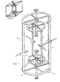
- the apparatus comprises a chassis 1 with protection grids and doors (not shown).
- the chassis 1 houses and supports the moving parts of the apparatus through support shafts 2 , support arms 3 and support rollers 4 .
- the block of material to be modelled is fixed by adjustable grips 5 and is shaped by cutting heads 6 which are held and powered by rotating tool grip 7 .
- the cutting heads 6 can move : transversely by sliders 9 , up and down by vertical guides 10 which are fixed to the upper and lower rings to make rotating frames 11 and 12 . These frames can rotate independently around shaft 2 by the use of bearings 13 and can give the cutting heads a circular motion.
- Control boxes 8 control the motion and angle F of sliders 9 , and the motion on vertical guides 10 .
- Control boxes 14 control the rotation of rotating frames 11 and 12 . The coordination of the tips of the cutting heads is thus controlled by the computer whose data configures the shape of the object.
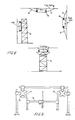
- the apparatus comprises two multi-slider, extendible guide beams 20 on which supports 21 can be secured and sliding control boxes 22 can travel.
- Adjustable bars 23 and columns 24 fix the position of the guide beams.
- Sliding control boxes 22 support and move the vertical guide bars 29 and guide lintels 30 .
- Several sliding sets 22 could be incorporated simultaneously and guides beams 20 could be extended by similar pieces from both sides.
- the material is carved by suitable bits 28 which are held and powered through grip 27 , sliding arms 26 and control boxes 25 which are guided by bars 29 or lintels 30 .
- Vertical guides 29 could also be used for guiding and holding lintels capable of vertical movement.
- Control boxes 25 and 22 dictate the coordination of the tip of the shaping bits, under the control of the computer.
- the whole machine is fastened to the surface, eg wall, floor or ceiling using, eg cables 31 and suitable supports, or alternatively on a gantry or supporting frame-work 32 when the place being carved is not too high.
- any non-contact meansurement system can be utilized in this method.
- These systems basically include a vision part through which the scene is presented to the system and an extraction part by which the three-dimensional information is obtained.
- various optical manipulation and light effects could be used depending on the size of the object:
- the CCD or video cameras give the frame stores the data configured by the image of the scene.
- the data is transferred through proper interfaces.
- the images are analysed, ie, each point on the image of the object is distinguished by its x, y coordinates and a grey level representing the intensity of light reflected by that point.
- the z dimension of the points can be calculated in the following ways:
- the computer is programmed for calculation of the x,y,z coordinates of the points on the object and the subsequent data processing through a software program.
- the software is capable of storing and re-forming the co-ordinate data for giving different actions such as representation of the object on a TV screen for inspection and possible retouches, dissecting and super-imposing the shapes of the objects.
- the software is also used for providing NC machines with the instruction data on tool path, carving stages and scaling of the model, etc.
- NC machines numerically controlled machines
- Different sizes and materials of the finished models deserve specific NC machines.
- Cylindrical coordination can be used for production of busts and statues, and special gantry machines for ornamental and large scale models.
- ESP method automates the electronic stereo photogrammetry (ESP) method.
- ESP method is an existing method for determination of the x, y, z co-ordinates of the points on the surface of an object based on close range photogrammetry.
- Two stereoscopic TV images, instead of photographs are used by means of appropriate hardware and ESP software.
- ESP method is basically non-automatic, ie, for locating the two projections of each point on the two TV screens human observation and judgement is used, which is one of the shortcomings of ESP method.
- Different approaches have been examined for automation of ESP method, which are generally not feasible for practical uses. In one of these approaches, a pixel "P1" on one of TV screens is selected and the grey levels of the eight adjacent pixels are identified.
- the present software comprises the following segments:
- the system comprises a vision compartment consisting of three video or CCD cameras with spot laser beam emitters, lighting set with time dimmer switch all installed on a holder frame work, interfaces and triple image analyser hardware and required software.
- the vision compartment provides the computer with triple scenes from each side of the object, with reference points facilitated by laser beams on the objects.
- the apparatus is secured to column shaft 1 by means of sliding grip 2 , holding horizontal shaft 3 .
- Triple grip 4 gives arms 5 the possibility of independent positioning around and along shaft 3 .
- Grips 6 via adjustable joints 7 connect guide bars 8 to arms 5 .
- Sliding camera seats 9 provide the cameras with facility of rotation and horizontal movement around and along guide bars 8 .
- the three cameras could have any desired position relative to each other.
- the lighting set 10 is installed which lights the object with variable intensity facilitated by a time dimmer. The scene is detected by the three cameras from a dark state to a maximum intensity.
- a laser beam generator is incorporated with each camera to emit a beam of safe light from the axis of the lens of the camera to the object.
- the data thus collected transferred from the cameras through the appropriate interfaces to storage/recording media of the triple image analyser.
- the triple image analyser is basically an ESP system with appropriate adjustments for three incoming images.
- the software is the chord search software described above.
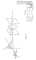
- the chord QS could be located on two screens, Figure I, and the search time will be reduced, as searching for R1 can be started from one side of the chord say Q1, and that of image 2 (R2) from the other side, say S2, and the first match will be done in a time less than half of that of two camera systems.
- the computation results can also be double checked for more accuracy.
- the bright laser points A,B,C on the object could be used to obtain the absolute dimensions knowing the configuration of the cameras.
- the object can belrotated or the system could be travelled around the object for a complete survey.
- the system is also capable of cylindrical and polar coordination data processing by adjusting the relative position of the cameras and giving the software the required commands.
Landscapes
- Engineering & Computer Science (AREA)
- Mechanical Engineering (AREA)
- Physics & Mathematics (AREA)
- General Physics & Mathematics (AREA)
- Automation & Control Theory (AREA)
- Length Measuring Devices By Optical Means (AREA)
- Numerical Control (AREA)
- Machine Tool Copy Controls (AREA)
- Image Processing (AREA)
Applications Claiming Priority (2)
| Application Number | Priority Date | Filing Date | Title |
|---|---|---|---|
| GB8620040 | 1986-08-18 | ||
| GB868620040A GB8620040D0 (en) | 1986-08-18 | 1986-08-18 | Model making |
Publications (2)
| Publication Number | Publication Date |
|---|---|
| EP0257965A2 true EP0257965A2 (fr) | 1988-03-02 |
| EP0257965A3 EP0257965A3 (fr) | 1990-05-02 |
Family
ID=10602857
Family Applications (1)
| Application Number | Title | Priority Date | Filing Date |
|---|---|---|---|
| EP87307293A Withdrawn EP0257965A3 (fr) | 1986-08-18 | 1987-08-18 | Fabrication de maquettes |
Country Status (2)
| Country | Link |
|---|---|
| EP (1) | EP0257965A3 (fr) |
| GB (2) | GB8620040D0 (fr) |
Cited By (6)
| Publication number | Priority date | Publication date | Assignee | Title |
|---|---|---|---|---|
| WO1996028927A1 (fr) * | 1995-03-13 | 1996-09-19 | David Russell Herbert | Procede et systeme de translation entre une image et un relief tridimensionnel |
| WO1998046310A3 (fr) * | 1997-04-15 | 1999-01-21 | Jury Vasilievich Khalezov | Procede et appareil de protection des organes respiratoires d'une personne |
| WO2001068314A3 (fr) * | 2000-03-15 | 2002-08-08 | Hubert Haller | Centre d'usinage |
| WO2010114350A3 (fr) * | 2009-04-01 | 2010-11-18 | Rfid Mexico S.A. De C.V. | Système pour concevoir et produire des motifs personnalisés pour des moules de stockage ou de transport |
| WO2021001247A1 (fr) * | 2019-07-01 | 2021-01-07 | Uniwersytet Jagiellonski | Gabarit d'aide à l'étirage spatial |
| CN114453978A (zh) * | 2022-01-18 | 2022-05-10 | 东莞市银泽实业有限公司 | 一种钻头抖动分析及外径测量装置 |
Families Citing this family (8)
| Publication number | Priority date | Publication date | Assignee | Title |
|---|---|---|---|---|
| US5088047A (en) * | 1989-10-16 | 1992-02-11 | Bynum David K | Automated manufacturing system using thin sections |
| US5452219A (en) * | 1990-06-11 | 1995-09-19 | Dentsply Research & Development Corp. | Method of making a tooth mold |
| US5691905A (en) * | 1990-06-11 | 1997-11-25 | Dentsply Research & Development Corp. | Prosthetic teeth and mold making and polishing therefor |
| US5127037A (en) * | 1990-08-15 | 1992-06-30 | Bynum David K | Apparatus for forming a three-dimensional reproduction of an object from laminations |
| GB2270435A (en) * | 1992-09-05 | 1994-03-09 | Ibm | Stereogrammetry |
| US5543103A (en) * | 1994-05-31 | 1996-08-06 | Hogan; S. David | Process of surface shaping |
| US5718585A (en) * | 1995-09-15 | 1998-02-17 | Dentsply Research & Development Corp. | Prosthetic teeth and mold making therefor |
| CN102689558B (zh) * | 2012-06-19 | 2014-04-02 | 常州市新罗特数控机械有限公司 | 茶盘雕刻机 |
Family Cites Families (12)
| Publication number | Priority date | Publication date | Assignee | Title |
|---|---|---|---|---|
| DE73887C (de) * | A. E. KNOX und G. STEWART in Glasgow | Vielfach-Graviermaschine | ||
| US2862421A (en) * | 1956-07-11 | 1958-12-02 | Cincinnati Milling Machine Co | Spar milling machine |
| DE1463254B2 (de) * | 1963-01-14 | 1972-05-04 | Giddings & Lewis, Inc., Fond du Lac, Wis. (V.StA.) | Servosteuereinrichtung zum steuern der bewegung eines maschinenelementes laengs einer achse |
| US3609322A (en) * | 1969-04-17 | 1971-09-28 | Cincinnati Milacron Inc | Digital tracer control |
| US3854379A (en) * | 1972-08-21 | 1974-12-17 | Uzina De Autocamioane Brasov | Toroidal surface processing machine |
| JPS50101988A (fr) * | 1974-01-12 | 1975-08-12 | ||
| AT367552B (de) * | 1979-05-11 | 1982-07-12 | Chlestil Gustav Dkfm Ing | Verfahren zur fotografischen herstellung von datentraegern fuer die reproduktion dreidimensionaler objekte, vorrichtung zur durch- fuehrung des verfahrens und reproduktionseinrichtung |
| DE2936847A1 (de) * | 1979-09-12 | 1981-03-19 | Paul Dr. 6054 Rodgau Heitlinger | Verfahren zur herstellung von zahnersatz und vorrichtung zur durchfuehrung des verfahrens |
| DE3101226A1 (de) * | 1981-01-16 | 1982-09-02 | Josef M. 8934 Großaitingen Röhrich | Verfahren und vorrichtung zur herstellung von bildhauererzeugnissen |
| US4436684A (en) * | 1982-06-03 | 1984-03-13 | Contour Med Partners, Ltd. | Method of forming implantable prostheses for reconstructive surgery |
| NZ207890A (en) * | 1983-04-26 | 1986-02-21 | Doherty R G | Kerb engraving machine attached to kerb by suction cups |
| EP0163076B1 (fr) * | 1984-04-17 | 1991-11-13 | Kawasaki Jukogyo Kabushiki Kaisha | Dispositif pour réaliser une copie tridimensionelle d'un objet |
-
1986
- 1986-08-18 GB GB868620040A patent/GB8620040D0/en active Pending
-
1987
- 1987-08-17 GB GB8719447A patent/GB2197502B/en not_active Expired - Lifetime
- 1987-08-18 EP EP87307293A patent/EP0257965A3/fr not_active Withdrawn
Cited By (8)
| Publication number | Priority date | Publication date | Assignee | Title |
|---|---|---|---|---|
| WO1996028927A1 (fr) * | 1995-03-13 | 1996-09-19 | David Russell Herbert | Procede et systeme de translation entre une image et un relief tridimensionnel |
| WO1998046310A3 (fr) * | 1997-04-15 | 1999-01-21 | Jury Vasilievich Khalezov | Procede et appareil de protection des organes respiratoires d'une personne |
| WO2001068314A3 (fr) * | 2000-03-15 | 2002-08-08 | Hubert Haller | Centre d'usinage |
| JP2003526525A (ja) * | 2000-03-15 | 2003-09-09 | ハラー,フーベルト | マシニングセンター |
| US6752573B2 (en) | 2000-03-15 | 2004-06-22 | Hubert Haller | Machining center |
| WO2010114350A3 (fr) * | 2009-04-01 | 2010-11-18 | Rfid Mexico S.A. De C.V. | Système pour concevoir et produire des motifs personnalisés pour des moules de stockage ou de transport |
| WO2021001247A1 (fr) * | 2019-07-01 | 2021-01-07 | Uniwersytet Jagiellonski | Gabarit d'aide à l'étirage spatial |
| CN114453978A (zh) * | 2022-01-18 | 2022-05-10 | 东莞市银泽实业有限公司 | 一种钻头抖动分析及外径测量装置 |
Also Published As
| Publication number | Publication date |
|---|---|
| GB2197502A (en) | 1988-05-18 |
| GB8620040D0 (en) | 1986-10-01 |
| GB8719447D0 (en) | 1987-09-23 |
| EP0257965A3 (fr) | 1990-05-02 |
| GB2197502B (en) | 1991-04-10 |
Similar Documents
| Publication | Publication Date | Title |
|---|---|---|
| CN111897332B (zh) | 一种语义智能变电站机器人仿人巡视作业方法及系统 | |
| US5243665A (en) | Component surface distortion evaluation apparatus and method | |
| DE69628956T2 (de) | Abtastvorrichtung und -verfahren | |
| CN207487590U (zh) | 视觉测量试验平台 | |
| Fontana et al. | Three-dimensional modelling of statues: the Minerva of Arezzo | |
| CN114413788A (zh) | 基于双目视觉和反向模型重构的零件表面图案检测方法 | |
| EP1424656B1 (fr) | Procédé et appareil pour la génération des données de model tridimensionnelles pour machine-outil | |
| US10579890B2 (en) | Automatic alignment of a 3D model to a test object | |
| GB2197502A (en) | Model making | |
| EP0391498A1 (fr) | Système de surveillance assisté par ordinateur pour obtenir à trois dimensions une information topographique numérique | |
| US20130278725A1 (en) | Integrated Structured Light 3D Scanner | |
| US11378693B2 (en) | Floor surveying system | |
| CA2179233C (fr) | Systeme combinant un galvanometre et une camera | |
| US4933864A (en) | Mobile robot navigation employing ceiling light fixtures | |
| US5414647A (en) | Non-contact method and system for building CAD models by integrating high density data scans | |
| DE4026942A1 (de) | Verfahren zur beruehrungslosen vermessung von objektoberflaechen | |
| WO2023087125A1 (fr) | Système intégré de balayage et de fraisage pouvant être monté, et son procédé d'utilisation | |
| CN86105861A (zh) | 从至少一组立体照片对中提取三维定量信息的设备 | |
| CN217384166U (zh) | 一种用于工业的扫描检测装置 | |
| Tucci et al. | Application of high resolution scanning systems for virtual moulds and replicas of sculptural works | |
| Cote et al. | Augmented reality graphic interface for upstream dam inspection | |
| Jagieła–Zając et al. | Measurement of the pick holders position on the side surface of the cutting head of a mining machine with the use of stereoscopic vision | |
| Rabensteiner et al. | Automation and digitalisation of the geological documentation in tunnelling | |
| Nakamura et al. | Developing a support system for loading planning | |
| JPH0981788A (ja) | 環境モデル入力装置 |
Legal Events
| Date | Code | Title | Description |
|---|---|---|---|
| PUAI | Public reference made under article 153(3) epc to a published international application that has entered the european phase |
Free format text: ORIGINAL CODE: 0009012 |
|
| AK | Designated contracting states |
Kind code of ref document: A2 Designated state(s): AT BE CH DE ES FR GR IT LI LU NL SE |
|
| PUAL | Search report despatched |
Free format text: ORIGINAL CODE: 0009013 |
|
| AK | Designated contracting states |
Kind code of ref document: A3 Designated state(s): AT BE CH DE ES FR GR IT LI LU NL SE |
|
| 17P | Request for examination filed |
Effective date: 19901102 |
|
| 17Q | First examination report despatched |
Effective date: 19920410 |
|
| RAP3 | Party data changed (applicant data changed or rights of an application transferred) |
Owner name: SAMANGOOIE, FAZLOLLAH |
|
| STAA | Information on the status of an ep patent application or granted ep patent |
Free format text: STATUS: THE APPLICATION IS DEEMED TO BE WITHDRAWN |
|
| 18D | Application deemed to be withdrawn |
Effective date: 19930301 |