EP0258028A2 - Elektrische Kabel - Google Patents
Elektrische Kabel Download PDFInfo
- Publication number
- EP0258028A2 EP0258028A2 EP87307465A EP87307465A EP0258028A2 EP 0258028 A2 EP0258028 A2 EP 0258028A2 EP 87307465 A EP87307465 A EP 87307465A EP 87307465 A EP87307465 A EP 87307465A EP 0258028 A2 EP0258028 A2 EP 0258028A2
- Authority
- EP
- European Patent Office
- Prior art keywords
- conductor
- cable
- electrical cable
- magnetic material
- magnetic
- Prior art date
- Legal status (The legal status is an assumption and is not a legal conclusion. Google has not performed a legal analysis and makes no representation as to the accuracy of the status listed.)
- Withdrawn
Links
- 239000004020 conductor Substances 0.000 claims abstract description 46
- 239000000696 magnetic material Substances 0.000 claims abstract description 29
- 229910000859 α-Fe Inorganic materials 0.000 claims abstract description 20
- 239000000463 material Substances 0.000 claims description 14
- QELJHCBNGDEXLD-UHFFFAOYSA-N nickel zinc Chemical compound [Ni].[Zn] QELJHCBNGDEXLD-UHFFFAOYSA-N 0.000 claims description 5
- 239000002245 particle Substances 0.000 claims description 4
- WJZHMLNIAZSFDO-UHFFFAOYSA-N manganese zinc Chemical compound [Mn].[Zn] WJZHMLNIAZSFDO-UHFFFAOYSA-N 0.000 claims description 3
- 238000009413 insulation Methods 0.000 abstract description 22
- 230000008054 signal transmission Effects 0.000 abstract description 3
- 239000011810 insulating material Substances 0.000 abstract 1
- 230000005540 biological transmission Effects 0.000 description 15
- 239000012212 insulator Substances 0.000 description 8
- 230000008901 benefit Effects 0.000 description 6
- 230000000694 effects Effects 0.000 description 6
- 230000001939 inductive effect Effects 0.000 description 6
- 230000035699 permeability Effects 0.000 description 5
- 239000000126 substance Substances 0.000 description 4
- 238000009826 distribution Methods 0.000 description 3
- 230000008859 change Effects 0.000 description 2
- 239000002131 composite material Substances 0.000 description 2
- 230000003247 decreasing effect Effects 0.000 description 2
- 230000006872 improvement Effects 0.000 description 2
- 239000006249 magnetic particle Substances 0.000 description 2
- 238000004519 manufacturing process Methods 0.000 description 2
- 239000000758 substrate Substances 0.000 description 2
- 208000032365 Electromagnetic interference Diseases 0.000 description 1
- 229910001289 Manganese-zinc ferrite Inorganic materials 0.000 description 1
- JIYIUPFAJUGHNL-UHFFFAOYSA-N [O--].[O--].[O--].[O--].[O--].[O--].[O--].[O--].[O--].[O--].[O--].[O--].[O--].[O--].[O--].[O--].[O--].[O--].[O--].[O--].[Mn++].[Mn++].[Mn++].[Fe+3].[Fe+3].[Fe+3].[Fe+3].[Fe+3].[Fe+3].[Fe+3].[Fe+3].[Fe+3].[Fe+3].[Zn++].[Zn++] Chemical compound [O--].[O--].[O--].[O--].[O--].[O--].[O--].[O--].[O--].[O--].[O--].[O--].[O--].[O--].[O--].[O--].[O--].[O--].[O--].[O--].[Mn++].[Mn++].[Mn++].[Fe+3].[Fe+3].[Fe+3].[Fe+3].[Fe+3].[Fe+3].[Fe+3].[Fe+3].[Fe+3].[Fe+3].[Zn++].[Zn++] JIYIUPFAJUGHNL-UHFFFAOYSA-N 0.000 description 1
- 239000002253 acid Substances 0.000 description 1
- 150000007513 acids Chemical class 0.000 description 1
- 239000002826 coolant Substances 0.000 description 1
- 238000001816 cooling Methods 0.000 description 1
- 230000002939 deleterious effect Effects 0.000 description 1
- 239000006185 dispersion Substances 0.000 description 1
- 239000002019 doping agent Substances 0.000 description 1
- 230000002500 effect on skin Effects 0.000 description 1
- 230000005672 electromagnetic field Effects 0.000 description 1
- 230000008030 elimination Effects 0.000 description 1
- 230000002708 enhancing effect Effects 0.000 description 1
- 239000010419 fine particle Substances 0.000 description 1
- 239000000446 fuel Substances 0.000 description 1
- 238000010438 heat treatment Methods 0.000 description 1
- 239000012774 insulation material Substances 0.000 description 1
- 238000012886 linear function Methods 0.000 description 1
- 239000007788 liquid Substances 0.000 description 1
- 229910052751 metal Inorganic materials 0.000 description 1
- 239000002184 metal Substances 0.000 description 1
- 229910001092 metal group alloy Inorganic materials 0.000 description 1
- 150000002739 metals Chemical class 0.000 description 1
- 238000000034 method Methods 0.000 description 1
- 239000000203 mixture Substances 0.000 description 1
- 238000010248 power generation Methods 0.000 description 1
- 230000005855 radiation Effects 0.000 description 1
- 239000013535 sea water Substances 0.000 description 1
- 238000005549 size reduction Methods 0.000 description 1
- 239000007787 solid Substances 0.000 description 1
- XLYOFNOQVPJJNP-UHFFFAOYSA-N water Substances O XLYOFNOQVPJJNP-UHFFFAOYSA-N 0.000 description 1
Images


Classifications
-
- G—PHYSICS
- G02—OPTICS
- G02B—OPTICAL ELEMENTS, SYSTEMS OR APPARATUS
- G02B6/00—Light guides; Structural details of arrangements comprising light guides and other optical elements, e.g. couplings
- G02B6/44—Mechanical structures for providing tensile strength and external protection for fibres, e.g. optical transmission cables
- G02B6/4401—Optical cables
- G02B6/4415—Cables for special applications
- G02B6/4416—Heterogeneous cables
- G02B6/4417—High voltage aspects, e.g. in cladding
- G02B6/4419—Preventing corona discharge
-
- H—ELECTRICITY
- H01—ELECTRIC ELEMENTS
- H01B—CABLES; CONDUCTORS; INSULATORS; SELECTION OF MATERIALS FOR THEIR CONDUCTIVE, INSULATING OR DIELECTRIC PROPERTIES
- H01B11/00—Communication cables or conductors
- H01B11/02—Cables with twisted pairs or quads
- H01B11/12—Arrangements for exhibiting specific transmission characteristics
- H01B11/14—Continuously inductively loaded cables, e.g. Krarup cables
- H01B11/146—Continuously inductively loaded cables, e.g. Krarup cables using magnetically loaded coatings
Definitions
- This invention relates generally to electrical cables, and more particularly to signal transmission cables such as twisted pair, coaxial, high voltage power lines, and strip lines.
- lossy ferrite material has been incorporated in cable structures as a shield, surrounding an insulated twisted pair in order to attenuate external high frequency signals which can interfere with signal transmitted by the cable. See for example, US-A-3191132, US-A-4383225 and US-A-4506235. This lossy ferrite shield must be put in a way so it does not alter the transmitted signal.
- an electrical cable comprising a conductor and insulative material abutting said conductor and having shunt capacitance associated therewith, characterised by means for providing inductance along with said capacitance thereby reducing the attenuation of said cable.
- the inductance forms an LC distributed circuit with the shunt capacitance associated with the insulation, and thereby minimizes the loss. Since the inductance and capacitance are not ideal, some loss is associated therewith.
- Use of low loss magnetic material to provide the inductance will reduce the effective resistance losses associated with the LC circuit. At low frequencies the LC effect is not very strong and the effective resistance of the cable will be nearly equal to the DC resistance of the conductor. At higher frequencies the conductor resistance increases with the incremental increase depending on the square root of frequency due to the skin effect which dominates, while the magnetic losses increase as a linear function of frequency but still remain low. The LC effect increases as the frequency squared, keeping the transmission losses low. Only at very high frequencies do the magnetic losses, due to the inherent bulk magnetic material behavior, become high enough to counterbalance the desired LC effect and increase the transmission losses sharply.
- the invention provides an electric cable having improved signal transmission characteristics.
- the cable of the invention can be a twisted pair cable for use in wide band lines; a coaxial cable; a high voltage power transmission line; or a strip line or set of strip lines.
- Figure 1 is a perspective view of an electrical cable in accordance with the prior art as disclosed in US-A-4506235.
- a twisted pair cable comprising two conductors 11, 12 each covered with an insulation 13 is embedded within a flexible absorptive composition 14 comprising ferrite particles in an amount from 85-94% by weight, which is in turn covered by an outer covering 15.
- the lossy composite 14 is highly absorptive of external electrical signals and thereby provides a magnetic shielding effect for signals on the conductors 11, 12 against outside electromagnetic interference. Since the magnetic particles are not placed in the insulation 13 in close proximity to the conductors 11, 12 deleterious effects on signals transmitted on cables 11-12 is minimized while providing the protection against electromagnetic interferences.
- FIGS 2A and 2B show a Uniformly Doped Insulator (UDI) electrical cable (only one insulated and magnetically loaded conductor is shown) in accordance with one embodiment of the present invention.
- UMI Uniformly Doped Insulator
- an electrical conductor 21 is coated with an insulation 22 in which fine particles of magnetic material are uniformly distributed as shown at 23.
- Trace amounts of ferrite is not sufficient to form a reactive LC circuit with the shunt capacitance of the insulation 22 because the inductive effect drops sharply as the magnetic particle concentration in the insulation drops. High concentration may result in increased capacitance also, so that the low losses of increased capacitance alos, so that the low losses of the magnetic material are counterbalanced.
- This design is attractive only if low dielectric permitivity magnetic non-metallic dopants like these ferrites are available.
- the UDI design is promising, depending on the permeability of the magnetic material used.
- FIGS 3A and 3B show a Discretely Doped Insulation (DDI) embodiment of a cable showing a single conductor 31, and discretely doped insulation along the cable axis.
- the insulation is comprised of alternating sections 32 of relatively high concentration of magnetic substance, and undoped or low concentration sections 33.
- the highly doped sections 32 supply the necessary inductance along with a, possibly, higher capacitance if the magnetic material has high dielectric constant while the low concentration sections 35 behave as standard insulation.
- the shape, the periodicity, and the profile of the concentration along the cable axis affect the LC characteristics of it and, subsequently, the transmission features.
- This discrete doping provides semidistributed loading or lumped mini-inductances and mini-capacitances.
- FIGS 4A and 4B show a Ringed Insulation (RGI) embodiment. It employs ring(s) 42 concentric with the conductor 41 at different position(s) "x" and of different thickness “L” according to the required electromagnetic characteristics.
- the transmission line characteristics depend weakly on ring(s) position(s) and this suggests that, for manufacturing easiness, the preferred locations may be either in contact with the conductor or at the outermost position.
- ferrites are highly resistant to water or sea water and are attacked only by strong acids. It offers high inductance while suppressing the capacitance and has no cut-off frequency except that which is dictated by the bulk-magnetic substance sharp loss increase.
- the doped ring has a high concentration of magnetic substance in order to offer high inductive loading.
- the rest of the insulation comprises regular insulator 43. It is a very promising design, offering low attenuation with only small cost increase.
- Figures 5A and 5B show a combined DDI + RGI embodiment.
- ring(s) concentric with conductor 51 have a discrete doping along the cable axis with high 52 and low (if any) doping 53. It is a hybrid design, and as such it has behavior in between the RGI and DDI. There are more independent parameters (ring and discrete doping parameters) to play with and offers great flexibility. It has a cut-off frequency given by fco.
- Figures 3, 4 and 5 avoid the disadvantage of possibly higher capacitance of the embodiment of Figure 2 (UDI) at the price of a slight cost increase.
- Figures 3, 4 and 5 show only a single insulated conductor; however, a twisted pair is made up of two such conductors.
- the magnetic material is chosen for low losses.
- particles of Manganese-Zinc ferrite comprising a non-negligible part of the total insulating volume is employed.
- the magnetic material is preferably a ferrite such as Nickel-Zinc of similar percentage by volume of the insulation material.
- Combinations of these magnetic substances are also possible. Further, different doping designs are possible if they offer the same advantages and lower cost or manufacturing easiness or any other additional advantage.
- the improved designs DDI, RGI and DDI + RGI result in high performance cables even with a few percent per insulation volume low loss insulation magnetic material.
- Other magnetic materials can be used if they have low losses and substantial permeability to offer net improvement of the transmission characteristics.
- metals and metallic alloys do not seem attractive because of their high ohmic losses.
- Coaxial electrical cables for transmitting high frequency electrical signals provide lower attenuation as compared to the twisted pair or parallel electrical conductor cable.
- the twisted pair cable is normally used in many applications because of cost considerations.
- cables in accordance with the invention tend to have constant and nearly ohmic characteristic impedance that solves many impedance matching problems and lowers terminal complexity and cost. Electromagnetic field is better confined and this reduces cross-talk and radiation losses.
- Phase and group velocity variation is very small and phase distortion very low, which implies decreased bit eror rate for digital transmission systems.
- the invention has proved to be particularly advantageous in a twisted pair or any two conductor cable for use in wide band applications.
- the invention is applicable in other cables and many applications such as the following:
- Coaxial Cables The same principle and the same magnetic loading designs can be used in coaxial cables. Since coaxials are used in higher frequencies than twisted pairs, the only limitation to improvement of their transmission characteristics is the behavior of ferrites at high frequencies.
- Nickel-Zinc ferrites which have better characteristics than Manganese-Zinc ferrites at high frequencies.
- Power Cables Another set of applications are cables for transmission and distribution of power.
- the principle and designs can be used in all transmission voltages and for power ratings that the ferrite materials behave linearly. Both single phase and three phase circuits can use such magnetically loaded cables.
- Magnetic loading can be employed for all types of cable insulation including impregnated paper, extruded and gas. Potentially, already operating systems can be upgraded by inserting ferrite rings in the coolant ducts or in between the cores of three phase circuits or by using magnetic liquids for cooling.
- Overhead lines can also be wrapped by magnetic tape or surrounded by thin magnetic rings.
- phase inductance is decreased by an amount equal to one half of the sum of the mutual inductances between the considered phase and the other two.
- CCC composite-conductor cable
- a sandwiched ring (SW-RG) composite-conductor cable shown in Figures 6A and 6B has a conductor in two concentric sections, the outer being of annular shape and the inner 62 either annular or solid in shape. Underneath the outer conductor section 61 is a thin ferrite ring 63 which provides the high inductance. Insulation 64 surrounds the outer conductor section 61. Both conductor sections 61 and 62 carry the same phase current, each carrying part of it, and they are kept short circuited to avoid voltage buildup across the magnetic ring 63.
- Self-inductance is maximized when the cross sectional areas of the two conducting sections 61 and 62 are the same. However, depending on the saturation properties of the magnetic material in the ring 63, it may be that in order to avoid magnetic saturation the inner conductor section 62 shall carry a smaller portion of the phase current.
- the composite-conductor consists of insulated and magnetically loaded wire conductors 68 instead of bare wire segments.
- Segment insulators 69 surround conductors 68 and define a central duct 70.
- the insulated segments 68, 69 my be regular cables that can be manufactured by any cable plant and just assembled by power cable manufacturers.
- Thermal considerations may suggest that the insulation of the individual segments shall consist mainly of ferrite material because it has high thermal conductivity and heat transfer capability.
- Composite conductor insulation 71 may have any form that standard conductor cable insulation has, magnetically loaded or not.
- Magnetic loading may be provided by means of a ring (belt) surrounding all phases of three phase cables, but the effective inductance provided to each phase will be lower than that provided by other designs.
- Manganese-Zinc ferrites can be used because they have high permeability at low frequencies.
- Nickel-Zinc ferrites are also attractive because they have extremely low conductivity and associated eddy losses.
- power cables using magnetically loaded insulation or belt or composite-conductors or any other form of magnetic loading with low loss magnetic materials will have lower losses than standard cables used in the transmission and distribution of power.
- Magnetic loading offers an additional independent parameter in the cable design. Cable dimensions or operating conditions can change without loss increase, or loss can be lowered for certain combinations of the design parameters.
- the inductive loading offers distributed reactive compensation of the cable capacitance. The virtual elimination of the travelling reactive power lowers the line current while the load current remains the same. Inversely, if the line current is kept at the same level, the magnetically loaded cable will deliver more power to the load at the same operating voltage than the standard cable.
- the distributed reactive compensation eliminates the need for shunt inductors, a feature that is very attractive for many systems and especially the underwater ones.
- the technique can be applied to any cable, single phase or three phase as far as the operating power level is below that where the magnetic loading starts to behave non-linearly.
- Strip Lines - Magnetic loading of the substrate dielectric of strip lines and the similar by means of doped or layered insulator is another application of the concept of inductive loading of transmission lines with low loss magnetic materials.
- Nickel-Zinc ferrites are among the candidates because they have extremely low conductivity and eddy current losses at high frequencies. Their loss tangent is not very low at such frequencies, and magnetic losses will dominate in most of the cases. Other materials, such as Ferroxplana can be used at high frequencies up to 1GHz or more.
- the magnetically loaded lines have similar transmission characteristics with all other types of loaded lines. Namely, they have lower attenuation than standard lines, low dispersion and higher but constant and ohmic characteristic impedance. The latter implies that a very wide range of characteristic impedance values can be covered by proper inductive heating.
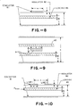
- Figure 8 shows a strip line consisting of a ground conductor and upper signal conductor 81 on opposite sides of an insulator 82, and a layer of magnetic material 83 which provides the inductance, in the insulator 82.
- Figure 9 shows a similar arrangement but with a magnetic layer 83 on both sides of the signal conductor 81.
- Figure 10 shows another magnetically loaded strip line comprising two singal lines I, II on a loaded insulator 82, which can be coupled or uncoupled depending on the permeability of the magnetic material layer 83.
- H H bias
- the implications are very many for applications such as breadboard design and microwave integrated circuits.
- the arrangement can be applied to a variety of complex interconnection patterns depending on the geometry of the embedded magnetic material layer 83.
- the insulator substrate 82 may be layered, uniformly doped or have any suitable loading geometry.
- the magnetic material layer 83 may be at variable positions "x" and may have variable thickness "d".
- the provided inductance depends weakly on the position-x and not very strongly on the thickness-d.
Landscapes
- Physics & Mathematics (AREA)
- General Physics & Mathematics (AREA)
- Optics & Photonics (AREA)
- Communication Cables (AREA)
- Waveguides (AREA)
Applications Claiming Priority (2)
| Application Number | Priority Date | Filing Date | Title |
|---|---|---|---|
| US06/899,714 US4843356A (en) | 1986-08-25 | 1986-08-25 | Electrical cable having improved signal transmission characteristics |
| US899714 | 1986-08-25 |
Publications (2)
| Publication Number | Publication Date |
|---|---|
| EP0258028A2 true EP0258028A2 (de) | 1988-03-02 |
| EP0258028A3 EP0258028A3 (de) | 1988-11-17 |
Family
ID=25411451
Family Applications (1)
| Application Number | Title | Priority Date | Filing Date |
|---|---|---|---|
| EP87307465A Withdrawn EP0258028A3 (de) | 1986-08-25 | 1987-08-24 | Elektrische Kabel |
Country Status (3)
| Country | Link |
|---|---|
| US (1) | US4843356A (de) |
| EP (1) | EP0258028A3 (de) |
| JP (1) | JPS63146306A (de) |
Cited By (4)
| Publication number | Priority date | Publication date | Assignee | Title |
|---|---|---|---|---|
| WO1991016648A1 (en) * | 1990-04-26 | 1991-10-31 | Nkf Kabel B.V. | Cladding structure, in particular for optical cables, for use in high-voltage environments |
| WO1993024942A1 (de) * | 1992-06-01 | 1993-12-09 | Siemens Aktiengesellschaft | Elektrische hochspannungs-schaltanlage mit wenigstens einem sensor |
| WO1994024596A1 (en) * | 1993-04-22 | 1994-10-27 | Bicc Public Limited Company | Optical cable |
| WO2008043349A2 (de) | 2006-10-12 | 2008-04-17 | Andreas Max Pavel | Verfahren und vorrichtung zur aufnahme, übertragung und wiedergabe von schallereignissen für kommunikationsanwendungen |
Families Citing this family (25)
| Publication number | Priority date | Publication date | Assignee | Title |
|---|---|---|---|---|
| US5191304A (en) * | 1990-03-02 | 1993-03-02 | Orion Industries, Inc. | Bandstop filter having symmetrically altered or compensated quarter wavelength transmission line sections |
| US5257157A (en) * | 1990-05-04 | 1993-10-26 | Epstein Barry M | Protector network for A-C equipment |
| FR2682547A1 (fr) * | 1991-10-15 | 1993-04-16 | Alcatel Nv | Liaison a fibres optiques amplificatrices. |
| JP3344695B2 (ja) * | 1997-07-29 | 2002-11-11 | 株式会社村田製作所 | ノイズ抑制部品 |
| JP3277854B2 (ja) * | 1997-08-08 | 2002-04-22 | 株式会社村田製作所 | ノイズ抑制機能付き絶縁被覆電線 |
| AU4956799A (en) * | 1998-06-22 | 2000-01-10 | Rafael Elul | Transmission of power and signals over coaxial cable, twisted pair cable, and other electric cables |
| US6570087B2 (en) * | 1999-05-25 | 2003-05-27 | Autosound 2000, Inc. | Delta magnetic de-fluxing for low noise signal cables |
| JP4000729B2 (ja) * | 1999-12-15 | 2007-10-31 | 日立電線株式会社 | 同軸ケーブル及びその製造方法 |
| DE10013936A1 (de) * | 2000-03-21 | 2001-09-27 | Bodenseewerk Geraetetech | Filteranordnung |
| US6576843B1 (en) | 2000-07-17 | 2003-06-10 | Brookhaven Science Associates, Llc | Power superconducting power transmission cable |
| US7075308B2 (en) * | 2003-03-12 | 2006-07-11 | Rockwell Daniel J | Blocking impedance |
| SE527008C2 (sv) * | 2003-11-07 | 2005-12-06 | Abb Research Ltd | System för överföring av elektrisk kraft |
| US6998538B1 (en) * | 2004-07-30 | 2006-02-14 | Ulectra Corporation | Integrated power and data insulated electrical cable having a metallic outer jacket |
| US7208684B2 (en) * | 2004-07-30 | 2007-04-24 | Ulectra Corporation | Insulated, high voltage power cable for use with low power signal conductors in conduit |
| DE102004043020B3 (de) * | 2004-09-06 | 2006-04-27 | eupec Europäische Gesellschaft für Leistungshalbleiter mbH | Bonddraht und Bondverbindung |
| US7572981B2 (en) * | 2005-09-14 | 2009-08-11 | Illinois Tool Works Inc. | Parked aircraft power cable protection system and method |
| RU2347304C2 (ru) * | 2006-06-13 | 2009-02-20 | Александр Владимирович Ян-Белявский | Способ повышения качества аудиосигнала в токопроводящем кабеле (варианты), токопроводящий кабель и токопроводящая жила для этого кабеля |
| DE102006038138A1 (de) * | 2006-08-16 | 2008-02-21 | Adc Gmbh | Symmetrisches Datenkabel für die Kommunikations- und Datentechnik |
| RU2345451C1 (ru) * | 2007-04-06 | 2009-01-27 | Александр Владимирович Ян-Беляевский | Регулируемый аудиокабель с расширенным диапазоном регулировки тонального баланса (варианты) и токопроводящая жила для этого кабеля |
| WO2013173135A1 (en) * | 2012-05-14 | 2013-11-21 | Microsemi Corporation | Power over ethernet for bi-directional ethernet over single pair |
| US9450389B2 (en) | 2013-03-05 | 2016-09-20 | Yaroslav A. Pichkur | Electrical power transmission system and method |
| JP6245043B2 (ja) * | 2014-04-02 | 2017-12-13 | 日立金属株式会社 | ノイズ抑制ケーブル |
| US10923267B2 (en) | 2014-09-05 | 2021-02-16 | Yaroslav A. Pichkur | Transformer |
| FR3116646B1 (fr) * | 2020-11-26 | 2023-06-30 | Thales Sa | Câble de puissance à filtre intégré |
| US20230326628A1 (en) * | 2022-04-06 | 2023-10-12 | Berk-Tek Llc | Isolation wrap with choke |
Family Cites Families (18)
| Publication number | Priority date | Publication date | Assignee | Title |
|---|---|---|---|---|
| BE428242A (de) * | 1937-05-24 | |||
| FR1047856A (fr) * | 1951-06-29 | 1953-12-17 | Lignes Telegraph Telephon | Circuits de télécommunication avec charge magnétique |
| US2787656A (en) * | 1954-12-30 | 1957-04-02 | Bell Telephone Labor Inc | Magnetically loaded conductors |
| US3082387A (en) * | 1959-07-23 | 1963-03-19 | Pirelli | Multi-conductor telecommunication cables for audio and carrier frequencies |
| DE1200393B (de) * | 1961-09-15 | 1965-09-09 | Telefunken Patent | Leitungskreis mit auf beiden Seiten einer Isolierstoffschicht aufgebrachten Leitern |
| FR80097E (fr) * | 1961-07-13 | 1963-03-08 | Electricfil | Fil électrique antiparasite |
| DE1159057B (de) * | 1961-07-25 | 1963-12-12 | Siemens Ag | Fernmeldekabel mit um einen Kern in Lagen angeordneten Einzeladern, aus denen durch gegenseitiges systematisches Kreuzen Doppelleitungen und aus den Doppelleitungen Phantomkreise gebildet sind |
| GB1335580A (en) * | 1970-03-20 | 1973-10-31 | Yazaki Corp | High frequency noise prevention cable |
| US3688224A (en) * | 1971-05-14 | 1972-08-29 | Kunihiro Suetake | Electric source filter |
| US4017344A (en) * | 1973-03-05 | 1977-04-12 | Harold Lorber | Magnetically enhanced coaxial cable with improved time delay characteristics |
| DE2461611A1 (de) * | 1974-12-27 | 1976-07-08 | Holm Dipl Ing Benndorf | Kombiniertes informationsuebertragungs- und hochspannungsfreileitungsseil mit kuenstlich erhoehtem induktivitaetsbelag der fernmelde-verseilelemente fuer die informationsuebertragung in elektrizitaetsversorgungsnetzen |
| FR2437686A1 (fr) * | 1978-09-29 | 1980-04-25 | Mayer Ferdy | Element electrique a pertes, tel que fil, cable et ecran, resistant et absorbant |
| FR2461342A1 (fr) * | 1979-07-06 | 1981-01-30 | Mayer Ferdy | Cables a haute immunite, contre pulse electromagnetique (emp) |
| US4399419A (en) * | 1980-03-20 | 1983-08-16 | Zenith Radio Corporation | Line isolation and interference shielding for a shielded conductor system |
| US4347487A (en) * | 1980-11-25 | 1982-08-31 | Raychem Corporation | High frequency attenuation cable |
| US4486721A (en) * | 1981-12-07 | 1984-12-04 | Raychem Corporation | High frequency attenuation core and cable |
| US4510468A (en) * | 1982-09-30 | 1985-04-09 | Ferdy Mayer | RF Absorptive line with controlled low pass cut-off frequency |
| US4539433A (en) * | 1982-11-24 | 1985-09-03 | Tdk Corporation | Electromagnetic shield |
-
1986
- 1986-08-25 US US06/899,714 patent/US4843356A/en not_active Expired - Fee Related
-
1987
- 1987-08-24 EP EP87307465A patent/EP0258028A3/de not_active Withdrawn
- 1987-08-25 JP JP62211206A patent/JPS63146306A/ja active Pending
Cited By (6)
| Publication number | Priority date | Publication date | Assignee | Title |
|---|---|---|---|---|
| WO1991016648A1 (en) * | 1990-04-26 | 1991-10-31 | Nkf Kabel B.V. | Cladding structure, in particular for optical cables, for use in high-voltage environments |
| US5317665A (en) * | 1990-04-26 | 1994-05-31 | Nkf Kabel B.V. | Jacket structure for optical cables, for use in high-voltage environments |
| WO1993024942A1 (de) * | 1992-06-01 | 1993-12-09 | Siemens Aktiengesellschaft | Elektrische hochspannungs-schaltanlage mit wenigstens einem sensor |
| WO1994024596A1 (en) * | 1993-04-22 | 1994-10-27 | Bicc Public Limited Company | Optical cable |
| US5606636A (en) * | 1993-04-22 | 1997-02-25 | Bicc Public Limited Company | Optical cable for avoiding dry-band arcing |
| WO2008043349A2 (de) | 2006-10-12 | 2008-04-17 | Andreas Max Pavel | Verfahren und vorrichtung zur aufnahme, übertragung und wiedergabe von schallereignissen für kommunikationsanwendungen |
Also Published As
| Publication number | Publication date |
|---|---|
| EP0258028A3 (de) | 1988-11-17 |
| JPS63146306A (ja) | 1988-06-18 |
| US4843356A (en) | 1989-06-27 |
Similar Documents
| Publication | Publication Date | Title |
|---|---|---|
| US4843356A (en) | Electrical cable having improved signal transmission characteristics | |
| US6005193A (en) | Cable for transmitting electrical impulses | |
| US5777273A (en) | High frequency power and communications cable | |
| US4383225A (en) | Cables with high immunity to electro-magnetic pulses (EMP) | |
| JP4372845B2 (ja) | 電力変圧器/誘導器 | |
| US20010042632A1 (en) | Filter for wire and cable | |
| US5132490A (en) | Conductive polymer shielded wire and cable | |
| JP4372844B2 (ja) | 電力変圧器/誘導器 | |
| GB2033645A (en) | Lossy electric element such as wire cable or screen resistant and absorbent | |
| JPH05140368A (ja) | 遮蔽材及び遮蔽電線・ケーブル製品 | |
| US7060905B1 (en) | Electrical cable having an organized signal placement and its preparation | |
| EP1361587A1 (de) | EMI-Filter | |
| CA2180983C (en) | Silver ribbon cable | |
| US4760362A (en) | Leaky coaxial cable providing inductive coupling by eliminating radiating gaps, and the method of making same | |
| US1672979A (en) | Loaded conductor | |
| WO1992001301A1 (en) | High velocity propagation ribbon cable | |
| US11929536B2 (en) | Filter cable | |
| JP2579583B2 (ja) | 高周波信号線路 | |
| US3018452A (en) | Helix wave guide | |
| KR20010032560A (ko) | 방사 케이블 | |
| JPS6243603B2 (de) | ||
| GB2366068A (en) | Reducing RF-induced longitudinal currents in conductors | |
| JPS58134506A (ja) | 開放型同軸ケ−ブル | |
| WO2000039820A1 (en) | A high voltage transformer | |
| JPS60117506A (ja) | 高周波除去シ−ルドケ−ブル |
Legal Events
| Date | Code | Title | Description |
|---|---|---|---|
| PUAI | Public reference made under article 153(3) epc to a published international application that has entered the european phase |
Free format text: ORIGINAL CODE: 0009012 |
|
| AK | Designated contracting states |
Kind code of ref document: A2 Designated state(s): DE FR GB IT |
|
| PUAL | Search report despatched |
Free format text: ORIGINAL CODE: 0009013 |
|
| AK | Designated contracting states |
Kind code of ref document: A3 Designated state(s): DE FR GB IT |
|
| STAA | Information on the status of an ep patent application or granted ep patent |
Free format text: STATUS: THE APPLICATION IS DEEMED TO BE WITHDRAWN |
|
| 18D | Application deemed to be withdrawn |
Effective date: 19890518 |
|
| RIN1 | Information on inventor provided before grant (corrected) |
Inventor name: LUSIGNAN, BRUCE B. Inventor name: DADAKARIDES, SIMOS D. |