EP0258041A2 - Transmission à courroie pour bicyclette - Google Patents
Transmission à courroie pour bicyclette Download PDFInfo
- Publication number
- EP0258041A2 EP0258041A2 EP87307519A EP87307519A EP0258041A2 EP 0258041 A2 EP0258041 A2 EP 0258041A2 EP 87307519 A EP87307519 A EP 87307519A EP 87307519 A EP87307519 A EP 87307519A EP 0258041 A2 EP0258041 A2 EP 0258041A2
- Authority
- EP
- European Patent Office
- Prior art keywords
- gear
- crank
- gear means
- driving
- wheel
- Prior art date
- Legal status (The legal status is an assumption and is not a legal conclusion. Google has not performed a legal analysis and makes no representation as to the accuracy of the status listed.)
- Granted
Links
Images



Classifications
-
- B—PERFORMING OPERATIONS; TRANSPORTING
- B62—LAND VEHICLES FOR TRAVELLING OTHERWISE THAN ON RAILS
- B62M—RIDER PROPULSION OF WHEELED VEHICLES OR SLEDGES; POWERED PROPULSION OF SLEDGES OR SINGLE-TRACK CYCLES; TRANSMISSIONS SPECIALLY ADAPTED FOR SUCH VEHICLES
- B62M9/00—Transmissions characterised by use of an endless chain, belt, or the like
- B62M9/04—Transmissions characterised by use of an endless chain, belt, or the like of changeable ratio
- B62M9/06—Transmissions characterised by use of an endless chain, belt, or the like of changeable ratio using a single chain, belt, or the like
- B62M9/08—Transmissions characterised by use of an endless chain, belt, or the like of changeable ratio using a single chain, belt, or the like involving eccentrically- mounted or elliptically-shaped driving or driven wheel; with expansible driving or driven wheel
-
- B—PERFORMING OPERATIONS; TRANSPORTING
- B62—LAND VEHICLES FOR TRAVELLING OTHERWISE THAN ON RAILS
- B62M—RIDER PROPULSION OF WHEELED VEHICLES OR SLEDGES; POWERED PROPULSION OF SLEDGES OR SINGLE-TRACK CYCLES; TRANSMISSIONS SPECIALLY ADAPTED FOR SUCH VEHICLES
- B62M9/00—Transmissions characterised by use of an endless chain, belt, or the like
-
- B—PERFORMING OPERATIONS; TRANSPORTING
- B62—LAND VEHICLES FOR TRAVELLING OTHERWISE THAN ON RAILS
- B62M—RIDER PROPULSION OF WHEELED VEHICLES OR SLEDGES; POWERED PROPULSION OF SLEDGES OR SINGLE-TRACK CYCLES; TRANSMISSIONS SPECIALLY ADAPTED FOR SUCH VEHICLES
- B62M9/00—Transmissions characterised by use of an endless chain, belt, or the like
- B62M9/04—Transmissions characterised by use of an endless chain, belt, or the like of changeable ratio
- B62M9/06—Transmissions characterised by use of an endless chain, belt, or the like of changeable ratio using a single chain, belt, or the like
-
- Y—GENERAL TAGGING OF NEW TECHNOLOGICAL DEVELOPMENTS; GENERAL TAGGING OF CROSS-SECTIONAL TECHNOLOGIES SPANNING OVER SEVERAL SECTIONS OF THE IPC; TECHNICAL SUBJECTS COVERED BY FORMER USPC CROSS-REFERENCE ART COLLECTIONS [XRACs] AND DIGESTS
- Y10—TECHNICAL SUBJECTS COVERED BY FORMER USPC
- Y10T—TECHNICAL SUBJECTS COVERED BY FORMER US CLASSIFICATION
- Y10T74/00—Machine element or mechanism
- Y10T74/21—Elements
- Y10T74/2164—Cranks and pedals
- Y10T74/2165—Cranks and pedals with attached gear
Definitions
- This invention relates to a belt driven bicycle, and more particularly to an apparatus for driving such a belt.
- Fig.7 shows a conventional belt driving apparatus for a bicycle. More specifically, this belt driving apparatus comprises a driving pulley 2 of large diameter mounted on a crank shaft 1 and a driven pulley 3 of small diameter mounted on a shaft on the side of a rear wheel a toothed belt 4 being traind over the driving and driven pulleys 2.3.
- this belt driving apparatus fabricated as abovementioned idlers 5a. 5a which are close to each other urge the toothed belt 4 such as to apply a certain tensile force thereto in order to prevent the toothed belt 4 from being removed or slipping.
- the toothed belt 4 if urged by the idlers 5a. 5a is rotated and driven while being in a curved condition in the position where the idler 5a is located and the belt 4 is therefore greatly damaged. This requires the belt to be replaced after a short time.
- Fig.8 shows another conventional belt driving apparatus which comprises a driving gear 6 mounted on the crank shaft 1, a floating wheel 7 with internal teeth 7a which meshes with the driving gear 6, and a toothed belt 4 trained over the floating wheel 7 for rotatably driving the driven pulley 3.
- the belt driving apparatus arranged as aforementioned is required to secure the rotational speed of the driven pulley 3 by use of the driving gear 6 and a floating wheel 7, each of large diameter, since the floating wheel 7 is reducedly driven by the driving gear 6.
- the disadvantage derived from the use of the driving gear 6 and the floating wheel 7 of large diameter is that the weight of the bicycle is increased.
- the internal teeth 7a in a position adjacent to a point A of the floating wheel 7 is disengaged from the teeth of the driving gear 6 or goes out of mesh therewith due to the inconsistent extent of eccentricity of the floating wheel 7 when the pedals are worked energetically. This may possibly cause damage to the teeth.
- the first invention is characterized in that an inner gear means is provided with in the interior of an outer gear means over which a toothed belt is trained such as to form a driving gear, the inner gear means being in mesh with a crank gear which is mounted on a crank shaft and provived on its inner periphery with teeth.
- the second invention is characterized in that an inner gear means is provided within the interior of an outer gear means over which a toothed belt is trained such as to form a driving gear, the inner gear means being in mesh with a crank gear which is mounted on a crank shaft and is provided on its inner periphery with teeth, and that a control plate is rotatbly arranged between an inner wheel disposed coaxially of the crank gear and an outer wheel located coaxially of the driving gear and is eccentric relative to the inner wheel by a predetermined extent such as to control the eccentricity of the driving gear.
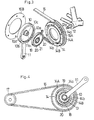
- a belt driving apparatus for a bicycle includes a crank gear 10 as shown in Figs.1 and 2.
- the crank gear 10 is provided on its inner periphery with teeth 10a and includes a side wall 10b integrally formed therewith.
- the side wall 10b is formed at its center with a square opening 10c into which is inserted a square fitting means 11a projected from one end of the crank arm 11.
- the fitting means 11a is fitted over a square crank shaft 12, and a cap 13 is screwed around a thread 12a at the forward end of the crank shaft 12.
- a pedal (not shown) is fixed to the other end of the crank arm 11.
- a driving gear 14 driven by the crank gear 10 includes an outer gear means 14A of large diameter.
- the outer gear means 14A is provided on its outer periphery with teeth 14a and carries a toothed belt 15 trained thereover.
- the outer gear means 14A has formed in its interior an inner gear means 14B coaxially therewith.
- the inner gear means 14B is formed such that its diameter is somewhat smaller than that of the crank gear 10 and is provided on it outer periphery with teeth 14b.
- a cover member 16A is integrally formed with the outer and inner gear means 14A and 14B on one of the end faces thereof. Another cover member 16B disposed between the crank arm 11 and the crank gear 10 is bolted to the outer gear means 14A at the other end thereof.
- the crank gear 10 is located between the outer and inner gear means 14A and 14B so that its teeth 10a mesh with the teeth 14b of the inner gear means 14B.
- the toothed belt 15 is made of rubber containing Kevlars fibers and is trained over the outer gear means 14A and a driven pulley 17.
- the belt driving apparatus as above arranged when the crank arm 11 is rotated by working the pedals to thereby rotate the crank gear 10 so that the driving gear 14 is made eccentric and moved by means of the inner gear means 14B in mesh with the crank gear for applying a predetermined tensile force to the toothed belt 15, the inner gear means 14B is then rotated by means of the crank gear 10 to thus rotatably drive the toothed belt 15 by means of the outer gear means 14A.
- the toothed belt 15 may be rotatably driven without being bent and is not damaged even if it is used for a long period of time.
- the inner gear means 14B of somewhat smaller diameter is eccentric and rotated by means of the crank gear 10 to thereby increase the rotational speed of the outer gear means 14A.
- the driven pulley 17 may be rotated at a predetermined speed to enable the driven pulley 17 to rotate at a predetermined speed without the outer diameter and dimension of the outer gear means 14 needing to be increased so much. This minimizes the weight of the driving gear as a whole such as to lighten the apparatus itself.
- the differences in outer diameter and dimension between the crank gear 10 and the inner gear means 14B are small so that generation of noise is avoided.
- Fig.3 and 4 show another belt driving apparatus according to the second invention, which includes the crank gear 10.
- the crank gear 10 is provided on its inner periphery with teeth 10a and includes a side wall 10b formed integrally with the crank gear 10.
- a boss 10d extends from the center of the side wall 10b and is formed with a square opening 10c into which is inserted the fitting means 11a in a square form projected from the crank arm 11 at one end thereof.
- the fitting means 11a is in turn fitted over the square crank shaft 12.
- the cap 13 is screwed onto the thread 12 formed at the forward end of the crank shaft 12.
- the pedal (not shown) is attached to the other end of the crank arm 11.
- the driving gear 14 driven by the crank gear 10 includes the outer gear means 14A of large diameter.
- the outer gear means 14A is formed on its outer periphery with the teeth 14a over which the toothed belt 15 is trained.
- the inner gear means 14B is disposed with in the interior of the outer gear means 14A to be coaxial therewith.
- the inner gear means 14B is provided with a diameter which is rather small and has the teeth 14b formed on its outer periphery.
- the cover 16 is formed integrally with the outer and inner gear means 14A and 14B at one end face thereof.
- the other cover member 16B which covers the crank gear 10 interiorly of the crank arm 11 is bolted to the outer gear means at the other end face thereof.
- the crank gear 10 is located between the outer and inner gear means 14A and 14B to allow its teeth 10a to mesh with the teeth 14b of the inner gear means 14B.
- the inner wheel 18 of small diameter abuts against the boss 10d of the crank gear 10.
- the outer wheel 19 of large diameter is mounted within the inner periphery of the inner gear means 14B.
- An eccentricity control plate 21 is rotatably located over a bearing 20 and between the inner and outer wheels 18 and 19.
- the control plate 21 is eccentric relative tO the inner wheel 18 by a predetermined extent.
- the toothed belt 15 is formed of a rubber member containing Kevlar fiber and is trained over the outer gear means 14A and the driven pulley 17.
- the toothed belt 15 as shown in Fig.5A if it is of a sufficient length, renders the inner gear section 14B of the driving gear 14 eccentric in the leftward direction and downwardly relative to the crank gear 10, its teeth 14b thereby being meshed with the teeth 10a of the crank gear 10.
- the control plate 21 is eccentric leftwardly and downwardly relative to the inner wheel 18 as shown in Fig.6A
- crank gear 10 At the beginning of working the pedals, rotation of the crank gear 10 is initiated so that the inner gear means 14B meshes with the crank gear 10 and is thereby made eccentric leftwardly and upwardly relative to the crank gear 10, as shown Fig.5B.
- the control plate 21 is also eccentric leftwardly and upwardly relative to the inner wheel 8 (crank gear 10), as shown in Fig.6B, since thhe outer wheel 19 as well as the inner gear means 14B is eccentric and rotated therewith.
- the inner gear means 14B When the pedals are fully worked and the bicycle is running, the inner gear means 14B, as shown in Fig.5C, is eccentric to the right of the crank gear 10 and adjacent to the center thereof and thereby moves the outer gear means 14A forwardly in the direction in which the latter is running, thereby applying tensile force to the toothed belt 15. Consequently, the inner gear means 14B is rotated by the rotation of the crank gear 10 so that the outer gear means 14A is caused to rotatably drive the toothed belt 15.
- the control plate 21, as shown in Fig.6C is in turn eccentric to the right of the inner wheel 18 and adjacent to the center thereof and is then located in that position.
- the toothed belt 15 may be rotatably driven without being bent even if it is subjected to tensile force due to the eccentric movement of the driving gear 14. For this reason, the toothed belt 15 is not damaged even if it is used over a long period of time.
- the inner gear means 14B of small diameter is eccentric in relation to and is rotated by the crank gear 10 to thus increase the rotational speed of the outer gear means 14.
- the driven pulley 17 may be rotated at a predetermined sped without requiring the outer diameter and dimension of the outer gear means 14A to be increased so much. This minimizes the weight of the driving gear 14 as a whole and renders the instant apparatus light.
- the toothed belt 15 be reduced in length and dimension but there is also a small difference in the outer diameter and dimension of the crank gear 10 and the inner gear means 14B, thereby avoiding generation of noise.
- the extent of eccentricity of the inner gear means 14B relative to the crank gear 10 is limited to a given value by the control plate 21 so that the teeth 14b of the inner gear means 14B positively mesh with the teeth of the crank gear 10 and are thus eccentric to the position shown in Fig.5C.
- the teeth 10a of the crank gear 10 are, therefore, prevented from being disengaged from the teeth 14b of the inner gear means 14B and thus no damage of these teeth 10a, 14a occurs.
- the area in which the inner gear means 14B covers a range of about 180 (see the angle) is large, as shown in Fig. 5C. This allows the pedals to be worked smoothly and tensile force to be exerted on the toothed belt 15 to thus remarkably minimize expansion and damage thereof.
- the inner gear means 14B (driving gear 14) is eccentrically moved to the maximum extent 1.
- gear accuracy is not required in setting the length and dimension of the toothed belt 15, and the operations required for training the toothed belt 15 over the driving gear 14 and the like are thus facilitated.
- the toothed belt 15 may be rotatably driven even if it becomes stretched due to long use since driving gear 14 is moved to a greater extent such as to accommodate such stretching.
- the inner wheel 18 may be secured to the crank shaft 12 so long as it is disposed coaxially with the crank gear 10.
- the outer wheel 16 may be fixed to the cover member 16A or 16B so long as the arrangement is such that eccentricity of the driving gear 14 is controlled by the control plate 21.
- the driving gear is composed of the outer gear means over which the toothed belt is trained, and the inner gear means which mesh with the teeth formed in the inner periphery of the crank gear attached to the crank shaft so that not only may the toothed belt be rotatably driven without being bent but also the rear wheel may be rotated while assuring its rotational speed without any need to increase the dimension of the driving gear, thereby avoiding generation of noise.
- a belt driving apparatus which is capable of using a toothed belt for a long period of time and of reducing the weight of the bicycle and the noise produced thereby.
- the driving gear is composed of the outer gear means over which the toothed belt is trained, and the inner gear means which meshes with the teeth formed in the inner periphery of the crank gear attached to the crank shaft, and the eccentric control plate is interposed between the inner wheel which is rotatable coaxially and the integrally with the crank gear and the outer wheel mounted in the inner gear means such as to limit the extent of the eccentricity of the driving gear to a predetermined value so that not only may toothed belt be rotatably driven without being bent but also the rear wheel may be rotated while assuring its rotatinal speed without any need to increase the dimension of the driving gear, thereby avoiding generation of noise.
Landscapes
- Engineering & Computer Science (AREA)
- Chemical & Material Sciences (AREA)
- Combustion & Propulsion (AREA)
- Transportation (AREA)
- Mechanical Engineering (AREA)
- Devices For Conveying Motion By Means Of Endless Flexible Members (AREA)
- Transmission Devices (AREA)
- General Details Of Gearings (AREA)
Applications Claiming Priority (4)
| Application Number | Priority Date | Filing Date | Title |
|---|---|---|---|
| JP199384/86 | 1986-08-26 | ||
| JP61199384A JP2542196B2 (ja) | 1986-08-26 | 1986-08-26 | 自転車用ベルト駆動装置 |
| JP280145/86 | 1986-11-25 | ||
| JP61280145A JP2542203B2 (ja) | 1986-11-25 | 1986-11-25 | 自転車用ベルト駆動装置 |
Publications (3)
| Publication Number | Publication Date |
|---|---|
| EP0258041A2 true EP0258041A2 (fr) | 1988-03-02 |
| EP0258041A3 EP0258041A3 (en) | 1989-02-15 |
| EP0258041B1 EP0258041B1 (fr) | 1990-06-06 |
Family
ID=26511508
Family Applications (1)
| Application Number | Title | Priority Date | Filing Date |
|---|---|---|---|
| EP87307519A Expired - Lifetime EP0258041B1 (fr) | 1986-08-26 | 1987-08-25 | Transmission à courroie pour bicyclette |
Country Status (5)
| Country | Link |
|---|---|
| US (1) | US4768998A (fr) |
| EP (1) | EP0258041B1 (fr) |
| KR (1) | KR920001423B1 (fr) |
| CA (1) | CA1291653C (fr) |
| DE (1) | DE3763043D1 (fr) |
Cited By (8)
| Publication number | Priority date | Publication date | Assignee | Title |
|---|---|---|---|---|
| EP0305129B1 (fr) * | 1987-08-27 | 1992-10-07 | Bridgestone Cycle Co., Ltd. | Dispositif de transmission inscrit |
| DE4403464A1 (de) * | 1994-02-04 | 1995-08-10 | Dietrich Gerhard Ellsaeser | Fahrrad mit wartungsfreiem Antrieb |
| WO2006038241A1 (fr) * | 2004-10-05 | 2006-04-13 | Calabrian High Tech Srl | Systeme de transmissions pour vehicules a pedales avec engrenement non cylindrique |
| DE102007044078A1 (de) * | 2007-09-14 | 2009-04-02 | Clean Mobile Gmbh | Außenläufer-Elektromotor mit Planetengetriebe, Kraftfahrzeug mit Außenläufer-Elektromotor und Verfahren zum Betreiben eines solchen Fahrzeugs |
| CN102328723A (zh) * | 2010-07-12 | 2012-01-25 | 柏彰科技股份有限公司 | 皮带式脚踏车的传动装置 |
| DE202008018341U1 (de) | 2007-07-18 | 2013-02-14 | Clean Mobile Ag | Außenläufer-Elektromotor mit oder ohne Planetengetriebe, sowie Kraftfahrzeug mit Außenläufer-Elektromotor |
| TWI624402B (zh) * | 2017-05-08 | 2018-05-21 | Wang sheng bin | Bicycle transmission |
| CN111375190A (zh) * | 2019-12-31 | 2020-07-07 | 惠州真骐自行车有限公司 | 一种液压驱动的移动轴心 |
Families Citing this family (11)
| Publication number | Priority date | Publication date | Assignee | Title |
|---|---|---|---|---|
| US4936812A (en) * | 1988-08-05 | 1990-06-26 | The Gates Rubber Company | Torque reactive tension mechanism and method |
| US5221236A (en) * | 1990-07-10 | 1993-06-22 | Raymer Matthew C | Belt tensioning device for belt driven bicycle |
| US5755635A (en) * | 1993-01-28 | 1998-05-26 | Draco Limited | Crank device for the transmission of energy with elimination of dead centers, particularly suited for bicycles and the like |
| US20040127318A1 (en) * | 2002-12-27 | 2004-07-01 | Aeon Motor Co., Ltd. | Chain tensing device for an engine gear |
| JP4145158B2 (ja) * | 2003-02-03 | 2008-09-03 | 株式会社ジェイテクト | 電動パワーステアリング装置 |
| DE102004031418A1 (de) * | 2004-06-29 | 2006-02-16 | Rumpf, Paul | Kurbeltriebmomentwandler, zur Drehmomentsteuerung der Drehkraftaufnahme und Drehkraftübertragung von Kurbeltriebe |
| US20070151794A1 (en) * | 2004-12-28 | 2007-07-05 | Nsk Ltd. | Electric power steering apparatus |
| US9222568B2 (en) | 2011-01-05 | 2015-12-29 | Trek Bicycle Corporation | Bicycle power train cogs |
| USD655225S1 (en) | 2011-01-05 | 2012-03-06 | Trek Bicycle Corporation | Bicycle cog |
| USD733009S1 (en) * | 2011-05-02 | 2015-06-30 | Julian E. Woods | Crank arm and chainring assembly for a bicycle |
| JP7548057B2 (ja) * | 2021-02-25 | 2024-09-10 | 京セラドキュメントソリューションズ株式会社 | シート収納装置、およびシート収納装置を備える画像形成ユニット |
Family Cites Families (5)
| Publication number | Priority date | Publication date | Assignee | Title |
|---|---|---|---|---|
| US631208A (en) * | 1898-01-24 | 1899-08-15 | David C Frazeur | Gearing. |
| FR2426193A1 (fr) * | 1978-05-16 | 1979-12-14 | Kawagishi Ichiro | Dispositif de transmission a changement de vitesse, notamment pour bicyclette |
| FR2479767A1 (fr) * | 1980-04-02 | 1981-10-09 | Noussy Andre | Pedalier surmultiplie pour bicyclette |
| US4412828A (en) * | 1981-05-07 | 1983-11-01 | Darby Jack B | Control means for shifting gears on dual shift bicycles |
| US4599079A (en) * | 1985-03-04 | 1986-07-08 | Chappell Gilmore H | Automatic derailleur shifter |
-
1987
- 1987-05-14 US US07/049,820 patent/US4768998A/en not_active Expired - Fee Related
- 1987-08-25 DE DE8787307519T patent/DE3763043D1/de not_active Expired - Fee Related
- 1987-08-25 CA CA000545256A patent/CA1291653C/fr not_active Expired - Fee Related
- 1987-08-25 EP EP87307519A patent/EP0258041B1/fr not_active Expired - Lifetime
- 1987-08-26 KR KR1019870009318A patent/KR920001423B1/ko not_active Expired
Cited By (9)
| Publication number | Priority date | Publication date | Assignee | Title |
|---|---|---|---|---|
| EP0305129B1 (fr) * | 1987-08-27 | 1992-10-07 | Bridgestone Cycle Co., Ltd. | Dispositif de transmission inscrit |
| DE4403464A1 (de) * | 1994-02-04 | 1995-08-10 | Dietrich Gerhard Ellsaeser | Fahrrad mit wartungsfreiem Antrieb |
| WO2006038241A1 (fr) * | 2004-10-05 | 2006-04-13 | Calabrian High Tech Srl | Systeme de transmissions pour vehicules a pedales avec engrenement non cylindrique |
| DE202008018341U1 (de) | 2007-07-18 | 2013-02-14 | Clean Mobile Ag | Außenläufer-Elektromotor mit oder ohne Planetengetriebe, sowie Kraftfahrzeug mit Außenläufer-Elektromotor |
| DE102007044078A1 (de) * | 2007-09-14 | 2009-04-02 | Clean Mobile Gmbh | Außenläufer-Elektromotor mit Planetengetriebe, Kraftfahrzeug mit Außenläufer-Elektromotor und Verfahren zum Betreiben eines solchen Fahrzeugs |
| CN102328723A (zh) * | 2010-07-12 | 2012-01-25 | 柏彰科技股份有限公司 | 皮带式脚踏车的传动装置 |
| TWI624402B (zh) * | 2017-05-08 | 2018-05-21 | Wang sheng bin | Bicycle transmission |
| CN111375190A (zh) * | 2019-12-31 | 2020-07-07 | 惠州真骐自行车有限公司 | 一种液压驱动的移动轴心 |
| CN111375190B (zh) * | 2019-12-31 | 2021-10-26 | 惠州真骐自行车有限公司 | 一种液压驱动的移动轴心 |
Also Published As
| Publication number | Publication date |
|---|---|
| KR880002715A (ko) | 1988-05-10 |
| EP0258041B1 (fr) | 1990-06-06 |
| EP0258041A3 (en) | 1989-02-15 |
| US4768998A (en) | 1988-09-06 |
| KR920001423B1 (ko) | 1992-02-13 |
| DE3763043D1 (de) | 1990-07-12 |
| CA1291653C (fr) | 1991-11-05 |
Similar Documents
| Publication | Publication Date | Title |
|---|---|---|
| EP0258041A2 (fr) | Transmission à courroie pour bicyclette | |
| FR2405154A1 (fr) | Mecanisme d'entrainement individuel d'une roue pour machines-outils | |
| KR920700094A (ko) | 산업용 로보트의 관절구조 | |
| EP1155953A3 (fr) | Dispositif d'entraínement pour une bicyclette | |
| EP1365176A3 (fr) | Appareil entraíné par moteur | |
| GB2065576A (en) | A drive mechanism for a wheel of a cycle or the like | |
| KR930002895A (ko) | 화상장치의 현상유니트용 기어배열구조 | |
| EP0089129A2 (fr) | Mécanisme de transmission de force avec régulateur de jeu pour robot industriel | |
| BR9602194A (pt) | Dispositivo de alimentação para processar uma folha contínua | |
| JPH06307504A (ja) | 歯厚可変歯車 | |
| JP2542203B2 (ja) | 自転車用ベルト駆動装置 | |
| US5358459A (en) | Mechanic drive apparatus | |
| JP2542196B2 (ja) | 自転車用ベルト駆動装置 | |
| JPS5959390A (ja) | 工業用ロボツトの手首部 | |
| JPH01261534A (ja) | 回転駆動装置 | |
| CN220785901U (zh) | 一种方向盘转动角度检测机构 | |
| JP3365659B2 (ja) | 伝動装置 | |
| US4346621A (en) | Power transmission apparatus | |
| JPS6425159A (en) | Electrophotographic recording device | |
| JPH08171040A (ja) | 撮影レンズの歯車伝動装置 | |
| JPS6456276A (en) | Rear wheel steering device for four-wheel drive type vehicle | |
| JPH0285063U (fr) | ||
| JPH0314946A (ja) | 回転駆動装置 | |
| JPH056049B2 (fr) | ||
| JPH02221750A (ja) | 回転駆動装置 |
Legal Events
| Date | Code | Title | Description |
|---|---|---|---|
| PUAI | Public reference made under article 153(3) epc to a published international application that has entered the european phase |
Free format text: ORIGINAL CODE: 0009012 |
|
| AK | Designated contracting states |
Kind code of ref document: A2 Designated state(s): DE FR GB IT |
|
| PUAL | Search report despatched |
Free format text: ORIGINAL CODE: 0009013 |
|
| AK | Designated contracting states |
Kind code of ref document: A3 Designated state(s): DE FR GB IT |
|
| 17P | Request for examination filed |
Effective date: 19890612 |
|
| 17Q | First examination report despatched |
Effective date: 19890915 |
|
| GRAA | (expected) grant |
Free format text: ORIGINAL CODE: 0009210 |
|
| AK | Designated contracting states |
Kind code of ref document: B1 Designated state(s): DE FR GB IT |
|
| REF | Corresponds to: |
Ref document number: 3763043 Country of ref document: DE Date of ref document: 19900712 |
|
| ITF | It: translation for a ep patent filed | ||
| ET | Fr: translation filed | ||
| PLBE | No opposition filed within time limit |
Free format text: ORIGINAL CODE: 0009261 |
|
| STAA | Information on the status of an ep patent application or granted ep patent |
Free format text: STATUS: NO OPPOSITION FILED WITHIN TIME LIMIT |
|
| 26N | No opposition filed | ||
| ITTA | It: last paid annual fee | ||
| PGFP | Annual fee paid to national office [announced via postgrant information from national office to epo] |
Ref country code: FR Payment date: 19950720 Year of fee payment: 9 |
|
| PGFP | Annual fee paid to national office [announced via postgrant information from national office to epo] |
Ref country code: GB Payment date: 19950815 Year of fee payment: 9 |
|
| PGFP | Annual fee paid to national office [announced via postgrant information from national office to epo] |
Ref country code: DE Payment date: 19950824 Year of fee payment: 9 |
|
| PG25 | Lapsed in a contracting state [announced via postgrant information from national office to epo] |
Ref country code: GB Effective date: 19960825 |
|
| GBPC | Gb: european patent ceased through non-payment of renewal fee |
Effective date: 19960825 |
|
| PG25 | Lapsed in a contracting state [announced via postgrant information from national office to epo] |
Ref country code: FR Effective date: 19970430 |
|
| PG25 | Lapsed in a contracting state [announced via postgrant information from national office to epo] |
Ref country code: DE Effective date: 19970501 |
|
| REG | Reference to a national code |
Ref country code: FR Ref legal event code: ST |
|
| PG25 | Lapsed in a contracting state [announced via postgrant information from national office to epo] |
Ref country code: IT Free format text: LAPSE BECAUSE OF NON-PAYMENT OF DUE FEES;WARNING: LAPSES OF ITALIAN PATENTS WITH EFFECTIVE DATE BEFORE 2007 MAY HAVE OCCURRED AT ANY TIME BEFORE 2007. THE CORRECT EFFECTIVE DATE MAY BE DIFFERENT FROM THE ONE RECORDED. Effective date: 20050825 |