EP0258176A1 - Visier an einer Feuerwaffe - Google Patents
Visier an einer Feuerwaffe Download PDFInfo
- Publication number
- EP0258176A1 EP0258176A1 EP87810419A EP87810419A EP0258176A1 EP 0258176 A1 EP0258176 A1 EP 0258176A1 EP 87810419 A EP87810419 A EP 87810419A EP 87810419 A EP87810419 A EP 87810419A EP 0258176 A1 EP0258176 A1 EP 0258176A1
- Authority
- EP
- European Patent Office
- Prior art keywords
- liquid
- annular space
- window
- visor according
- visor
- Prior art date
- Legal status (The legal status is an assumption and is not a legal conclusion. Google has not performed a legal analysis and makes no representation as to the accuracy of the status listed.)
- Granted
Links
Images

Classifications
-
- F—MECHANICAL ENGINEERING; LIGHTING; HEATING; WEAPONS; BLASTING
- F41—WEAPONS
- F41G—WEAPON SIGHTS; AIMING
- F41G1/00—Sighting devices
- F41G1/46—Sighting devices for particular applications
- F41G1/50—Sighting devices for particular applications for trench mortars or for other mortars
-
- F—MECHANICAL ENGINEERING; LIGHTING; HEATING; WEAPONS; BLASTING
- F41—WEAPONS
- F41G—WEAPON SIGHTS; AIMING
- F41G1/00—Sighting devices
- F41G1/44—Spirit-level adjusting means, e.g. for correcting tilt; Means for indicating or correcting tilt or cant
Definitions
- the present invention relates to a sight on a firearm, in particular on a launcher, for adjusting the elevation of the firearm, with a vessel system surrounding the gun barrel in a ring, in which a free liquid level indicates the elevation.
- a known liquid sight of this type has two diametrically opposite, parallel to the axis of the gun barrel, in which there is a liquid column, and these axially extending spaces are connected at the top and bottom by two lateral annular spaces (communicating tubes / vessels). In one of the axially extending rooms, the liquid column is visible through a window and shows the elevation, which can be read on a scale attached to the window (CH-PS 637 765). Tests have shown that this known visor does not guarantee the required accuracy for certain uses.
- the known liquid visor has a relatively large liquid volume with a relatively small free surface, so that the expansion of the liquid when heated has a similar effect as in a thermometer and significantly falsifies the display.
- a similar inclination indicator with a cylindrical vessel of annular cross-section is known from PATENT ABSTRACTS OF JAPAN, Volume 10, No. 157, JP-A-61 11 609.
- the vessel is partially filled with a conductive liquid and the wall of the vessel is filled with sensors that are influenced by the liquid and connected to a computer that determines the inclination in two dimensions.
- This inclinometer is too expensive for relatively simple weapons.
- the liquid volume in relation to the free liquid surface, and thus the tempera is also in this case dependency significantly.
- a visor which has an annular container on the side of the gun barrel in a plane parallel to the axis of the gun barrel, which is approximately half filled with liquid.
- a scale on the circumference of the container allows the elevation to be read.
- the volume of liquid is large in relation to the free liquid surface and the temperature dependence is therefore considerable.
- the aim of the present invention is to provide a liquid visor of higher accuracy and insensitivity to temperature, which also works with low inertia.
- This goal is achieved in that the vascular system is designed as a coherent annular space, in which the liquid forms a free mirror at least approximately over the entire circumference, and in that the bottom of the annular space is designed as a displacer for reducing the liquid volume.
- the free surface of the liquid present is large, which has the effect that differences in level of this liquid level as a result of heating or cooling move within permissible limits.
- the liquid exchange when the elevation is changed or readjusted can be carried out quickly, so that the display takes place with little inertia and largely without settling.
- the ring-shaped visor 1 is rotatably mounted on a mount 3 of the launcher.
- the carriage 3 with two retractable legs 4 is normally secured by a spring-loaded brake on the tube 2, but can be moved along the tube 2 by pressing a release button 5 in order to change the elevation of the tube.
- the tube is supported on a base plate 6.
- the ring-shaped visor 1 is shown in FIGS. 2-4. It is composed of an inner ring 7 and an outer ring 8, which are tightly connected to one another by means of sealing rings 9 and 10 and are mutually secured by a heavy-duty spring pin 11.
- the inner ring 7 is provided with a circumferential groove 12, the axial length of which is shorter on one side, on the left in FIG. 2, than on the opposite side. In the case of combined rings 7 and 8, this groove forms between them an annular space 13 which is sealed by the seals 9 and 10 and which has a variable axial height corresponding to the groove 12.
- the bottom 14 ⁇ of the annular space 13 lies in a plane which is inclined at an angle E with respect to the axis A of the visor is which corresponds to the minimum elevation of the tube 2. If this minimum elution is 45 ° according to FIG. 1, the plane of the bottom 14 ⁇ is inclined by 45 ° with respect to the axis A.
- the inner ring 7 is provided with cutouts 16. This measure serves to save unnecessary material and weight.
- the outer ring 8 On the side of the bottom section 14 ⁇ , the outer ring 8 has an eye 17 with a window opening 18, in which a transparent window 19 is inserted.
- This window is secured in the window opening by means of securing brackets 20 and sealed against the annular space 13 by means of a seal 21.
- the window opening has a groove 22 at the top and bottom, into which a flexible and opaque cover plate 23 can be snapped.
- Within the window 19 there is a flat luminous element 24 which illuminates the liquid in the annular space 13 and the window 19 and in each case makes the level of the liquid or a scale on the window 19 clearly visible.
- the cover plate 23 not only serves to protect the window 19 but also prevents light from escaping from the luminous element 24 when the weapon is being transported in the dark.
- a suitable liquid of low viscosity is filled into the annular space 13.
- N the level denoted by the window 19 which serves to calibrate the visor. Since the vertical position never corresponds to a fire position, it only serves as a parking or calibration position, in which the liquid level is precisely regulated.
- a threaded bore 25 in the outer ring 8 is used for this purpose, which is normally closed by a screw 26 with a sealing ring 27.
- liquid can be refilled with a pipette into the annular space 13 or removed in the event of overfilling, in order to produce the exact level in the calibration position.
- a maximum elevation would also be displayed in this position, but, as mentioned, does not correspond to a practical firing position.
- this position there is only a very thin layer of liquid, for example about 2 mm deep, in the area of the bottom section 14 of the annular space 13, while the rest of the liquid is above the bottom section 14ab mustard. If the tube is now inclined in the direction of decreasing elevation, the liquid flows over the edge 14 ⁇ formed between the bottom sections 14 and 14 ⁇ from the right in FIG. 2 to the left, the liquid level naturally remaining horizontal and consequently in the region of the window 13 or the am Window attached scale drops.
- the corresponding inclination or elevation can then be read off on this scale, either in degrees or artillery parts per thousand.
- the calibration can also be calibrated directly in the firing distance for certain loads or certain types of ammunition. It is also possible to arrange two or more scales next to each other, which indicate different sizes. However, in the case of several scales, it is preferable to provide a correspondingly large number of windows, in each of which only one scale appears, and to leave the scales which are not used in each case covered by cover plates 23 in order to avoid confusion.
- the level N visible in the window should appear parallel to the scale marks in order to be able to read the elevation or shooting distance correctly.
- the level N appears inclined to the scale marks, in which case the visor must be rotated until that Level is parallel to the tick marks.
- the section 14 ⁇ of the bottom surface of the annular space 13 is horizontal, in which case the liquid level is then in accordance with the level N an indicated by dash-dotted lines in FIG. 2.
- the liquid level is then in accordance with the level N an indicated by dash-dotted lines in FIG. 2.
- the kinking of the floor for example in a middle symmetry plane of the visor, has the effect of a displacer, that is, as much liquid is displaced as possible, although the condition is met that in all cases there is a continuous, level liquid level on the entire circumference of the annular space 13 exists.
Landscapes
- Physics & Mathematics (AREA)
- Optics & Photonics (AREA)
- Engineering & Computer Science (AREA)
- General Engineering & Computer Science (AREA)
- Level Indicators Using A Float (AREA)
- Filling Or Discharging Of Gas Storage Vessels (AREA)
- Thermally Insulated Containers For Foods (AREA)
- Indication In Cameras, And Counting Of Exposures (AREA)
- Viewfinders (AREA)
- Aiming, Guidance, Guns With A Light Source, Armor, Camouflage, And Targets (AREA)
- Laminated Bodies (AREA)
- Helmets And Other Head Coverings (AREA)
- Mirrors, Picture Frames, Photograph Stands, And Related Fastening Devices (AREA)
Abstract
Description
- Die vorliegende Erfindung betrifft ein Visier an einer Feuerwaffe, insbesondere an einem Werfer, zur Einstellung der Elevation derselben, mit einem das Waffenrohr ringförmig umgebenden Gefäss-System, in welchem ein freier Flüssigkeitsspiegel die Elevation anzeigt. Ein bekanntes Flüssigkeitsvisier dieser Art weist zwei diametral gegenüberliegende, parallel zur Achse des Waffenrohres gerichtete Räume auf, in welchen sich je eine Flüssigkeitssäule befindet, und diese axial verlaufenden Räume sind oben und unten durch je zwei seitliche Ringräume (kommunizierende Röhren / Gefässe) verbunden. In einem der axial verlaufenden Räume ist die Flüssigkeitssäule durch ein Fenster sichtbar und zeigt die Elevation an, die auf einer am Fenster angebrachten Skala abgelesen werden kann (CH-PS 637 765). Versuche haben gezeigt, dass dieses bekannte Visier bei bestimmten Einsätzen die geforderte Genauigkeit nicht gewährleistet. Das bekannte Flüssigkeitsvisier weist ein verhältnismässig grosses Flüssigkeitsvolumen bei verhältnismässig kleiner freier Oberfläche auf, so dass sich die Ausdehnung der Flüssigkeit bei Erwärmung ähnlich wie in einem Thermometer auswirkt und die Anzeige erheblich verfälscht.
- Ein ähnlicher Neigungsanzeiger mit einem zylindrischen Gefäss von ringförmigem Querschnitt ist aus PATENT ABSTRACTS OF JAPAN, Band 10, Nr. 157, JP-A-61 11 609, bekannt. Das Gefäss ist zum Teil mit einer leitenden Flüssigkeit gefüllt, und die Gefässwand ist mit Fühlern besetzt, die von der Flüssigkeit beeinflusst werden und mit einem Computer verbunden sind, der die Neigung in zwei Dimensionen bestimmt. Dieser Neigungsmesser ist für relativ einfache Waffen zu aufwendig. Ausserdem ist auch in diesem Falle das Flüssigkeitsvolumen im Verhältnis zur freien Flüssigkeitsoberfläche und damit die Tempera turabhängigkeit erheblich.
- Aus der EP-A.0 190 549 ist ferner ein Visier bekannt, welches an der Seite des Waffenrohres in einer Ebene parallel zur Achse des Waffenrohrs einen ringförmigen Behälter aufweist, der etwa zur Hälfte mit Flüssigkeit gefüllt ist. Eine Skala am Umfang des Behälters gestattet die Elevation abzulesen. Auch hier ist das Flüssigkeitsvolumen gross im Verhältnis zur freien Flüssigkeitsoberfläche und somit die Temperaturabhängigkeit erheblich.
- Ziel vorliegender Erfindung ist es, ein Flüssigkeitsvisier höherer Genauigkeit und Temperaturunempfindlichkeit zu schaffen, welches auch trägheitsarm arbeitet. Dieses Ziel wird dadurch erreicht, dass das Gefäss-System als zusammenhängender Ringraum ausgebildet ist, in welchem die Flüssigkeit mindestens annähernd am ganzen Umfang einen freien Spiegel bildet, und dass der Boden des Ringraumes als Verdränger zur Herabsetzung des Flüssigkeitsvolumens ausgebildet ist. Hiermit wird nun erreicht, dass bei einem verhältnismässig geringen Flüssigkeitvolumen die freie Oberfläche der vorhandenen Flüssigkeit gross ist, was sich dahin auswirkt, dass sich Niveau-Unterschiede dieses Flüssigkeitsspiegels infolge Erwärmung bzw. Abkühlung in zulässigen Grenzen bewegen. Der Flüssigkeitsaustausch bei Aenderung oder Neueinstellung der Elevation kann schnell erfolgen, so dass die Anzeige trägheitsarm und auch weitgehend ohne Einschwingvorgänge stattfindet.
- In den abhängigen Ansprüchen sind Besonderheiten der Ausführung beschrieben.
- Die Erfindung wird nun anhand eines in der Zeichnung dargestellten Ausführungsbeispiels näher erläutert.
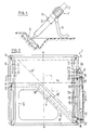
- Fig. 1 zeigt einen Werfer mit dem daran angebrachten Visier,
- Fig. 2 zeigt einen Axialschnitt durch das Visier nach Linie II/II in Fig. 3,
- Fig. 3 zeigt einen Radialschnitt durch das Visier nach Linie III/III in Fig. 2,und
- Fig. 4 ist eine Teil-Seitenansicht mit dem Fenster des Visiers.
- Das ringförmige Visier 1 ist drehbar auf einer Lafette 3 des Werfers angebracht. Die Lafette 3 mit zwei einklappbaren Beinen 4 ist normalerweise durch eine federbelastete Bremse am Rohr 2 festgestellt, kann jedoch bei Druck auf einen Auslöseknopf 5 längs des Rohres 2 verschoben werden, um die Elevation des Rohres zu verändern. Das Rohr ist auf eine Grundplatte 6 abgestützt.
- Das ringförmige Visier 1 ist in den Fig. 2 - 4 dargestellt. Es ist aus einem Innenring 7 und einem Aussenring 8 aufgebaut, welche mittels Dichtungsringen 9 und 10 dicht miteinander verbunden und durch einen Schwerspannstift 11 gegenseitig gesichert sind. Der Innenring 7 ist mit einer umlaufenden Nut 12 versehen, deren axiale Länge auf der einen Seite, in Fig. 2 links, geringer ist als auf der Gegenseite. Diese Nut bildet bei vereinigten Ringen 7 und 8 zwischen denselben einen durch die Dichtungen 9 und 10 abgedichteten Ringraum 13, welcher entsprechend der Nut 12 variable axiale Höhe aufweist. Der Boden dieses Ringraumes 13, welcher durch die untere Flanke 14 der Nut 12 gebildet ist, liegt auf der in Fig. 2 links dargestellten Hälfte des Visiers in einer Radialebene. In der anderen Hälfte des Visiers liegt der Boden 14ʹ des Ringraumes 13 in einer Ebene, die gegenüber der Achse A des Visiers um einen Winkel E geneigt ist, welcher der minimalen Elevation des Rohres 2 entspricht. Wenn also gemäss Fig. 1 diese minimale Elvation 45° beträgt, ist die Ebene des Bodens 14ʹ um 45° gegenüber der Achse A geneigt. Im Bereiche, in welchem sich kein Ringraum befindet, ist der Innenring 7 mit Aussparungen 16 versehen. Diese Massnahme dient der Einsparung von unnötigem Material und Gewicht.
- Auf der Seite des Bodenabschnitts 14ʹ weist der Aussenring 8 ein Auge 17 mit einer Fensteröffnung 18 auf, in welche ein durchsichtiges Fenster 19 eingesetzt ist. Dieses Fenster ist mittels Sicherungsbügeln 20 in der Fensteröffnung gesichert und mittels einer Dichtung 21 gegen den Ringraum 13 abgedichtet. Die Fensteröffnung weist oben und unten je eine Nut 22 auf, in welche eine biegsame und undurchsichtige Abdeckplatte 23 eingeschnappt werden kann. Innerhalb des Fensters 19 befindet sich ein flacher Leuchtkörper 24, welcher die im Ringraum 13 befindliche Flüssigkeit sowie das Fenster 19 durchleuchtet und das Niveau der Flüssigkeit bzw. einer Skala auf dem Fenster 19 in jedem Falle gut sichtbar macht. Die Abdeckplatte 23 dient nicht nur dem Schutz des Fensters 19 sondern verhindert auch den Austritt von Licht aus dem Leuchtkörper 24 beim Transport der Waffe in der Dunkelheit.
- Wie bereits erwähnt, ist in den Ringraum 13 eine geeignete Flüssigkeit geringer Viskosität eingefüllt. Sie erreicht bei der in Fig. 2 dargestellten Lage des Visiers, welche der senkrechten Stellung des Rohres 2 entspricht, das mit N bezeichnete Niveau. Bei dieser Stellung befindet sich auf dem Fenster 19 ein Skalenstrich, welcher der Eichung des Visiers dient. Da die vertikale Stellung niemals einer Feuerstellung entspricht, dient sie nur als Park- bzw. Eichstellung, in welcher das Flüssigkeitsniveau genau geregelt wird. Zu diesem Zwecke dient nötigenfalls eine Gewindebohrung 25 im Aussenring 8, welche normalerweise durch eine Schraube 26 mit Dichtungsring 27 verschlossen ist. Bei entfernter Schraube 26 kann beispielsweise mit einer Pipette Flüssigkeit in den Ringraum 13 nachgefüllt oder bei Ueberfüllung entnommen werden, um das genaue Niveau in der Eichstellung herzustellen. Bei dieser Stellung würde auch eine maximale Elevation angezeigt, die jedoch, wie erwähnt, keiner praktischen Feuerstellung entspricht. Bei dieser Stellung befindet sich im Bereiche des Bodenabschnitts 14 des Ringraumes 13 nur eine sehr dünne Flüssigkeitsschicht von beispielsweise etwa 2 mm Tiefe, während sich der Rest der Flüssigkeit über dem Bodenabschnitt 14ʹ befindet. Wird nun das Rohr in Richtung abnehmender Elevation geneigt, fliesst die Flüssigkeit über die zwischen den Bodenabschnitten 14 und 14ʹ gebildete Kante 14ʺ von rechts in Fig. 2 nach links, wobei der Flüssigkeitsspiegel selbstverständlich horizontal bleibt und infolgedessen im Bereiche des Fensters 13 bzw. der am Fenster angebrachten Skala absinkt. An dieser Skala kann dann die entsprechende Neigung bzw. Elevation abgelesen werden, und zwar entweder in Graden oder Artillerie-Promillen. Die Eichung kann jedoch auch direkt in der Schussdistanz für bestimmte Ladungen bzw. bestimmte Munitionsarten geeicht sein. Es ist auch möglich, nebeneinander zwei oder mehrere Skalen anzuordnen, welche verschiedene Grössen angeben. Es ist allerdings vorzuziehen, im Falle mehrerer Skalen entsprechend viele Fenster vorzusehen, in welchen je nur eine Skala erscheint und die jeweils nicht benützten Skalen durch Abdeckplatten 23 abgedeckt zu lassen, um Verwechslungen auszuschliessen. Wie in Fig. 4 angedeutet, sollte das im Fenster sichtbare Niveau N parallel zu den Skalenstrichen erscheinen, um die Elevation oder Schussdistanz korrekt ablesen zu können. Befindet sich jedoch das Visier nicht in der richtigen Drehlage auf dem Rohr, erscheint das Niveau N zu den Skalenstrichen geneigt, in welchem Falle das Visier gedreht werden muss, bis das Niveau parallel zu den Skalenstrichen steht.
- Bei minimaler Elevation steht der Abschnitt 14ʹ der Bodenfläche des Ringraumes 13 horizontal, in welchem Falle dann das Flüssigkeitsniveau gemäss dem in Fig. 2 strichpunktiert angedeuteten Niveau Nʹ steht. Es liegt nun eine Flüssigkeitsschicht sehr geringer Dicke auf dem Bodenbereich 14ʹ, während der Hauptanteil der Flüssigkeit sich im Bereiche 14 des Bodens befindet. Die Abknickung des Bodens etwa in einer Mittelsymmetrie-Ebene des Visiers hat die Wirkung eines Verdrängers, d.h., es wird soviel Flüssigkeit verdrängt wie irgend möglich, wobei jedoch die Bedingung eingehalten ist, dass in allen Fällen ein durchgehender, ebener Flüssigkeitsspiegel am ganzen Umfang des Ringraumes 13 besteht. Wie durch die Linie Nʹ angedeutet, besteht allerdings bei minimaler Elevation in dem in Fig. 2 oben links liegenden Bereiche des Ringraumes kein freier Flüssigkeitsspiegel mehr. Bei dieser Situation muss die Skala im unteren Bereiche d.h. bei minimalen Elevation etwas korrigiert werden. Es wäre jedoch durchaus möglich, die axiale Höhe des Ringraumes so zu wählen, dass stets am ganzen Umfang ein freier Flüssigkeitsspiegel besteht.
Claims (10)
Priority Applications (1)
| Application Number | Priority Date | Filing Date | Title |
|---|---|---|---|
| AT87810419T ATE56536T1 (de) | 1986-08-15 | 1987-07-27 | Visier an einer feuerwaffe. |
Applications Claiming Priority (2)
| Application Number | Priority Date | Filing Date | Title |
|---|---|---|---|
| CH3293/86 | 1986-08-15 | ||
| CH3293/86A CH671456A5 (de) | 1986-08-15 | 1986-08-15 |
Publications (2)
| Publication Number | Publication Date |
|---|---|
| EP0258176A1 true EP0258176A1 (de) | 1988-03-02 |
| EP0258176B1 EP0258176B1 (de) | 1990-09-12 |
Family
ID=4252847
Family Applications (1)
| Application Number | Title | Priority Date | Filing Date |
|---|---|---|---|
| EP87810419A Expired - Lifetime EP0258176B1 (de) | 1986-08-15 | 1987-07-27 | Visier an einer Feuerwaffe |
Country Status (6)
| Country | Link |
|---|---|
| US (1) | US4785543A (de) |
| EP (1) | EP0258176B1 (de) |
| AT (1) | ATE56536T1 (de) |
| CH (1) | CH671456A5 (de) |
| DE (1) | DE3764911D1 (de) |
| ES (1) | ES2017528B3 (de) |
Cited By (1)
| Publication number | Priority date | Publication date | Assignee | Title |
|---|---|---|---|---|
| WO2011057756A1 (de) * | 2009-11-16 | 2011-05-19 | Rheinmetall Waffe Munition Gmbh | Vorrichtung insbesondere zur ermittlung der neigung eines waffenrohres beim richten |
Citations (2)
| Publication number | Priority date | Publication date | Assignee | Title |
|---|---|---|---|---|
| CH637765A5 (fr) * | 1980-10-17 | 1983-08-15 | Valinor Sa | Dispositif pour reperer le degre d'inclinaison de l'axe d'un objet tubulaire. |
| EP0190549A1 (de) * | 1984-12-28 | 1986-08-13 | BÖHLER PNEUMATIK INTERNATIONAL GESELLSCHAFT m.b.H. | Geschosswaffe |
Family Cites Families (1)
| Publication number | Priority date | Publication date | Assignee | Title |
|---|---|---|---|---|
| JPS6111609A (ja) * | 1984-06-27 | 1986-01-20 | Toshiba Corp | 傾斜角検出計 |
-
1986
- 1986-08-15 CH CH3293/86A patent/CH671456A5/de not_active IP Right Cessation
-
1987
- 1987-07-27 ES ES87810419T patent/ES2017528B3/es not_active Expired - Lifetime
- 1987-07-27 EP EP87810419A patent/EP0258176B1/de not_active Expired - Lifetime
- 1987-07-27 DE DE8787810419T patent/DE3764911D1/de not_active Expired - Fee Related
- 1987-07-27 AT AT87810419T patent/ATE56536T1/de not_active IP Right Cessation
- 1987-07-28 US US07/078,635 patent/US4785543A/en not_active Expired - Fee Related
Patent Citations (2)
| Publication number | Priority date | Publication date | Assignee | Title |
|---|---|---|---|---|
| CH637765A5 (fr) * | 1980-10-17 | 1983-08-15 | Valinor Sa | Dispositif pour reperer le degre d'inclinaison de l'axe d'un objet tubulaire. |
| EP0190549A1 (de) * | 1984-12-28 | 1986-08-13 | BÖHLER PNEUMATIK INTERNATIONAL GESELLSCHAFT m.b.H. | Geschosswaffe |
Non-Patent Citations (1)
| Title |
|---|
| PATENT ABSTRACTS OF JAPAN, Band 10, Nr. 157 (P-464)[2213], 6. Juni 1986; & JP-A-61 11 609 (TOSHIBA K.K.) 20-01-1986 * |
Cited By (1)
| Publication number | Priority date | Publication date | Assignee | Title |
|---|---|---|---|---|
| WO2011057756A1 (de) * | 2009-11-16 | 2011-05-19 | Rheinmetall Waffe Munition Gmbh | Vorrichtung insbesondere zur ermittlung der neigung eines waffenrohres beim richten |
Also Published As
| Publication number | Publication date |
|---|---|
| CH671456A5 (de) | 1989-08-31 |
| EP0258176B1 (de) | 1990-09-12 |
| US4785543A (en) | 1988-11-22 |
| ES2017528B3 (es) | 1991-02-16 |
| DE3764911D1 (de) | 1990-10-18 |
| ATE56536T1 (de) | 1990-09-15 |
Similar Documents
| Publication | Publication Date | Title |
|---|---|---|
| DE1578271C3 (de) | Visiereinrichtung für Schußwaffen, Navigationsinstrumente und dergl | |
| DE3401855C2 (de) | ||
| DE102018133064A1 (de) | Ballistisches Zielsystem mit digitalem Verstellrad | |
| DE2736415A1 (de) | Ziel- und richtgeraet | |
| DE102017100720B4 (de) | Absehen und hiermit ausgestattetes Zielfernrohr, Schusswaffe hiermit und Verfahren zum Treffen eines Zielobjekts mit einem Projektil | |
| AT518877B1 (de) | Verstellelement zur Verstellung einer Visierlinie einer optischen Visiereinrichtung, sowie Zielfernrohr mit dem Verstellelement und Waffe mit dem Zielfernrohr, sowie Verfahren zur Verstellung der Visierlinie | |
| EP0258176B1 (de) | Visier an einer Feuerwaffe | |
| DE2459130A1 (de) | Messinstrument | |
| DE2513760C3 (de) | Einrichtung zum optischen Erfassen und Verfolgen eines Objektes | |
| DE10243411A1 (de) | Verfahren zur Kalibrierung von Messgeräten zur quantitativen Infrarotstrahlungsmessung | |
| DE538867C (de) | Libelle, Fokuslibelle o. dgl., mit Ausgleichsraum | |
| CH631008A5 (de) | Zielmarkenscheibe fuer visiereinrichtung. | |
| DE4102720A1 (de) | Visiereinrichtung mit neigungssensor | |
| DE2154087C3 (de) | Astronomisches Spiegelteleskop | |
| DE1448815B2 (de) | Gerät zur Anzeige einer Größe, die von einer zweiten Größe abhängt | |
| DE3824268C2 (de) | ||
| DE1578302C3 (de) | Zielvorrichtung für Schu Bwaffen | |
| AT47938B (de) | Mechanische Libelle. | |
| DE2138947B2 (de) | Steuer- und sicherheitsvorrichtung fuer eine in einer oeffnung angeordnete verschliessbare klappe | |
| DE2851527A1 (de) | Kugellafette | |
| DE3204817A1 (de) | Druckdichte durchfuehrung fuer mess-, regel- und steuergeraete o.dgl. | |
| DE102023135978A1 (de) | Geschütz und Verfahren zur Justierung einer Zielvorrichtung eines solchen Geschützes | |
| DE286909C (de) | ||
| DE3307655A1 (de) | Vibrationsgedaempftes zeigerthermometer mit bimetallantrieb | |
| DE1578302B2 (de) | Zielvorrichtung für Schußwaffen |
Legal Events
| Date | Code | Title | Description |
|---|---|---|---|
| PUAI | Public reference made under article 153(3) epc to a published international application that has entered the european phase |
Free format text: ORIGINAL CODE: 0009012 |
|
| AK | Designated contracting states |
Kind code of ref document: A1 Designated state(s): AT BE DE ES FR GB IT NL SE |
|
| 17P | Request for examination filed |
Effective date: 19880311 |
|
| 17Q | First examination report despatched |
Effective date: 19891116 |
|
| GRAA | (expected) grant |
Free format text: ORIGINAL CODE: 0009210 |
|
| AK | Designated contracting states |
Kind code of ref document: B1 Designated state(s): AT BE DE ES FR GB IT NL SE |
|
| REF | Corresponds to: |
Ref document number: 56536 Country of ref document: AT Date of ref document: 19900915 Kind code of ref document: T |
|
| ITF | It: translation for a ep patent filed | ||
| REF | Corresponds to: |
Ref document number: 3764911 Country of ref document: DE Date of ref document: 19901018 |
|
| GBT | Gb: translation of ep patent filed (gb section 77(6)(a)/1977) | ||
| ET | Fr: translation filed | ||
| PLBE | No opposition filed within time limit |
Free format text: ORIGINAL CODE: 0009261 |
|
| STAA | Information on the status of an ep patent application or granted ep patent |
Free format text: STATUS: NO OPPOSITION FILED WITHIN TIME LIMIT |
|
| ITTA | It: last paid annual fee | ||
| 26N | No opposition filed | ||
| EAL | Se: european patent in force in sweden |
Ref document number: 87810419.9 |
|
| PGFP | Annual fee paid to national office [announced via postgrant information from national office to epo] |
Ref country code: GB Payment date: 19970606 Year of fee payment: 11 |
|
| PGFP | Annual fee paid to national office [announced via postgrant information from national office to epo] |
Ref country code: SE Payment date: 19970610 Year of fee payment: 11 |
|
| PGFP | Annual fee paid to national office [announced via postgrant information from national office to epo] |
Ref country code: ES Payment date: 19970714 Year of fee payment: 11 |
|
| PGFP | Annual fee paid to national office [announced via postgrant information from national office to epo] |
Ref country code: FR Payment date: 19970729 Year of fee payment: 11 |
|
| PGFP | Annual fee paid to national office [announced via postgrant information from national office to epo] |
Ref country code: NL Payment date: 19970731 Year of fee payment: 11 Ref country code: AT Payment date: 19970731 Year of fee payment: 11 |
|
| PGFP | Annual fee paid to national office [announced via postgrant information from national office to epo] |
Ref country code: DE Payment date: 19970814 Year of fee payment: 11 |
|
| PGFP | Annual fee paid to national office [announced via postgrant information from national office to epo] |
Ref country code: BE Payment date: 19970828 Year of fee payment: 11 |
|
| PG25 | Lapsed in a contracting state [announced via postgrant information from national office to epo] |
Ref country code: GB Free format text: LAPSE BECAUSE OF NON-PAYMENT OF DUE FEES Effective date: 19980727 Ref country code: AT Free format text: LAPSE BECAUSE OF NON-PAYMENT OF DUE FEES Effective date: 19980727 |
|
| PG25 | Lapsed in a contracting state [announced via postgrant information from national office to epo] |
Ref country code: SE Free format text: LAPSE BECAUSE OF NON-PAYMENT OF DUE FEES Effective date: 19980728 Ref country code: ES Free format text: LAPSE BECAUSE OF THE APPLICANT RENOUNCES Effective date: 19980728 |
|
| PG25 | Lapsed in a contracting state [announced via postgrant information from national office to epo] |
Ref country code: BE Free format text: LAPSE BECAUSE OF NON-PAYMENT OF DUE FEES Effective date: 19980731 |
|
| BERE | Be: lapsed |
Owner name: SCHWEIZERISCHE EIDGENOSSENSCHAFT EIDG. WAFFENFABR Effective date: 19980731 |
|
| PG25 | Lapsed in a contracting state [announced via postgrant information from national office to epo] |
Ref country code: NL Free format text: LAPSE BECAUSE OF NON-PAYMENT OF DUE FEES Effective date: 19990201 |
|
| GBPC | Gb: european patent ceased through non-payment of renewal fee |
Effective date: 19980727 |
|
| EUG | Se: european patent has lapsed |
Ref document number: 87810419.9 |
|
| PG25 | Lapsed in a contracting state [announced via postgrant information from national office to epo] |
Ref country code: FR Free format text: LAPSE BECAUSE OF NON-PAYMENT OF DUE FEES Effective date: 19990331 |
|
| NLV4 | Nl: lapsed or anulled due to non-payment of the annual fee |
Effective date: 19990201 |
|
| PG25 | Lapsed in a contracting state [announced via postgrant information from national office to epo] |
Ref country code: DE Free format text: LAPSE BECAUSE OF NON-PAYMENT OF DUE FEES Effective date: 19990501 |
|
| REG | Reference to a national code |
Ref country code: FR Ref legal event code: ST |
|
| REG | Reference to a national code |
Ref country code: ES Ref legal event code: FD2A Effective date: 20001102 |
|
| PG25 | Lapsed in a contracting state [announced via postgrant information from national office to epo] |
Ref country code: IT Free format text: LAPSE BECAUSE OF NON-PAYMENT OF DUE FEES;WARNING: LAPSES OF ITALIAN PATENTS WITH EFFECTIVE DATE BEFORE 2007 MAY HAVE OCCURRED AT ANY TIME BEFORE 2007. THE CORRECT EFFECTIVE DATE MAY BE DIFFERENT FROM THE ONE RECORDED. Effective date: 20050727 |