EP0258205B1 - Elément de liaison pour les deux plaques d'un coffrage perdu - Google Patents
Elément de liaison pour les deux plaques d'un coffrage perdu Download PDFInfo
- Publication number
- EP0258205B1 EP0258205B1 EP19870890149 EP87890149A EP0258205B1 EP 0258205 B1 EP0258205 B1 EP 0258205B1 EP 19870890149 EP19870890149 EP 19870890149 EP 87890149 A EP87890149 A EP 87890149A EP 0258205 B1 EP0258205 B1 EP 0258205B1
- Authority
- EP
- European Patent Office
- Prior art keywords
- flanges
- undercut portions
- connecting member
- slots
- parts
- Prior art date
- Legal status (The legal status is an assumption and is not a legal conclusion. Google has not performed a legal analysis and makes no representation as to the accuracy of the status listed.)
- Expired - Lifetime
Links
Images


Classifications
-
- E—FIXED CONSTRUCTIONS
- E04—BUILDING
- E04B—GENERAL BUILDING CONSTRUCTIONS; WALLS, e.g. PARTITIONS; ROOFS; FLOORS; CEILINGS; INSULATION OR OTHER PROTECTION OF BUILDINGS
- E04B2/00—Walls, e.g. partitions, for buildings; Wall construction with regard to insulation; Connections specially adapted to walls
- E04B2/84—Walls made by casting, pouring, or tamping in situ
- E04B2/86—Walls made by casting, pouring, or tamping in situ made in permanent forms
- E04B2/8635—Walls made by casting, pouring, or tamping in situ made in permanent forms with ties attached to the inner faces of the forms
Definitions
- the invention relates to an at least two-part connector for holding together the finished wall or ceiling base plates of a lost formwork at a distance from each other for the production of reinforced concrete walls, sloping ceilings, etc., where appropriate, with two parts of the connector with foot parts each one of the base plates non-positively, e.g. by screwing, are connectable and at least one of the parts has undercuts into which the other part can be snapped.
- Connectors of this type are known and are widely used, e.g. the connecting piece in which, according to AT-PS 380 909, the plate-shaped feet have heads connected via a stem, web or the like, which are designed to be interlocking like a push button. If such connectors are made of plastic, it has proven to be expedient to effect the connection to the base plates by gluing, since adhesives according to the current standard have a sufficient adhesive force, which often exceeds the cohesive force of the material, for example a chipboard .
- a disadvantage here is the relatively long setting time of the adhesive, which is why the plates provided with the connecting pieces have to be temporarily stored in large storage rooms until they can be used.
- the part (s) having the undercut is / are U-shaped and consists of a base plate with two lateral webs which have the undercuts exists (exist), which extend perpendicular to the footplate, and that the part which can be snapped into these undercuts is provided with spreadable, provided with recesses, into which recesses the undercuts of the other part can be resiliently latched crosswise.
- the part B provided with recesses is approximately X-shaped, with two webs extending opposite and diverging, preferably from a common central web, which at one end have foot plates for fastening this part one of the base plates, on the other hand have recesses for engaging the undercuts of the other part A of the connecting piece.
- Part B (the part provided with recesses for engaging the undercuts of the other part of the connecting piece) can advantageously have additional recesses for inserting additional reinforcement.
- this is formed in three parts, etc. two symmetrically opposite, undercut parts A are provided, into which undercuts the recesses on the webs of a cross-sectionally X-shaped or H-shaped part can be snapped.
- the connector according to the invention makes it possible, as in the method mentioned at the beginning, described in AT-PS 380 909, to produce a lost formwork for a wall or sloping ceiling in two parts in order to store it easily, cut it to the desired format, transport it and only then to be able to merge at a later time.
- cutouts and openings can be provided for a sloping wall or ceiling, cables and additional reinforcements can be inserted, regardless of the actual setting process of the formwork on the construction site.
- FIGS. 1 and 2 show a first exemplary embodiment before and after the two parts have been joined together.
- 3 and 4 a second embodiment, also before and after assembly.
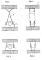
- 5 and 6 a connecting piece according to FIGS. 1 and 2 is shown in the state attached to two base plates.
- 7 and 8 show, analogously, the second exemplary embodiment according to FIGS. 3 and 4.
- FIGS. 9 and 10 or 11 and 12 illustrate a further connecting piece consisting of three parts, each in two views, also fastened to two base plates, that they distance and hold together.
- the connecting piece according to FIGS. 1 and 2 consists of a U-shaped part A and the like provided with undercuts 2. from a base plate 3 and two lateral webs 4 parallel to one another and having the undercuts 2.
- a part B provided with recesses 5 can be snapped into these undercuts 2, so that the state shown in FIG. 2 results.
- Part B is X-shaped in cross section, whereby I extend two webs 8 and 9 divergingly away from a central web 7.
- the webs 8 can be spread apart in order to make it possible for the webs 4 provided with undercuts to not snap into place crosswise.
- the webs 9 end in angled base plates 10, which have the bores required for screwing this part onto a base plate 11, as can be seen in FIGS. 5 and 6.
- the base plates 11 can be e.g. Provide parts A and B in the manufacturing plant, which are screwed on according to a grid.
- Such base plates which are therefore intended for the formation of a lost formwork for a wall or sloping ceiling, can be cut to the desired formats and possibly with lines, reinforcements, fittings and. Like. Be provided. Then they can be assembled and moved to a finished formwork already in the factory or on the construction site by plugging the two parts of all connecting pieces together, whereupon the formwork is filled with flow concrete.
- FIGS. 3 and 4 or 7 and 8 differs from that described so far only by a different embodiment of part B, which in this case has a U-shaped profile.
- a base plate 12 is provided with lateral webs 13 which have recesses 5. These recesses 5 serve to snap into the undercuts 2 of the respectively associated part A, as shown in FIG. 4.
- FIG. 9-12 show two three-part connecting pieces according to the invention, wherein on the base plates 11, opposite each other symmetrically, a part A provided with undercuts 2 is screwed.
- the recesses 5 on the webs 14 engage either a cross-sectionally H-shaped (FIGS. 9, 10) or a cross-sectionally X-shaped profile (FIGS. 11, 12), the latter being provided with a central web 15 can be, from which the webs 14 extend divergingly.
- the parts B of the connecting piece according to the invention can be provided with additional recesses 16 for the insertion of reinforcements.
Landscapes
- Engineering & Computer Science (AREA)
- Architecture (AREA)
- Physics & Mathematics (AREA)
- Electromagnetism (AREA)
- Civil Engineering (AREA)
- Structural Engineering (AREA)
- Forms Removed On Construction Sites Or Auxiliary Members Thereof (AREA)
Claims (4)
Applications Claiming Priority (2)
| Application Number | Priority Date | Filing Date | Title |
|---|---|---|---|
| AT1802/86 | 1986-07-03 | ||
| AT180286A AT385806B (de) | 1986-07-03 | 1986-07-03 | Mindestens zweiteiliges verbindungsstueck zum zusammenhalten von zwei die fertige wand- bzw. deckenflaeche aufweisenden grundplatten |
Publications (2)
| Publication Number | Publication Date |
|---|---|
| EP0258205A1 EP0258205A1 (fr) | 1988-03-02 |
| EP0258205B1 true EP0258205B1 (fr) | 1990-12-19 |
Family
ID=3521286
Family Applications (1)
| Application Number | Title | Priority Date | Filing Date |
|---|---|---|---|
| EP19870890149 Expired - Lifetime EP0258205B1 (fr) | 1986-07-03 | 1987-07-02 | Elément de liaison pour les deux plaques d'un coffrage perdu |
Country Status (3)
| Country | Link |
|---|---|
| EP (1) | EP0258205B1 (fr) |
| AT (1) | AT385806B (fr) |
| DE (1) | DE3766778D1 (fr) |
Cited By (4)
| Publication number | Priority date | Publication date | Assignee | Title |
|---|---|---|---|---|
| EP0537727A1 (fr) * | 1991-10-18 | 1993-04-21 | Kunz GmbH & Co. | Dispositif d'assemblage pour panneaux et/ou armatures en fer d'un coffrage composite |
| DE4134439A1 (de) * | 1991-10-18 | 1993-04-22 | Kunz Gmbh & Co | Verbindungseinrichtung fuer zwei mit abstand zueinander angeordnete platten einer verbundschalung |
| USD377143S (en) | 1995-06-28 | 1997-01-07 | Kunz Gmbh & Co. | Joining spacer |
| EP0811731A1 (fr) * | 1996-06-03 | 1997-12-10 | Eva Maria Dipl.-Ing. Gruber | Structure et élément de plafond |
Families Citing this family (14)
| Publication number | Priority date | Publication date | Assignee | Title |
|---|---|---|---|---|
| DE9212596U1 (de) * | 1992-09-18 | 1992-11-26 | Metallwarenfabrik König GmbH, 7560 Gaggenau | Verbindungsstück zum Zusammenhalten von zwei Grundplatten einer verlorenen Schalung |
| DE4236958A1 (de) * | 1992-11-02 | 1994-08-18 | Weber Haus Gmbh & Co Kg | Verbindungsstück und eine verlorene Schalung |
| DE9214930U1 (de) * | 1992-11-03 | 1993-03-25 | Weber Haus GmbH & Co. KG., 7597 Rheinau | Verbindungsstück und eine verlorene Schalung |
| DE4327115A1 (de) * | 1993-08-12 | 1995-02-16 | Continua Kunststoffverarbeitun | Abstandshalter für Plattenelemente eines Wand-/Deckensystems |
| DE4341856C2 (de) * | 1993-12-08 | 2001-05-31 | Schwoerer Haus Kg | Verbundschalung |
| DE29502890U1 (de) * | 1995-02-24 | 1996-06-27 | Josef König Metallwarenfabrik GmbH, 76571 Gaggenau | Verbindungsteil zum Zusammenhalten von zwei Grundplatten einer verlorenen Schalung |
| FR2740488B1 (fr) * | 1995-10-27 | 1997-12-26 | Stradal Sa | Procede de fabrication de blocs de parement |
| DE19637379C2 (de) * | 1996-09-13 | 1999-06-10 | Buck Chem Tech Werke | Verfahren zum Herstellen von doppelwandigen Wandelementen, dazu verwendete Anlage sowie danach hergestelltes Wandelemente |
| DE29617776U1 (de) * | 1996-10-12 | 1996-11-28 | KEWO MARKENHAUS GmbH, 53937 Schleiden | Verbindungsvorrichtung für die Schalungsplatten einer verlorenen Betonschalung |
| DE29713879U1 (de) | 1997-08-05 | 1997-10-02 | Nemis Establishment, Vaduz | Abstandhalter |
| DE19742539A1 (de) * | 1997-09-26 | 1999-04-01 | Neubauer Miciuk Dorota | Schalungselement für die Herstellung von Massivwänden |
| DE102005028697B4 (de) * | 2004-12-31 | 2007-06-28 | Fritz, Bruno O., Dipl.-Ing. (FH) | System zum Erstellen einer Gebäudewand |
| EP2333183A1 (fr) * | 2009-11-27 | 2011-06-15 | McGovern, James | Dispositif de connecteur pour panneaux d'un coffrage perdu |
| FR3004473B1 (fr) * | 2013-04-11 | 2017-11-24 | H&H Tech | Poutrelle de mur isolant a coffrage integre |
Family Cites Families (2)
| Publication number | Priority date | Publication date | Assignee | Title |
|---|---|---|---|---|
| EP0164330B1 (fr) * | 1984-04-06 | 1990-10-03 | Eva Maria Dipl.-Ing. Gruber | Plancher en béton armé |
| AT380909B (de) * | 1984-10-19 | 1986-07-25 | Fuechtner Eva Maria Dipl Ing | Zweiteiliges verbindungsstueck zur herstellung von zwei die fertige wand - bzw. deckenoberflaeche aufweisender grundplatten einer verlorenen schalung |
-
1986
- 1986-07-03 AT AT180286A patent/AT385806B/de not_active IP Right Cessation
-
1987
- 1987-07-02 DE DE8787890149T patent/DE3766778D1/de not_active Expired - Lifetime
- 1987-07-02 EP EP19870890149 patent/EP0258205B1/fr not_active Expired - Lifetime
Cited By (5)
| Publication number | Priority date | Publication date | Assignee | Title |
|---|---|---|---|---|
| EP0537727A1 (fr) * | 1991-10-18 | 1993-04-21 | Kunz GmbH & Co. | Dispositif d'assemblage pour panneaux et/ou armatures en fer d'un coffrage composite |
| DE4134439A1 (de) * | 1991-10-18 | 1993-04-22 | Kunz Gmbh & Co | Verbindungseinrichtung fuer zwei mit abstand zueinander angeordnete platten einer verbundschalung |
| USD377143S (en) | 1995-06-28 | 1997-01-07 | Kunz Gmbh & Co. | Joining spacer |
| EP0811731A1 (fr) * | 1996-06-03 | 1997-12-10 | Eva Maria Dipl.-Ing. Gruber | Structure et élément de plafond |
| US5878541A (en) * | 1996-06-03 | 1999-03-09 | Gruber; Eva | Ceiling construction and ceiling panel |
Also Published As
| Publication number | Publication date |
|---|---|
| ATA180286A (de) | 1987-10-15 |
| DE3766778D1 (de) | 1991-01-31 |
| AT385806B (de) | 1988-05-25 |
| EP0258205A1 (fr) | 1988-03-02 |
Similar Documents
| Publication | Publication Date | Title |
|---|---|---|
| EP0258205B1 (fr) | Elément de liaison pour les deux plaques d'un coffrage perdu | |
| EP0179046A2 (fr) | Entretoise d'espacement pour la tenue des deux panneaux de base d'un coffrage perdu qui présentent la surface finie extérieure du mur ou du plafond | |
| DE2502992A1 (de) | Bodenplatte | |
| EP1223265A2 (fr) | Panneau de parquet | |
| WO2003009138A2 (fr) | Bride de fixation servant a l'assemblage d'elements de construction en bois | |
| DE4226742A1 (de) | Verkleidungselement für Böden, Decken, Wände und Fassaden | |
| DE2727286A1 (de) | Verfahren und vorrichtung zum verbinden flaechenfoermiger bauelemente | |
| DE203904T1 (de) | Schalungs- und bewehrungswand. | |
| EP0026803A1 (fr) | Dispositif de coffrage avec une plaque en faux-oeuvre et des armatures en attente | |
| EP3929376A1 (fr) | Système de profilé de joint de dilatation | |
| EP0153426B1 (fr) | Rayonnage à assemblages d'angle emboîtables | |
| DE2047632A1 (de) | Deckensteine aus aufgeschäumtem Poly styrol od dgl | |
| EP0299226A2 (fr) | Coffrage pour la réalisation d'éléments de construction en béton | |
| WO2004072405A1 (fr) | Sol | |
| EP1637669A2 (fr) | Bande de joint de dilatation | |
| DE2407877C3 (de) | Bandförmiges lichtdurchlässiges Bauelement aus einem Flansch und beidseitigen Stegen für die Montage und die Vorfertigung von lichtdurchlässigen Flächen | |
| DE3922711A1 (de) | Einrichtung zur festlegung zumindest eines bewehrungsstabes | |
| DE1292355B (de) | Verbindung von an einem beidseitig abstehenden Flansch eines Traegers anliegenden und dort gestossenen Decken- oder Wandplatten mit dem Traeger | |
| DE2607461C3 (de) | Versteifungsleiste für Deckenplatten | |
| CH686894A5 (de) | Verfahren zum Herstellen einer Dilatationsfuege zwischen zwei aneinanderstossenden Betonteilen. | |
| DE19744340A1 (de) | Modulares Verkleidungssystem | |
| DE909036C (de) | Einrichtung zur Verbindung von Bauplatten od. dgl. | |
| DE102018008870A1 (de) | Ankerschiene | |
| DE2804637A1 (de) | Vorgefertigtes bauteil zur verwendung im bauwesen | |
| CH703431A2 (de) | Baukonstruktionselement und entsprechendes Herstellungsverfahren für dieses. |
Legal Events
| Date | Code | Title | Description |
|---|---|---|---|
| PUAI | Public reference made under article 153(3) epc to a published international application that has entered the european phase |
Free format text: ORIGINAL CODE: 0009012 |
|
| AK | Designated contracting states |
Kind code of ref document: A1 Designated state(s): BE CH DE FR GB IT LI NL SE |
|
| 17P | Request for examination filed |
Effective date: 19880823 |
|
| 17Q | First examination report despatched |
Effective date: 19890519 |
|
| GRAA | (expected) grant |
Free format text: ORIGINAL CODE: 0009210 |
|
| AK | Designated contracting states |
Kind code of ref document: B1 Designated state(s): BE CH DE FR GB IT LI NL SE |
|
| REF | Corresponds to: |
Ref document number: 3766778 Country of ref document: DE Date of ref document: 19910131 |
|
| ITF | It: translation for a ep patent filed | ||
| ET | Fr: translation filed | ||
| GBT | Gb: translation of ep patent filed (gb section 77(6)(a)/1977) | ||
| ITTA | It: last paid annual fee | ||
| PLBE | No opposition filed within time limit |
Free format text: ORIGINAL CODE: 0009261 |
|
| STAA | Information on the status of an ep patent application or granted ep patent |
Free format text: STATUS: NO OPPOSITION FILED WITHIN TIME LIMIT |
|
| 26N | No opposition filed | ||
| EAL | Se: european patent in force in sweden |
Ref document number: 87890149.5 |
|
| PGFP | Annual fee paid to national office [announced via postgrant information from national office to epo] |
Ref country code: GB Payment date: 19970627 Year of fee payment: 11 |
|
| PGFP | Annual fee paid to national office [announced via postgrant information from national office to epo] |
Ref country code: BE Payment date: 19970718 Year of fee payment: 11 |
|
| PGFP | Annual fee paid to national office [announced via postgrant information from national office to epo] |
Ref country code: NL Payment date: 19970730 Year of fee payment: 11 |
|
| PG25 | Lapsed in a contracting state [announced via postgrant information from national office to epo] |
Ref country code: GB Free format text: LAPSE BECAUSE OF NON-PAYMENT OF DUE FEES Effective date: 19980702 |
|
| PGFP | Annual fee paid to national office [announced via postgrant information from national office to epo] |
Ref country code: CH Payment date: 19980706 Year of fee payment: 12 |
|
| PGFP | Annual fee paid to national office [announced via postgrant information from national office to epo] |
Ref country code: SE Payment date: 19980716 Year of fee payment: 12 |
|
| PG25 | Lapsed in a contracting state [announced via postgrant information from national office to epo] |
Ref country code: BE Free format text: LAPSE BECAUSE OF NON-PAYMENT OF DUE FEES Effective date: 19980731 |
|
| BERE | Be: lapsed |
Owner name: GRUBER EVA MARIA Effective date: 19980731 |
|
| PG25 | Lapsed in a contracting state [announced via postgrant information from national office to epo] |
Ref country code: NL Free format text: LAPSE BECAUSE OF NON-PAYMENT OF DUE FEES Effective date: 19990201 |
|
| GBPC | Gb: european patent ceased through non-payment of renewal fee |
Effective date: 19980702 |
|
| NLV4 | Nl: lapsed or anulled due to non-payment of the annual fee |
Effective date: 19990201 |
|
| PGFP | Annual fee paid to national office [announced via postgrant information from national office to epo] |
Ref country code: FR Payment date: 19990630 Year of fee payment: 13 |
|
| PG25 | Lapsed in a contracting state [announced via postgrant information from national office to epo] |
Ref country code: SE Free format text: THE PATENT HAS BEEN ANNULLED BY A DECISION OF A NATIONAL AUTHORITY Effective date: 19990703 |
|
| PG25 | Lapsed in a contracting state [announced via postgrant information from national office to epo] |
Ref country code: LI Free format text: LAPSE BECAUSE OF NON-PAYMENT OF DUE FEES Effective date: 19990731 Ref country code: CH Free format text: LAPSE BECAUSE OF NON-PAYMENT OF DUE FEES Effective date: 19990731 |
|
| PGFP | Annual fee paid to national office [announced via postgrant information from national office to epo] |
Ref country code: DE Payment date: 19990930 Year of fee payment: 13 |
|
| REG | Reference to a national code |
Ref country code: CH Ref legal event code: PL |
|
| EUG | Se: european patent has lapsed |
Ref document number: 87890149.5 |
|
| PG25 | Lapsed in a contracting state [announced via postgrant information from national office to epo] |
Ref country code: FR Free format text: LAPSE BECAUSE OF NON-PAYMENT OF DUE FEES Effective date: 20010330 |
|
| REG | Reference to a national code |
Ref country code: FR Ref legal event code: ST |
|
| PG25 | Lapsed in a contracting state [announced via postgrant information from national office to epo] |
Ref country code: DE Free format text: LAPSE BECAUSE OF NON-PAYMENT OF DUE FEES Effective date: 20010501 |
|
| PG25 | Lapsed in a contracting state [announced via postgrant information from national office to epo] |
Ref country code: IT Free format text: LAPSE BECAUSE OF NON-PAYMENT OF DUE FEES;WARNING: LAPSES OF ITALIAN PATENTS WITH EFFECTIVE DATE BEFORE 2007 MAY HAVE OCCURRED AT ANY TIME BEFORE 2007. THE CORRECT EFFECTIVE DATE MAY BE DIFFERENT FROM THE ONE RECORDED. Effective date: 20050702 |