EP0258209A2 - Dispositif pour le poinçonnage de tôles - Google Patents
Dispositif pour le poinçonnage de tôles Download PDFInfo
- Publication number
- EP0258209A2 EP0258209A2 EP87890186A EP87890186A EP0258209A2 EP 0258209 A2 EP0258209 A2 EP 0258209A2 EP 87890186 A EP87890186 A EP 87890186A EP 87890186 A EP87890186 A EP 87890186A EP 0258209 A2 EP0258209 A2 EP 0258209A2
- Authority
- EP
- European Patent Office
- Prior art keywords
- collets
- cross slide
- workpiece
- punching
- adjustable
- Prior art date
- Legal status (The legal status is an assumption and is not a legal conclusion. Google has not performed a legal analysis and makes no representation as to the accuracy of the status listed.)
- Withdrawn
Links
- 238000004080 punching Methods 0.000 title claims abstract description 52
- 239000002184 metal Substances 0.000 title claims abstract description 11
- 238000003754 machining Methods 0.000 description 3
- 238000010276 construction Methods 0.000 description 2
- 230000006978 adaptation Effects 0.000 description 1
- 230000007547 defect Effects 0.000 description 1
- 238000001514 detection method Methods 0.000 description 1
- 230000001771 impaired effect Effects 0.000 description 1
- 238000003780 insertion Methods 0.000 description 1
- 230000037431 insertion Effects 0.000 description 1
- 238000000034 method Methods 0.000 description 1
Images


Classifications
-
- B—PERFORMING OPERATIONS; TRANSPORTING
- B21—MECHANICAL METAL-WORKING WITHOUT ESSENTIALLY REMOVING MATERIAL; PUNCHING METAL
- B21D—WORKING OR PROCESSING OF SHEET METAL OR METAL TUBES, RODS OR PROFILES WITHOUT ESSENTIALLY REMOVING MATERIAL; PUNCHING METAL
- B21D28/00—Shaping by press-cutting; Perforating
- B21D28/24—Perforating, i.e. punching holes
- B21D28/26—Perforating, i.e. punching holes in sheets or flat parts
- B21D28/265—Perforating, i.e. punching holes in sheets or flat parts with relative movement of sheet and tools enabling the punching of holes in predetermined locations of the sheet, e.g. holes punching with template
-
- B—PERFORMING OPERATIONS; TRANSPORTING
- B21—MECHANICAL METAL-WORKING WITHOUT ESSENTIALLY REMOVING MATERIAL; PUNCHING METAL
- B21D—WORKING OR PROCESSING OF SHEET METAL OR METAL TUBES, RODS OR PROFILES WITHOUT ESSENTIALLY REMOVING MATERIAL; PUNCHING METAL
- B21D43/00—Feeding, positioning or storing devices combined with, or arranged in, or specially adapted for use in connection with, apparatus for working or processing sheet metal, metal tubes or metal profiles; Associations therewith of cutting devices
- B21D43/003—Positioning devices
-
- B—PERFORMING OPERATIONS; TRANSPORTING
- B21—MECHANICAL METAL-WORKING WITHOUT ESSENTIALLY REMOVING MATERIAL; PUNCHING METAL
- B21D—WORKING OR PROCESSING OF SHEET METAL OR METAL TUBES, RODS OR PROFILES WITHOUT ESSENTIALLY REMOVING MATERIAL; PUNCHING METAL
- B21D43/00—Feeding, positioning or storing devices combined with, or arranged in, or specially adapted for use in connection with, apparatus for working or processing sheet metal, metal tubes or metal profiles; Associations therewith of cutting devices
- B21D43/02—Advancing work in relation to the stroke of the die or tool
- B21D43/04—Advancing work in relation to the stroke of the die or tool by means in mechanical engagement with the work
- B21D43/10—Advancing work in relation to the stroke of the die or tool by means in mechanical engagement with the work by grippers
Definitions
- the invention relates to a device for punching sheet metal with a frame which carries a punching head, in particular with rows of individually operable punching tools, and a cross slide consisting of a cross slide and a longitudinal slide with collets for the workpiece guide.
- a rotary table must be provided for the workpieces if each of the tools arranged in rows in the punching head is to be used without restriction at any point on the workpiece, because the collets of the cross slide grasp the workpiece along an edge parallel to the tool rows and therefore this edge area of the workpiece is not freely accessible, so that the workpiece has to be rotated by 180 ° about an axis perpendicular to the workpiece plane in order to subsequently be able to punch the edge area gripped by the collets xunach.
- Rotating the workpiece through 180 ° requires, however, a corresponding design effort for the turning device and reclamping of the workpiece, which not only requires idle times for reclamping, turning and repositioning the workpiece, but also entails the risk of losing the exact workpiece alignment . Although this fact is particularly noticeable in row punching machines, these conditions also occur in punching machines with turret heads, because the turret head also takes up corresponding space.
- the invention is therefore based on the object of avoiding these defects and a device for punching sheet metal to improve the type described at the beginning with simple means so that the unlimited use of all tools of the punching head is ensured without having to reclamp and rotate the workpiece.
- the invention achieves the stated object in that at least two collets are adjustably mounted in the cross slide at least between two working positions, which have a distance from one another which is at least equal to the width of the punching head and measured transversely to the rows of tools.
- the adjustable arrangement of two collets makes it possible to grasp the workpieces through each collet either in the area of an edge parallel to the tool rows of the punching head or in the area of an edge perpendicular to it, the edge area of the workpiece facing the collets for punching with a any tool of the punching head is freely accessible. Because of the mutual distance between the working positions of the collets, the workpiece can be laterally encompassed by at least one collet at a distance corresponding to the punch head width from the workpiece edge facing the collets, so that the accessibility of the corner region of the workpiece facing this collet cannot be impaired by the collet .
- Whether the other collet is used in the front or rear working position depends on the one hand on the distance between the two collets and on the other hand on the size of the workpiece. If the length of the workpiece measured in the direction of the tool rows of the punching head exceeds the distance between the collets in this direction, then the workpiece can only be surrounded laterally by one collet, while the other collet grips the workpiece in the area of its edge parallel to the tool rows of the punching head.
- the adjustable collets can have three working positions with a mutual distance transversely to the tool rows of at least the punch head width and in the working position facing the cross slide can be in alignment with the possibly available non-adjustable collets of the cross slide.
- the workpiece In the working position of the adjustable collets aligned with the non-adjustable collets, the workpiece can be machined in a conventional manner in the edge area opposite the collets, even if construction parts of the cross slide in the area of the punching head protrude the collets against the punching head.
- the collets For the adjustment movement of the collets, these can be mounted in the cross slide so as to be displaceable transversely to the tool rows of the punching head.
- Particularly simple constructional relationships result, however, if the adjustable collets are provided on rotatably mounted arms.
- the arrangement of the collets on rotatable arms not only facilitates the adjustable mounting of the collets, but also ensures an independent alignment of the collet jaw with respect to the workpiece edge to be detected, so that with regard to the insertion opening of the collet jaw the fact can be disregarded that the workpiece alternately on each other vertical edges must be detected.
- these arms can each have a toothed segment which meshes with a driven rack.
- This rack can be slidably mounted on the cross slide parallel to the tool rows of the punching head in a space-saving manner and requires only a small adjustment path for the required swivel angle.
- the individual working positions of the adjustable collets can be determined by stops.
- the stop for the middle working position should be able to be adjusted between a stop position and a rest position so as not to impede the adjustment movement of the collets.
- the adjustable collets parallel to the rows of tools on the punching head Arrange cross slide so that the travel of the cross slide in this direction can be kept comparatively small even with larger workpiece dimensions.
- the otherwise required travel for the cross slide can be shortened by the adjustment length of the collets in the direction of this travel, which is particularly important when the workpiece has to be reclamped due to its dimensions, the adjustable collets being offset relative to the workpiece.
- an adjustment possibility of the collets parallel to the tool rows of the punching head makes it easy to adjust the distance of the collets from one another to the workpiece dimensions.
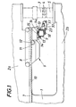
- the illustrated device for punching sheet metal consists essentially of a frame 1 which has an upper one Boom 2a, which carries a punching head 3 with row-arranged, individually operable and advantageously exchangeable punching tools 4, and has a lower boom 2b with a block 5 for the counter tools, and a cross slide 6 for the workpiece guide.
- This cross slide 6 is formed by a cross slide 8 movable on rails 7 of the frame 1 and a longitudinal slide 9 adjustable in the cross slide 8.
- the cross slide 8 is adjusted via a pinion 11 meshing with a toothed rack 10, which is mounted in the cross slide and can be driven by a motor 12.
- the longitudinal slide 9 is supported on rollers 13 mounted in the cross slide 8 and is laterally guided by inclined guide rollers 14.
- the longitudinal slide 9 is provided with at least two collets 17 which can be displaced transversely to the tool rows of the punching head 3 and by means of which the workpiece to be punched can be positioned and clamped relative to the respective punching tool 4 of the punching head 3 by a corresponding movement of the cross slide 6.
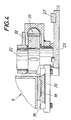
- the two collets 17 are slidably mounted on a longitudinal beam 18 of the longitudinal slide 9.
- the longitudinal member 18 engages in an undercut, preferably dovetail-shaped groove 19 of a support body 20 for the collets 17, which can be acted upon with the aid of an adjusting cylinder 21 clamped on the longitudinal member 18.
- a shaft 22 is rotatably mounted, on which an arm 23 is attached. This arm carries the collet 17, so that the collet 17 can be pivoted between the arm 23 and the shaft 22 between three working positions. These working positions are determined by stops 24, 25 and 26, which with a counter stop 27 on Arm 23 interact.
- this stop 25 is provided on a piston 28 which is pressed into its stop position by means of a spring 29 and via a Pressure medium line 30 can be acted against the force of the spring 29 in order to allow the counter-stop 27 of the arm 23 to pivot past in the drawn rest position (FIG. 3).
- the arrangement of the stops 24, 25 and 26 is such that the distances measured transversely to the longitudinal slide 9 or transversely to the tool rows of the punching head 3 between the successive working positions of the collets 17 correspond at least to the width of the punching head 3.
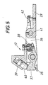
- a rack 31 is slidably mounted in the support body 20, which meshes with a toothed segment 32 on the shaft 22.
- This toothed rack 31 can be adjusted by two cylinders 33 which can be acted upon in opposite directions and are supported on the supporting body 20.
- the rack 31 is connected to the piston 34 of this cylinder 33.
- the collets 17 consist of a fixed clamping jaw 35 and a clamping jaw 37 pivotably mounted in the collet housing 36, which can be loaded against the force of a rubber spring 38 via a clamping cylinder 39 in the clamping direction.
- the piston 40 of the clamping cylinder 39 acts directly on the movable clamping jaw 37 via a cambered pressure surface.
- the housing 36 is pivotally mounted with respect to the arm 23 about an axis 41 with limited stops.
- the stop for the swivel angle is formed by a stop screw 42.
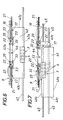
- the sheet 43 in the area of its edge 43b is displaceable by the adjustable collets 17 and one with the longitudinal slide 9 connected collet 44 is detected, which is in alignment with the collets in the rear working position, as indicated in Fig. 6.
- the workpiece 43 can therefore be positioned relative to the punching head 3 in any manner via the cross slide 6. Such free positioning is however not possible when machining the edge 43b of the workpiece 43 facing the longitudinal slide 9 while maintaining the workpiece clamping.
- the two adjustable collets 17 are pivoted together into the middle working position or into the front working position, or whether the workpiece is gripped by a collet in the middle and the other collet in the front working position, depends above all on the size of the metal sheet 43 to be processed from. If the metal sheet 43 can be encompassed on both sides by the two collets 17 in the front working position on the lateral edges 43c, the edge 43b remains over its entire length Length freely accessible. If the length of the edge 43b exceeds the distance between the collets 17 measured in this direction, the workpiece 43 must be grasped with a collet 17 in the area of the edge 43b and with the other collet 17 in the area of the edge 43c, as shown in full lines is shown in Fig. 7.
- the possible adjustment of the support body 20 along the longitudinal beam 18 of the longitudinal slide 9 with the aid of the actuating cylinders 21 not only allows the respective distance between the collets 17 to be adapted to the longitudinal extent of the metal sheets 43, but also enables the otherwise necessary travel of the longitudinal slide 9 to be shortened. because the travel of the longitudinal slide 9 can be shortened by the stroke of the cylinder 21.
- liftable holding strips 45 can be provided in the frame 1 of the punching device, these holding strips preferably being provided with holding magnets.
Landscapes
- Engineering & Computer Science (AREA)
- Mechanical Engineering (AREA)
- Punching Or Piercing (AREA)
- Perforating, Stamping-Out Or Severing By Means Other Than Cutting (AREA)
Applications Claiming Priority (2)
| Application Number | Priority Date | Filing Date | Title |
|---|---|---|---|
| AT2309/86 | 1986-08-27 | ||
| AT230986A AT384761B (de) | 1986-08-27 | 1986-08-27 | Vorrichtung zum stanzen von blechen |
Publications (2)
| Publication Number | Publication Date |
|---|---|
| EP0258209A2 true EP0258209A2 (fr) | 1988-03-02 |
| EP0258209A3 EP0258209A3 (fr) | 1989-04-12 |
Family
ID=3531965
Family Applications (1)
| Application Number | Title | Priority Date | Filing Date |
|---|---|---|---|
| EP87890186A Withdrawn EP0258209A3 (fr) | 1986-08-27 | 1987-08-11 | Dispositif pour le poinçonnage de tôles |
Country Status (3)
| Country | Link |
|---|---|
| EP (1) | EP0258209A3 (fr) |
| JP (1) | JPS63252622A (fr) |
| AT (1) | AT384761B (fr) |
Cited By (3)
| Publication number | Priority date | Publication date | Assignee | Title |
|---|---|---|---|---|
| IT202200010175A1 (it) * | 2022-05-17 | 2023-11-17 | Gem Srl | Testa di presa di una lamiera metallica piegata di una macchina punzonatrice automatica |
| CN118002679A (zh) * | 2024-04-08 | 2024-05-10 | 泰州市凯仕德机械设备有限公司 | 基于夹持自定位的工件冲孔用冲压装置 |
| CN120079758A (zh) * | 2025-04-30 | 2025-06-03 | 常州凯旺金属材料有限公司 | 一种设有压料结构的不锈钢线材校直冲压设备 |
Families Citing this family (3)
| Publication number | Priority date | Publication date | Assignee | Title |
|---|---|---|---|---|
| KR100700176B1 (ko) | 2002-12-18 | 2007-03-27 | 엘지.필립스 엘시디 주식회사 | 액정 표시패널의 디스펜서 및 이를 이용한 노즐과 기판의갭 제어방법 |
| CN114289616A (zh) * | 2021-12-14 | 2022-04-08 | 常熟市绿一电器配件制造有限公司 | 一种灭弧栅一次冲压成型模具 |
| CN117175870B (zh) * | 2023-11-01 | 2023-12-29 | 佛山登奇伺服科技有限公司 | 一种电机定转子冲片生产的定心装置 |
Family Cites Families (3)
| Publication number | Priority date | Publication date | Assignee | Title |
|---|---|---|---|---|
| US2934194A (en) * | 1959-01-13 | 1960-04-26 | Bliss E W Co | Work feed console |
| GB2130953B (en) * | 1982-11-02 | 1986-02-19 | Amada Co Ltd | Punch press |
| JPS60111729A (ja) * | 1983-11-21 | 1985-06-18 | Murata Mach Ltd | ワ−クホルダ装置 |
-
1986
- 1986-08-27 AT AT230986A patent/AT384761B/de not_active IP Right Cessation
-
1987
- 1987-08-11 EP EP87890186A patent/EP0258209A3/fr not_active Withdrawn
- 1987-08-27 JP JP21152587A patent/JPS63252622A/ja active Pending
Cited By (4)
| Publication number | Priority date | Publication date | Assignee | Title |
|---|---|---|---|---|
| IT202200010175A1 (it) * | 2022-05-17 | 2023-11-17 | Gem Srl | Testa di presa di una lamiera metallica piegata di una macchina punzonatrice automatica |
| CN118002679A (zh) * | 2024-04-08 | 2024-05-10 | 泰州市凯仕德机械设备有限公司 | 基于夹持自定位的工件冲孔用冲压装置 |
| CN118002679B (zh) * | 2024-04-08 | 2024-06-04 | 泰州市凯仕德机械设备有限公司 | 基于夹持自定位的工件冲孔用冲压装置 |
| CN120079758A (zh) * | 2025-04-30 | 2025-06-03 | 常州凯旺金属材料有限公司 | 一种设有压料结构的不锈钢线材校直冲压设备 |
Also Published As
| Publication number | Publication date |
|---|---|
| ATA230986A (de) | 1987-06-15 |
| JPS63252622A (ja) | 1988-10-19 |
| AT384761B (de) | 1988-01-11 |
| EP0258209A3 (fr) | 1989-04-12 |
Similar Documents
| Publication | Publication Date | Title |
|---|---|---|
| EP0242519B2 (fr) | Scie sauteuse | |
| DE2760355C2 (fr) | ||
| WO1997046339A1 (fr) | Machine d'usinage pour pieces sous forme de plaques, notamment pour produire des bords plies sur des pieces en tole | |
| EP0330970A2 (fr) | Dispositif pour le positionnement d'éléments de cadre courbes et pour le fraisage de rainures trapézoidales dans ces éléments de cadre | |
| EP0258209A2 (fr) | Dispositif pour le poinçonnage de tôles | |
| DE3941551A1 (de) | Vorrichtung zum positionieren von plattenfoermigen werkstuecken | |
| DE3320283A1 (de) | Verfahren zum schneiden und vorrichtung zum steuern des saegebandvorschubes bei bandsaegemaschinen | |
| DE4129743C1 (fr) | ||
| DE3406367A1 (de) | Vorrichtung zum transportieren und bearbeiten von plattenfoermigen werkstuecken | |
| DE3048738C2 (de) | Vorschubeinrichtung zum intermittierenden Drehen eines Kreissägeblattes | |
| CH665159A5 (de) | Schleifmaschine. | |
| DE3913294C2 (de) | Vorrichtung zum Fräsen von Unrundprofilen | |
| DE3718045C1 (en) | Milling and drilling machine | |
| DE2405954B2 (de) | Vorrichtung zum Wenden unter gleichzeitigem Querfordern von prismatischem oder annähernd prismatischem Walzgut | |
| DE2224761A1 (de) | Werkzeugmaschine | |
| DE2158191C3 (de) | Vorrichtung zum Entgraten von geraden Blechbändern | |
| DE2308683B2 (de) | Aufzeichnungs- und/oder Wiedergabegerät | |
| EP0144304A1 (fr) | Dispositif pour le cintrage des tôles | |
| DE544743C (de) | Selbsttaetig wirkende Vorschubeinrichtung fuer das Werkstueck an Feil- und Saegemaschinen | |
| DE19602537C2 (de) | Vorschubeinrichtung zum Transport von sich in Längsrichtung erstreckenden Werkstücken, zum Beispiel einem Balken oder einem Träger | |
| DE3508496A1 (de) | Handgefuehrte vorrichtung zum profilfraesen an werkstuecken aus holz, insbesondere an handlaeufen fuer treppengelaender | |
| DE486385C (de) | Vorrichtung zum Einstellen und Nachstellen der Messer von Metallscheren, insbesondere bei schwereren, maschinell angetriebenen Blechscheren | |
| DE287699C (fr) | ||
| DE201852C (fr) | ||
| DE229437C (fr) |
Legal Events
| Date | Code | Title | Description |
|---|---|---|---|
| PUAI | Public reference made under article 153(3) epc to a published international application that has entered the european phase |
Free format text: ORIGINAL CODE: 0009012 |
|
| AK | Designated contracting states |
Kind code of ref document: A2 Designated state(s): AT DE FR GB IT SE |
|
| ITCL | It: translation for ep claims filed |
Representative=s name: MODIANO & ASSOCIATI S.R.L. |
|
| PUAL | Search report despatched |
Free format text: ORIGINAL CODE: 0009013 |
|
| AK | Designated contracting states |
Kind code of ref document: A3 Designated state(s): AT DE FR GB IT SE |
|
| STAA | Information on the status of an ep patent application or granted ep patent |
Free format text: STATUS: THE APPLICATION IS DEEMED TO BE WITHDRAWN |
|
| 18D | Application deemed to be withdrawn |
Effective date: 19891013 |
|
| RIN1 | Information on inventor provided before grant (corrected) |
Inventor name: NAGEL, RUDOLF |