EP0258541B1 - Dispositif de pompage pneumatique - Google Patents
Dispositif de pompage pneumatique Download PDFInfo
- Publication number
- EP0258541B1 EP0258541B1 EP87107829A EP87107829A EP0258541B1 EP 0258541 B1 EP0258541 B1 EP 0258541B1 EP 87107829 A EP87107829 A EP 87107829A EP 87107829 A EP87107829 A EP 87107829A EP 0258541 B1 EP0258541 B1 EP 0258541B1
- Authority
- EP
- European Patent Office
- Prior art keywords
- liquid
- air
- pumping device
- pump
- bellows
- Prior art date
- Legal status (The legal status is an assumption and is not a legal conclusion. Google has not performed a legal analysis and makes no representation as to the accuracy of the status listed.)
- Expired - Lifetime
Links
- 238000005086 pumping Methods 0.000 title claims description 40
- 239000007788 liquid Substances 0.000 claims description 54
- 238000005260 corrosion Methods 0.000 claims description 12
- 230000007797 corrosion Effects 0.000 claims description 11
- 239000012530 fluid Substances 0.000 claims description 10
- 239000000126 substance Substances 0.000 claims description 10
- 229920001343 polytetrafluoroethylene Polymers 0.000 claims description 4
- 239000004810 polytetrafluoroethylene Substances 0.000 claims description 4
- UUAGAQFQZIEFAH-UHFFFAOYSA-N chlorotrifluoroethylene Chemical compound FC(F)=C(F)Cl UUAGAQFQZIEFAH-UHFFFAOYSA-N 0.000 claims description 3
- 150000001875 compounds Chemical class 0.000 claims description 3
- 238000010276 construction Methods 0.000 description 6
- 238000003466 welding Methods 0.000 description 6
- 239000002253 acid Substances 0.000 description 5
- 238000010586 diagram Methods 0.000 description 3
- 238000007599 discharging Methods 0.000 description 3
- 239000000463 material Substances 0.000 description 3
- 239000003513 alkali Substances 0.000 description 2
- 239000011347 resin Substances 0.000 description 2
- 229920005989 resin Polymers 0.000 description 2
- 238000011144 upstream manufacturing Methods 0.000 description 2
- 239000005977 Ethylene Substances 0.000 description 1
- 239000002585 base Substances 0.000 description 1
- 238000006243 chemical reaction Methods 0.000 description 1
- 230000008602 contraction Effects 0.000 description 1
- 230000007423 decrease Effects 0.000 description 1
- 238000001514 detection method Methods 0.000 description 1
- 230000006866 deterioration Effects 0.000 description 1
- 239000000428 dust Substances 0.000 description 1
- 238000010828 elution Methods 0.000 description 1
- 230000002401 inhibitory effect Effects 0.000 description 1
- 229910052745 lead Inorganic materials 0.000 description 1
- 239000002184 metal Substances 0.000 description 1
- 229910052751 metal Inorganic materials 0.000 description 1
- 229910021645 metal ion Inorganic materials 0.000 description 1
- 239000007769 metal material Substances 0.000 description 1
- 150000002739 metals Chemical class 0.000 description 1
- 238000012986 modification Methods 0.000 description 1
- 230000004048 modification Effects 0.000 description 1
- 230000002093 peripheral effect Effects 0.000 description 1
- 239000004033 plastic Substances 0.000 description 1
- 229920000642 polymer Polymers 0.000 description 1
- -1 polytetrafluoroethylene Polymers 0.000 description 1
- 230000001105 regulatory effect Effects 0.000 description 1
- 238000007789 sealing Methods 0.000 description 1
- 238000002791 soaking Methods 0.000 description 1
- BFKJFAAPBSQJPD-UHFFFAOYSA-N tetrafluoroethene Chemical group FC(F)=C(F)F BFKJFAAPBSQJPD-UHFFFAOYSA-N 0.000 description 1
Images

Classifications
-
- F—MECHANICAL ENGINEERING; LIGHTING; HEATING; WEAPONS; BLASTING
- F04—POSITIVE - DISPLACEMENT MACHINES FOR LIQUIDS; PUMPS FOR LIQUIDS OR ELASTIC FLUIDS
- F04B—POSITIVE-DISPLACEMENT MACHINES FOR LIQUIDS; PUMPS
- F04B43/00—Machines, pumps, or pumping installations having flexible working members
- F04B43/0009—Special features
- F04B43/0054—Special features particularities of the flexible members
- F04B43/0063—Special features particularities of the flexible members bell-shaped flexible members
Definitions
- the present invention relates to a pneumatic pumping device in which a movable member performs reciprocating movement by using air back pressure, and pumping operation is carried out by the reciprocating movement.
- two bellows are respectively disposed in both of left and right cylinder chambers, the bellows being connected with each other through a piston rod, so that when one bellow moves either forwardly in one direction or backwardly in the returning direction by the application of air back pressure, such movement is transmitted to the other bellows through the piston rod to make the other bellows move forwardly or backwardly, thus pumping operation takes place by such reciprocating movement of the bellows.
- connecting members such as fittings for connecting pipes with an inhaling port and a discharging port of the cylinder; bolts and nuts for assembling the cylinder, bellows and other components; and metallic members for letting components of the pump have their rigidity.
- the conventional pumping device is necessarily composed of a pair of horizontally disposed pumps, thereby construction of a small-sized pumping device is substantially impossible.
- Pneumatically driven diaphragm pumps are generally known. Examples are disclosed in GB-A-20 53 378 and DE-A-34 08 331. In particular, the DE-A-34 08 331 discloses a pump with a welded housing structure, that should be tight enough for pumping corrosive fluid. However, both pumping systems are intended to be used for medical purposes only and will obviously not stand very corrosive fluids or different heat environments.
- a problem of the invention is to generate a pump that does not have the above mentioned drawbacks and is able to pump corrosive fluids.
- the problem is solved by a pump according to claim 1.
- the portion having the highest risk of leak is the pump main body that has the most complicated structure but by immersing the pump main body in the fluid to be conveyed as in this application the all-plastic pump is liberated from the risk of fluid leak due to stress relaxation and a much higher safety is obtained as compared with the conventional fluid conveying pump.
- a feature of the pneumatic pumping device consists in that a joining section between the movable valve and a housing by which the movable valve is fixed to the pump body is circumferentially welded, and that a joining section between the housing and an air tube inserted in the housing are also circumferentially welded.
- the chemical liquid contacting surfaces of inner and outer parts of the pump are formed of a simple substance of fluororesin otherwise a compound thereof such as PTFE (polytetrafluoroethylene), PFA (polymer of tetrafluoroethylene - ethylene), CTFE (chlorotrifluoro - ethylene).
- PTFE polytetrafluoroethylene
- PFA polymer of tetrafluoroethylene - ethylene
- CTFE chlorotrifluoro - ethylene
- the chemical liquid contacting surfaces are all formed of the simple substance or compound of fluororesin, a satisfactory corrosion resistant condition is attained owing to the anti-corrosion property thereof, and therefore the chemical liquid contacting surfaces of the pump are protected from being attacked by chemical liquid not only when some chemical liquid is inhaled and discharged by the pump, but also when using the pump soaking in the chemical liquid. As a result, there is no possibility of inviting inability to the pump due to corrosion even if liquid leakage out of the pump should occur.
- Another feature of the pneumatic pumping device according to the invention consists in that the movable valve is operated by change-over between air for application of pressure and vacuum.
- a further feature of the pneumatic pumping device consists in that the air passage of the pump is provided with a detector for detecting leakage of liquid, and a stopping device for stopping pumping operaion in accordance with a signal detected by the liquid leakage detector.
- the liquid leakage detector detects the leakage and stops the pumping operation.
- the pumping device is prevented from continuing its pumping operation with the liquid leaking, and the air passage is also protected from corrosion by the leaking liquid.
- various components and accessories connected to the vacuum side are kept from the corrosion due to liquid leakage.
- a still further feature of the pneumatic pumping device according to the invention consists in that a highly corrosion resisitant filter is disposed in the air passage.
- the filter is gas-permeable but not liquid-permeable.
- the back pressure chamber is perfectly closed and exactly prevented from entrance of liquid. Moreover, when the pumping device is used being soaked into a liquid, the back pressure chamber is securely kept from entrance of the liquid surrounding the pump. Accordingly, a certain quantity of liquid flow can be continuously delivered at a specified transfer speed resulting in smooth and stable pumping operation. Moreover, since the components and accessories are joined by welding, the pump structure is so strong as to endure under high pressure necessary when transfering a liquid of high viscosity, thus durability and transfer performance of the pumping device being improved.
- a pneumatic pumping device shown in Figs. 1, 2 and 3 is a vertical pumping device provided with pumps 1, 1 of the same structure on both left and right sides.
- a cylinder chamber 3 having a bottom extends from the upper side to the inner part of the cylinder 2 whose external appearance is like a square pillar.
- a bellows 4 is disposed in the cylinder chamber 3, and a flange 5 formed at the base portion of the bellows 4 is in contact with a step portion 6 of the cylinder chamber 3.
- a top end of a housing 7 is inserted inside the bellows 4, and a male screw 9 formed on the base portion of the housing 7 is engaged with a female screw 8 formed on the upper end portion of the cylinder chamber 3, thereby the bellows 4 being fixed to the cylinder chamber 3.
- An air passage 10 for applying back pressure to the bellows 4 is formed in the central portion of the housing 7.
- An outer end of the air passage 10 is connected to an air supply source by way of a pipe.
- An inhaling passage 11 is formed on the central bottom portion of the cylinder chamber 3, and a check valve 12 permitting inhalation of liquid is disposed in the passage 11.
- a valve seat 13 is mounted on the outside of the valve 12 by screwing.
- a discharging passage 14 is open on one side of the bottom of the cylinder chamber 3, and a check valve 15 permitting discharge of liquid is disposed in the passage 14.
- an air source for application of pressure is connected to one air passage 10, while a vacuum source is connected to the other air passage 10.
- the air source and the vacuum source are subject to change-over control. That is, referring to Fig. 1, the vacuum source is connected to the air passage 10 of the pump 1 on the left side, while the air source for application of pressure is connected to the air passage 10 of the pump 1 on the right side. Then, under such arrangement, the air source is changed over to the vacuum source and vice versa, so that the bellows 4, 4 repeat alternately contraction and expansion, thereby pumping operation being carried out.
- the liquid when using the pumping device being soaked in a liquid, the liquid is inhaled through the inhaling passage 11 and check valve 12 when the bellows 4 contracts, while the liquid is discharged out through the discharging passage 14, check valve 15 and pipe when the bellows 4 expand.
- Fig. 1 shows a pump according to the invention.
- an air tube 35 is inserted through the central portion of the housing 7.
- a ferrule 36 being mounted on the outside of the air tube 35 engages with a screwed portion of the housing 7, and the screwed portion is tightened with a union nut 37 to secure the ferrule 36 to the conical face of the screwed portion.
- the components of the pump 1 are all made of fluororesin, an air source for application of pressure is connected to one air passage 10 while a vacuum source to the other air passage 10, and the air source and the vacuum source are subject to change-over control.
- the flange 5 of the bellows 4 and an annular projection 38 formed on the housing 7 are joined by welding circumferentially.
- a cylindrical part 39 of the housing 7 and a peripheral edge of the top end portion of the air tube 35 are joined by welding circumferentially.
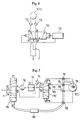
- the air change-over control circuit shown in Fig. 4 is provided with an electromagnetic five-port-two-position change-over valve 70.
- the air source for application of pressure is connected to a port C, and the vacuum source to ports V1 and V2.
- Ports A and B are connected to each air passage by way of filters 72, 72.
- the electromagnetic coils on both sides of the change-over valve 70 are alternately switched through change-over control by a timer circuit 73. Accordingly, in the pumps 1,1, each air passage is alternately changed over to the air side and the vacuum side according to the change-over control of the change-over valve 70 by the timer circuit 73, thereby pumping operation being continuously carried out.
- Fig. 5 shows an embodiment in which the air change-over control circuit is provided with liquid leakage detectors.
- the air source for application of pressure is connected to the port C, while the vacuum source to the ports V1 and V2.
- a pressure gauge 74 for measuring and indicating the air pressure is connected to the port C, while the vacuum source to the ports V1 and V2.
- a pressure gauge 74 for measuring and indicating the air pressure is connected to the port C, while the vacuum source to the ports V1 and V2.
- a pressure gauge 74 for measuring and indicating the air pressure a pressure regulator 75 for regulating the air pressure to a setup pressure
- a filter 76 for eliminating dust contained in the air are respectively connected with an air pressure application line to the port C.
- Each port A, B is connected to each air passage of the pumps 1, 1 by way of the liquid leakage detectors 78 ..., and the pilot port is also connected to the pumps 1, 1 by way of the liquid leakage detectors 78 ....
- the liquid leakage detectors 78 output liquid leakage detection signals when occurring any liquid leakage in the air passage.
- a solenoid operated five-port-two-position change-over valve 79 is provided upstream the filter 76. Line from the filter 76 is connected to the port A of the change-over valve 79, and each port V1, V2 of the change-over valve 70 located downstream is connected to the port B.
- the air source is connected to the port C of the changeover valve 79 located upstream, and the vacuum source is connected to each port V1, V2.
- Signal of the liquid leakage detector 78 is amplified by the amplifier 80, and the electromagnetic solenoid of the change-over valve 79 is operated by the amplified signal to change over the valve. Once the valve is changed over, line for air and the vacuum is closed, and the pumps 1, 1 stop their operation. Air and vacuum are alternately fed to each air passage of the pumps 1, 1 with the change-over operation of the pilot port in the change-over valve 70.
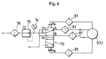
- Fig. 6 shows an embodiment with filters 81 of a porous tetrafluoroetylene resin formed by drawing, which is mounted on the air change-over control circuit.
- the filters 81 are of highly corrosion resistant material and perform a function of permitting gas to get therethrough while inhibiting liquid from passing therethrough, i.e., gas-permeable but not liquid-permeable.
- the pilot ports are changed over to each other so that the air source and the vacuum cource are alternately communicated with each air passage of the pumps 1, 1, thereby the pumps 1, 1 performing their pumping operation.
Landscapes
- Engineering & Computer Science (AREA)
- Mechanical Engineering (AREA)
- General Engineering & Computer Science (AREA)
- Reciprocating Pumps (AREA)
Claims (4)
- Pompe pneumatique pour transporter un fluide corrosif en immergeant le corps principal de la pompe dans le fluide corrosif à transporter, comportant un élément mobile sous la forme d'un soufflet (4) entraîné par une contre-pression d'air dans un cylindre (2) de telle sorte qu'un liquide est aspiré et refoulé par le mouvement alternatif de l'élément mobile (4), caractérisée en ce que toutes les surfaces des éléments qui sont en contact avec le liquide sont formées, soit d'une simple résine fluorée, soit d'un composé d'une telle résine fluorée, tel que PTFE, PFA ou CTFE et en ce que la portion de jonction entre l'élément mobile (4) et une partie de boîtier (7) pour fixer l'élément mobile (4) dans le corps principal de la pompe est soudée circonférentiellement et que la portion de jonction entre cette partie de boîtier (7) et un tube d'air (35) introduit dans la partie de boîtier (7) est soudée circonférentiellement.
- Pompe pneumatique selon la revendication 1, dans laquelle il existe une multiplicité de cylindres (2) et les éléments mobiles (4) sont installés individuellement dans les cylindres (2).
- Pompe pneumatique selon l'une des revendications 1 ou 2, dans laquelle un détecteur de fuite (78) est monté dans un passage d'air du dispositif de pompage et dans lequel il est prévu des moyens (80) pour arrêter l'opération de pompage sur la base de signaux détectés par le détecteur de fuite de liquide (78).
- Pompe pneumatique selon l'une des revendications 1 à 3, dans laquelle un filtre extrêmement résistant à la corrosion (81), perméable aux gaz, mais imperméable aux liquides, est disposé dans le passage d'air du dispositif de pompage.
Applications Claiming Priority (8)
| Application Number | Priority Date | Filing Date | Title |
|---|---|---|---|
| JP61202989A JPH0686872B2 (ja) | 1986-08-28 | 1986-08-28 | 液中浸漬エア駆動形ポンプ |
| JP132204/86U | 1986-08-28 | ||
| JP202990/86 | 1986-08-28 | ||
| JP202989/86 | 1986-08-28 | ||
| JP132205/86U | 1986-08-28 | ||
| JP13220586U JPS6338685U (fr) | 1986-08-28 | 1986-08-28 | |
| JP13220486U JPS6338677U (fr) | 1986-08-28 | 1986-08-28 | |
| JP61202990A JPH0689745B2 (ja) | 1986-08-28 | 1986-08-28 | 液中浸漬エア駆動形ポンプ |
Publications (3)
| Publication Number | Publication Date |
|---|---|
| EP0258541A2 EP0258541A2 (fr) | 1988-03-09 |
| EP0258541A3 EP0258541A3 (en) | 1989-12-06 |
| EP0258541B1 true EP0258541B1 (fr) | 1993-02-03 |
Family
ID=27471666
Family Applications (1)
| Application Number | Title | Priority Date | Filing Date |
|---|---|---|---|
| EP87107829A Expired - Lifetime EP0258541B1 (fr) | 1986-08-28 | 1987-05-29 | Dispositif de pompage pneumatique |
Country Status (3)
| Country | Link |
|---|---|
| US (2) | US4836756A (fr) |
| EP (1) | EP0258541B1 (fr) |
| DE (1) | DE3783972T2 (fr) |
Families Citing this family (24)
| Publication number | Priority date | Publication date | Assignee | Title |
|---|---|---|---|---|
| US4836756A (en) * | 1986-08-28 | 1989-06-06 | Nippon Pillar Packing Co., Ltd. | Pneumatic pumping device |
| US4902206A (en) * | 1988-09-30 | 1990-02-20 | Haluna Kabushiki Kaisha | Bellows pump |
| JPH03179184A (ja) * | 1989-12-05 | 1991-08-05 | Nippon Pillar Packing Co Ltd | 往復動ポンプ |
| US5174722A (en) * | 1991-08-09 | 1992-12-29 | Bomar Corporation | Safety shutdown circuit for pneumatic pump system |
| DE4136805A1 (de) * | 1991-11-08 | 1993-05-13 | Almatec Tech Innovationen Gmbh | Doppelmembranpumpe |
| US5308230A (en) * | 1993-03-08 | 1994-05-03 | Stainless Steel Products, Inc. | Bellows pump |
| US5480292A (en) * | 1993-05-19 | 1996-01-02 | Asti Sae | Dual chamber pump |
| WO1995023924A1 (fr) * | 1994-03-03 | 1995-09-08 | Simmons John M | Pompe a va-et-vient a alternance obtenue par un procede pneumatique |
| US5893707A (en) * | 1994-03-03 | 1999-04-13 | Simmons; John M. | Pneumatically shifted reciprocating pump |
| US5593290A (en) * | 1994-12-22 | 1997-01-14 | Eastman Kodak Company | Micro dispensing positive displacement pump |
| JP3757459B2 (ja) * | 1996-03-21 | 2006-03-22 | 日産自動車株式会社 | ベローズ式燃料ポンプ |
| JP3676890B2 (ja) * | 1996-09-25 | 2005-07-27 | 日本ピラー工業株式会社 | 定量ポンプの逆止弁用樹脂製スプリング及びそれを用いたベローズ式定量ポンプ |
| JP4010585B2 (ja) * | 1996-10-15 | 2007-11-21 | 久光製薬株式会社 | 陰イオン交換樹脂を含有する錠剤 |
| AUPP546598A0 (en) * | 1998-08-26 | 1998-09-17 | Bamford, John O. W. | Flexible cell assembly |
| JP3369523B2 (ja) * | 1999-12-27 | 2003-01-20 | 日本ピラー工業株式会社 | 逆止弁 |
| CA2327012C (fr) | 2000-11-28 | 2006-09-26 | Duncan Wade | Membrane pour pompe a membrane |
| JP2009522526A (ja) * | 2006-01-06 | 2009-06-11 | インテグリス・インコーポレーテッド | 溶接されたダイヤフラムバルブ |
| US7458309B2 (en) * | 2006-05-18 | 2008-12-02 | Simmons Tom M | Reciprocating pump, system or reciprocating pumps, and method of driving reciprocating pumps |
| EP3199812B1 (fr) * | 2014-09-22 | 2019-06-19 | Eagle Industry Co., Ltd. | Système d'alimentation en liquide |
| US20160123313A1 (en) * | 2014-11-05 | 2016-05-05 | Simmons Development, Llc | Pneumatically-operated fluid pump with amplified fluid pressure, and related methods |
| US11092164B2 (en) * | 2015-12-29 | 2021-08-17 | Baker Hughes Esp, Inc. | Non-welded suction chamber for surface pumping systems |
| JP6719323B2 (ja) * | 2016-08-03 | 2020-07-08 | 日本ピラー工業株式会社 | 往復動ポンプ |
| EP3505760A4 (fr) * | 2016-08-23 | 2020-01-22 | Eagle Industry Co., Ltd. | Système d'alimentation en liquide |
| DE102021003639A1 (de) * | 2021-07-14 | 2023-01-19 | Hydac Technology Gmbh | Fördereinrichtung |
Family Cites Families (19)
| Publication number | Priority date | Publication date | Assignee | Title |
|---|---|---|---|---|
| US862867A (en) * | 1906-03-28 | 1907-08-06 | Lewis Watson Eggleston | Pneumatic pumping apparatus. |
| US1408208A (en) * | 1917-05-25 | 1922-02-28 | Joseph W Jones | Liquid-fuel-feeding device for internal-combustion engines |
| US2383486A (en) * | 1939-02-08 | 1945-08-28 | Perishables Shipping Equipment | Refrigeration mechanism |
| US2239270A (en) * | 1940-01-31 | 1941-04-22 | John L Hutton | Device for detecting pump failure |
| FR1164314A (fr) * | 1956-11-26 | 1958-10-08 | Perfectionnements aux membranes déformables | |
| US3022737A (en) * | 1959-05-06 | 1962-02-27 | Walbro Corp | Fuel pump |
| US3176623A (en) * | 1962-07-20 | 1965-04-06 | American Instr Co Inc | Protective system for a diaphragm pump |
| US3257952A (en) * | 1964-06-29 | 1966-06-28 | Alan G Mccormick | Bellows pump |
| US3524714A (en) * | 1968-10-30 | 1970-08-18 | Us Air Force | Pneumatic bellows pump |
| US3597120A (en) * | 1969-05-14 | 1971-08-03 | John H Reed | Injector-recirculation pump |
| US3683600A (en) * | 1970-06-03 | 1972-08-15 | American Crucible Products Co | Filter apparatus to protect a switch chamber against moisture |
| US3661060A (en) * | 1970-08-05 | 1972-05-09 | Duriron Co | Diaphragms for high pressure compressors and pumps |
| JPS5242000B2 (fr) * | 1973-10-01 | 1977-10-21 | ||
| US4303376A (en) * | 1979-07-09 | 1981-12-01 | Baxter Travenol Laboratories, Inc. | Flow metering cassette and controller |
| US4489779A (en) * | 1983-02-28 | 1984-12-25 | Quantitative Environmental Decisions Corporation | Fluid sampling apparatus |
| DE3408331C2 (de) * | 1984-03-07 | 1986-06-12 | Fresenius AG, 6380 Bad Homburg | Pumpanordnung für medizinische Zwecke |
| US4681518A (en) * | 1985-02-19 | 1987-07-21 | The Coca-Cola Company | Single-acting, gas operated pump |
| DE8525733U1 (de) * | 1985-09-10 | 1987-01-15 | Becker, Erich, 7812 Bad Krozingen | Membranpumpe |
| US4836756A (en) * | 1986-08-28 | 1989-06-06 | Nippon Pillar Packing Co., Ltd. | Pneumatic pumping device |
-
1987
- 1987-05-26 US US07/053,779 patent/US4836756A/en not_active Expired - Lifetime
- 1987-05-29 DE DE8787107829T patent/DE3783972T2/de not_active Expired - Fee Related
- 1987-05-29 EP EP87107829A patent/EP0258541B1/fr not_active Expired - Lifetime
-
1991
- 1991-10-25 US US07/781,652 patent/US5158439A/en not_active Expired - Fee Related
Also Published As
| Publication number | Publication date |
|---|---|
| EP0258541A3 (en) | 1989-12-06 |
| DE3783972D1 (de) | 1993-03-18 |
| US5158439A (en) | 1992-10-27 |
| US4836756A (en) | 1989-06-06 |
| EP0258541A2 (fr) | 1988-03-09 |
| DE3783972T2 (de) | 1993-05-27 |
Similar Documents
| Publication | Publication Date | Title |
|---|---|---|
| EP0258541B1 (fr) | Dispositif de pompage pneumatique | |
| US6464474B2 (en) | Nonrespiratory diaphragm chucking | |
| US20110163540A1 (en) | O-ringless seal couplings | |
| US6582206B2 (en) | Diaphragm chucking with elasticity adjustment | |
| US5645301A (en) | Fluid transport coupling | |
| JP6851198B2 (ja) | 真空システムのパイプカップリング | |
| JPH05240161A (ja) | 複成隔膜ポンプ | |
| JP2001525538A (ja) | 汚染を生じない圧力トランスデューサモジュール | |
| KR19990024027A (ko) | 조절가능한 누출방지 체결시스템 | |
| US4186776A (en) | Pulsation dampener or surge absorber | |
| US4817994A (en) | Aseptic pipe joint | |
| KR102541108B1 (ko) | 플랜지 어셈블리 | |
| US5443290A (en) | Floating ring expansion joint liner seal | |
| CA1206376A (fr) | Pompe a diaphragme | |
| EP0912830B1 (fr) | Pompe a piston a commande pneumatique et membrane a enroulement | |
| CA2154007C (fr) | Microsoupape destinee a un systeme d'alimentation en fluide | |
| JP4383618B2 (ja) | 自動弁 | |
| US20240426410A1 (en) | I-bridge | |
| JP4741575B2 (ja) | 高圧分析機器のための流体制御装置 | |
| CN100451412C (zh) | 阀以及具有该阀的流体系统 | |
| GB2073391A (en) | Refrigeration installation | |
| EP0777259A1 (fr) | Appareil pour le transport d'un fluide vers un lieu d'utilisation | |
| CN121048043B (zh) | 管路连接装置及半导体设备 | |
| CN209961428U (zh) | 法兰密封连接状态的密封监测系统 | |
| JP4502651B2 (ja) | 弁およびその弁を有する流体システム |
Legal Events
| Date | Code | Title | Description |
|---|---|---|---|
| PUAI | Public reference made under article 153(3) epc to a published international application that has entered the european phase |
Free format text: ORIGINAL CODE: 0009012 |
|
| AK | Designated contracting states |
Kind code of ref document: A2 Designated state(s): DE FR NL |
|
| PUAL | Search report despatched |
Free format text: ORIGINAL CODE: 0009013 |
|
| AK | Designated contracting states |
Kind code of ref document: A3 Designated state(s): DE FR NL |
|
| 17P | Request for examination filed |
Effective date: 19900510 |
|
| 17Q | First examination report despatched |
Effective date: 19901210 |
|
| GRAA | (expected) grant |
Free format text: ORIGINAL CODE: 0009210 |
|
| AK | Designated contracting states |
Kind code of ref document: B1 Designated state(s): DE FR NL |
|
| ET | Fr: translation filed | ||
| REF | Corresponds to: |
Ref document number: 3783972 Country of ref document: DE Date of ref document: 19930318 |
|
| PLBE | No opposition filed within time limit |
Free format text: ORIGINAL CODE: 0009261 |
|
| STAA | Information on the status of an ep patent application or granted ep patent |
Free format text: STATUS: NO OPPOSITION FILED WITHIN TIME LIMIT |
|
| 26N | No opposition filed | ||
| PGFP | Annual fee paid to national office [announced via postgrant information from national office to epo] |
Ref country code: FR Payment date: 19960416 Year of fee payment: 10 |
|
| PGFP | Annual fee paid to national office [announced via postgrant information from national office to epo] |
Ref country code: NL Payment date: 19960529 Year of fee payment: 10 |
|
| PGFP | Annual fee paid to national office [announced via postgrant information from national office to epo] |
Ref country code: DE Payment date: 19960531 Year of fee payment: 10 |
|
| PG25 | Lapsed in a contracting state [announced via postgrant information from national office to epo] |
Ref country code: NL Effective date: 19971201 |
|
| PG25 | Lapsed in a contracting state [announced via postgrant information from national office to epo] |
Ref country code: FR Free format text: LAPSE BECAUSE OF NON-PAYMENT OF DUE FEES Effective date: 19980130 |
|
| NLV4 | Nl: lapsed or anulled due to non-payment of the annual fee |
Effective date: 19971201 |
|
| PG25 | Lapsed in a contracting state [announced via postgrant information from national office to epo] |
Ref country code: DE Free format text: LAPSE BECAUSE OF NON-PAYMENT OF DUE FEES Effective date: 19980203 |
|
| REG | Reference to a national code |
Ref country code: FR Ref legal event code: ST |