EP0258576A2 - Réseau isolant des courants harmoniques - Google Patents
Réseau isolant des courants harmoniques Download PDFInfo
- Publication number
- EP0258576A2 EP0258576A2 EP87109834A EP87109834A EP0258576A2 EP 0258576 A2 EP0258576 A2 EP 0258576A2 EP 87109834 A EP87109834 A EP 87109834A EP 87109834 A EP87109834 A EP 87109834A EP 0258576 A2 EP0258576 A2 EP 0258576A2
- Authority
- EP
- European Patent Office
- Prior art keywords
- inductor
- reflector
- terminal
- capacitor
- terminals
- Prior art date
- Legal status (The legal status is an assumption and is not a legal conclusion. Google has not performed a legal analysis and makes no representation as to the accuracy of the status listed.)
- Granted
Links
- 239000003990 capacitor Substances 0.000 claims abstract description 109
- 239000004020 conductor Substances 0.000 abstract description 9
- 230000008901 benefit Effects 0.000 description 5
- 238000010586 diagram Methods 0.000 description 3
- 230000009467 reduction Effects 0.000 description 3
- 230000004075 alteration Effects 0.000 description 2
- 230000005540 biological transmission Effects 0.000 description 2
- 238000012986 modification Methods 0.000 description 2
- 230000004048 modification Effects 0.000 description 2
- 230000001360 synchronised effect Effects 0.000 description 2
- 238000004590 computer program Methods 0.000 description 1
- 230000007123 defense Effects 0.000 description 1
- 230000000694 effects Effects 0.000 description 1
- 230000006698 induction Effects 0.000 description 1
- 230000001939 inductive effect Effects 0.000 description 1
- 230000000063 preceeding effect Effects 0.000 description 1
- 239000000779 smoke Substances 0.000 description 1
- 230000003068 static effect Effects 0.000 description 1
- 230000007474 system interaction Effects 0.000 description 1
Images
Classifications
-
- H—ELECTRICITY
- H03—ELECTRONIC CIRCUITRY
- H03H—IMPEDANCE NETWORKS, e.g. RESONANT CIRCUITS; RESONATORS
- H03H7/00—Multiple-port networks comprising only passive electrical elements as network components
- H03H7/01—Frequency selective two-port networks
- H03H7/0115—Frequency selective two-port networks comprising only inductors and capacitors
-
- H—ELECTRICITY
- H02—GENERATION; CONVERSION OR DISTRIBUTION OF ELECTRIC POWER
- H02M—APPARATUS FOR CONVERSION BETWEEN AC AND AC, BETWEEN AC AND DC, OR BETWEEN DC AND DC, AND FOR USE WITH MAINS OR SIMILAR POWER SUPPLY SYSTEMS; CONVERSION OF DC OR AC INPUT POWER INTO SURGE OUTPUT POWER; CONTROL OR REGULATION THEREOF
- H02M1/00—Details of apparatus for conversion
- H02M1/12—Arrangements for reducing harmonics from AC input or output
Definitions
- the present invention relates to the power factor which loads present to AC power lines generally and more specifically to the reduction of the harmonic currents generated on an AC power line by a DC power supply.
- DC power supplies employ a bridge rectifier, a filter capacitor, and, sometimes, a filter choke.
- the input of the rectifier is coupled (by a fuse, switch, etc.) across an AC power line.
- the output of the rectifier is either coupled by the choke across the capacitor (choke input filter) or, absent the choke, directly connected across the capacitor (capacitor input filter) to develop a DC (output) potential across the capacitor.
- DC power supplies draw from the AC power line a current the waveform of which approximates a square wave (when the inductance of the choke is much greater than what is commonly referred to as the "critical" inductance). Absent the choke, the waveform more approximates a series of pulses each of which is synchronized with a corresponding peak of the AC power-line potential. In either case, the current drawn from the AC power line includes harmonic components (currents), one for each of the odd harmonics of the AC power-line frequency. DC power supplies do not conform to all of the old power factor conventions.
- DC power supply presents to an AC power line as the cosine of the phase angle between the voltage developed across the input of the DC power supply and the current flowing into it.
- DC power supplies do present many of the same problems.
- DC power supplies like other loads having a relatively low power factor, draw from the AC power line a current the rms level of which is disproportionately high in relation to the current that should be drawn for the power consumed.
- the power factor of a load in this case, a DC power supply
- the ratio of the actual power consumed in this case by a load connected to the output of the DC power supply) (as indicated by a wattmeter) to the apparent power (as indicated by the combination of a (true rms, iron-vane or thermocouple-type) ammeter and a voltmeter) (connected to the input of the DC power supply).
- a relatively high AC power-line rms current is of concern in that the AC power-generating facilities and AC power-transmission facilities (lines and transformers) must be sized to accommodate the current. Further, generation and transmission losses are primarily resistive losses which, therefore, increase as the square of the level of the rms AC power-line current. It is important to note that even relatively small loads (DC power supplies) may be of concern. Although a small personal computer, for example, may not draw the level of the current drawn by a large smoke stack scrubber, if the DC power supply of the computer has a relatively low power factor, the current drawn by the DC power supply may be of such a level as to limit what may also be plugged into a single AC power-line wall outlet.
- a prior-art-type circuit for improving the power factor a DC power supply presents to an AC power line is shown in the German patent number DE 3012-747 and the Japanese patent number 58-163271. Both circuits include an inductor and a capacitor which is connected in parallel with the inductor.
- the inductor-capacitor combination is connected between the AC power line and the input of the bridge rectifier of a (capacitor-input-filter-type) DC power supply to couple the DC power supply to the AC power line.
- the inductor-capacitor combination is usually tuned to the fifth but maybe the ninth or thirteenth harmonic of the AC power-line frequency.
- the purpose of the inductor-capacitor combination is to reduce the level of the third and fifth harmonic waves (currents?).
- the above-mentioned inductor-capacitor combination may increase the level of other harmonic currents.
- the use of the above mentioned inductor-capacitor combination may reduce the level of the DC output potential developed by the associated DC power supply.
- the filter network employs a plurality of filters each including an inductor and a capacitor which is connected in series with the (associated) inductor. Each of the filters (inductor-capacitor combinations) is connected in parallel with the load. An additional inductor is employed connected between the AC power line and the load to couple the load to the AC power line. It is indicated (on page 2 in lines 113-115 of the British patent) that each of the filters (inductor-capacitor combinations) is tuned to a frequency less than the harmonic frequency which it is to filter.
- the level of the third harmonic current was 88 percent
- the level of the fifth harmonic current was 65 percent
- the level of the seventh harmonic current was 38 percent of the level of the fundamental current.
- the DC power supply was found to present a power factor of 94 percent to the AC power line.
- the level of the third harmonic current was 20 percent
- the level of the fifth harmonic current was 6 percent
- the level of the seventh harmonic current was 2 percent of the level of the fundamental current.
- Another object of the present invention to provide a means by which DC power supplies may be made to meet commercial/industrial standards.
- Another object of the present invention is to provide a means by which the levels of harmonic currents generated on an AC power line by a DC power supply may be reduced.
- Still another object of the present invention is to provide a means by which the power factor a DC power supply presents to an AC power line may be improved.
- the preferred embodiment of the present invention employs three similiar portions each connected between a respective conductor of a (three phase) AC power line and a respective conductor of a DC power supply.
- Each of the portions includes the series combination of three "reflectors" each having the parallel resonant combination of an inductor and a capacitor.
- three series resonant inductor-capacitor combinations are employed each connected between a unique pair of the DC power supply conductors.
- Another advantage of the present invention is the ability it affords to provide a means by which DC power supplies may be made to meet commercial/industrial standards.
- Another advantage of the present invention is the ability it affords to provide a means by which the levels of harmonic currents generated on an AC power line by a DC power supply may be reduced.
- Still another advantage of the present invention is the ability it affords to provide a means by which the power factor a DC power supply presents to an AC power line may be improved.
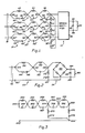
- FIGURE 1 of the drawing generally designated by the number 10 is the presently preferred embodiment of a military grade network for isolating from an AC power line the harmonic currents generated by a DC power supply.
- network 10 is also illustrated with network 10 is a (three phase) AC power line, generally designated 12, and a (capacitor-input-type) DC power supply, generally designated 14.
- Network 10 is shown to employ three terminals (nodes), respectively designated 20, 20 ⁇ , and 20 ⁇ , each for connection to a respective conductor of AC power line 12 and three terminals (nodes), respectively designated 22, 22 ⁇ , and 22 ⁇ , each for connection to DC power supply 14.
- Network 10 also employs three similiar portions, respectively designated 30, 30 ⁇ , and 30 ⁇ , each connected between a respective one of terminals 20, 20 ⁇ , and 20 ⁇ and a respective one of terminals 22, 22 ⁇ , and 22 ⁇ . (Herein, similiar portions/components are similiarly numbered.) Additionally, network 10 employs three similiar portions, respectively designated 32, 32 ⁇ , and 32 ⁇ , each connected between a respective pair of terminals 20 and 20 ⁇ , 20 ⁇ and 20 ⁇ , and 20 ⁇ and 20.
- Portion 30 includes an inductor (choke) 40 which is connected between terminal 20 and a node 42. Additionally, portion 30 includes a resistor 44 and a capacitor 46 which are connected in series between terminal 20 and node 42. Further, portion 30 includes an inductor 50 and a capacitor 52, the combination (of inductor 50 and capacitor 52) being connected in parallel (parallel resonant) between node 42 and a node 54. Finally, portion 30 includes an inductor 58 and a capacitor 60, the combination (of inductor 58 and capacitor 60) being connected in parallel (parallel resonant) between node 54 and terminal 22.
- Portion 32 includes an inductor 70 and a capacitor 72, the combination (of inductor 70 and capacitor 72) being connected in series (series resonant) between terminals nodes 22 and 22 ⁇ .
- DC power supply 14 employs a bridge rectifier 80 and a filter capacitor 82.
- the input of rectifier 80 is connected to terminals 22, 22 ⁇ , and 22 ⁇ ; and, the output of the rectifier is (in this case) directly connected across capacitor 82 (between a pair of terminals 84 and 86) to develop a DC (output) potential (between the terminals) across the capacitor.
- a load (for DC power supply 14) is represented by a resistor 90 connected between terminals 84 and 86.
- Bridge rectifier 80 includes three rectifier diodes (not shown) each having a cathode coupled to terminal 84 and an anode coupled to a respective one of terminals 22, 22 ⁇ , and 22 ⁇ . Further, bridge rectifier 80 includes three more diodes (also not shown) each having an anode coupled to terminal 86 and a cathode coupled to a respective one of terminals 22, 22 ⁇ , and 22 ⁇ .
- the inductor (70, 70 ⁇ , or 70 ⁇ ) and capacitor (72, 72 ⁇ , or 72 ⁇ ) combination of each of portions 32, 32 ⁇ , and 32 ⁇ form (what is referred to herein as) a "resonator" for (it is believed) (in conjunction with power supply 14) generating harmonic currents for the power supply.
- the inductance of the inductor (70, 70 ⁇ , or 70 ⁇ ) and the capacitance of the capacitor (72, 72 ⁇ , or 72 ⁇ ) are chosen such that each inductor-capacitor combination resonates at a frequency near the sixth harmonic frequency of the power-line frequency and has a Q of approximately one to generate currents at both the fifth and the seventh harmonic frequencies.
- inductor-capacitor combinations of portion 30 (40 and 46, 50 and 52, and 58 and 60) (as well as the similiar combinations of portions 30 ⁇ and 30 ⁇ ) form (what is referred to herein as) "reflectors" for (it is believed) reflecting harmonic energy back toward power supply 14.
- inductor 58 and capacitor 60 resonate near the seventh harmonic frequency
- inductor 50 and capacitor 52 resonate near the fifth harmonic frequency
- inductor 40 and capacitor 46 resonate near the thirteenth harmonic frequency.
- Each of the inductor-capacitor combinations of the "reflectors" have a Q which is in the range of 0.5 to 3.
- a low "reflector” Q is employed to, among other things, avoid excessively attenuating the level of the fundamental current.
- a resistor (44) is included in series with the capacitor (46) in the highest frequency “resonator”.
- the resistor (44) resistance is approximately equal to the characteristic impedance of each of the "resonators” (each of portions 32, 32 ⁇ , and 32 ⁇ ).
- no inductor-capacitor combination resonates at an exact multiple of the resonate frequency of another inductor-capacitor combination; because, it has been observed that certain combinations of frequency and Q have resulted in excessive levels of harmonic currents in the line.
- inductor 40 .... 2.41 mH, resistor 44 .... 12 ohms, capacitor 46 ... 23.2 mfd, inductor 50 .... 2.84 mH, capacitor 52 ... 97.4 mfd, inductor 58 .... 2.43 mH, capacitor 60 ... 46.9 mfd, inductor 70 .... 3.55 mH, capacitor 72 ... 10.95 mfd, capacitor 82 ... 3000 mfd, and resistor 90 .... a constant 2000 watt load (such as is presented by a switching power supply and its load).
- FIGURE 2 the presently preferred embodiment of a commercial/industrial grade harmonic currents isolating network is illustrated generally designated 110.
- network 110 is illustrated a (single phase) AC power line, generally designated 112, and another (capacitor-input-type) DC power supply, generally designated 114.
- Network 110 is shown to employ two terminals (nodes), respectively designated 120 and 120 ⁇ , each for connection to a respective conductor of AC power line 112 and two terminals (nodes), respectively designated 122 and 122 ⁇ , each for connection to DC power supply 114.
- Network 110 employs two “reflectors” and one " resonator".
- the first “reflector” includes an inductor 140, which is connected between terminal 120 and a node 142. Additionally, the first “reflector” includes a resistor 144 and a capacitor 146 which is connected in series with resistor 144 between terminal 120 and node 142.
- the second “reflector” includes another inductor 150 and another capacitor 152 which are connected in parallel between node 142 and terminal 122.
- the "resonator” includes still another inductor 170 and still another capacitor 172 connected in series between terminals 122 and 122 ⁇ . Terminal 120 ⁇ is directly coupled (connected) to terminal 122 ⁇ .
- DC power supply 114 employs a bridge rectifier 180 and a filter capacitor 182.
- the input of rectifier 180 is connected to terminals 122 and 122 ⁇ ; and, the output of the rectifier is directly connected across capacitor 182 (between a pair of terminals 184 and 186) to develop a DC (output) potential (between the terminals) across the capacitor.
- a load for DC power supply 104) is represented by a resistor 190 connected between terminals 184 and 186.
- the inductance of the inductor (170) and the capacitance of the capacitor (172) of the "resonator” are chosen such that they resonate at a frequency near the sixth harmonic frequency of the power-line frequency and have a Q of approximately one to generate currents at both the fifth and the seventh harmonic frequencies.
- the (inductor 170 and capacitor 172) "resonator” generates an appreciable amount of third harmonic current without the high no load voltage characteristic of a "resonator” resonate at a lower frequency.
- the "reflector” which includes inductor 150 and capacitor 152 resonates at a frequency near the fifth harmonic frequency and has a Q of approximately one.
- the other "reflector" which includes inductor 140 and capacitor 146, resonates near the seventh harmonic frequency and has a Q of approximately 3/4.
- the resistor (144) resistance is approximately equal to the characteristic impedance of the "resonator”.
- inductor 140 ... 36 mH, resistor 144 .... 115 ohms, capacitor 146 ... 4.84 mfd, inductor 150 .... 67.2 mH, capacitor 152 ... 5.08 mfd, inductor 170 .... 56.5 mH, capacitor 172 ... 4,27 mfd, capacitor 182 ... 600 mfd, and resistor 190 .... a constant 200 ohm resistive load consuming approximately 100 watts.
- FIGURE 3 a commercial/industrial grade harmonic currents isolating network is illustrated in FIGURE 3 generally designated 210.
- Network 210 employs two terminals (nodes), respectively designated 220 and 220 ⁇ , each for connection to a respective conductor of an AC power line and two terminals (nodes), respectively designated 222 and 222 ⁇ , each for connection to a DC power supply. Additionally, network 210 employs five "reflectors" connected in series between terminals 220 and 222 and two "resonators".
- the first three “reflectors” include the parallel connection of an inductor 240 and a resistor 244 in the first; the parallel connection of an inductor 250 and a capacitor 252 in the second; and an inductor 258 and a capacitor 260 in the third.
- the first "resonator” Connected between the third and fourth "reflector”, the first "resonator” includes an inductor 270 and a capacitor 272 connected in series between a node 274 and terminal 222 ⁇ .
- the last two “reflectors” include the parallel combination of an inductor 340 and a capacitor 346 in the fourth and the parallel connection of an inductor 350 and a capacitor 352 in the fifth.
- the last (second) “resonator” includes an inductor 370 and a capacitor 372 connected in series between terminals 222 and 222 ⁇ . Terminal 220 ⁇ is directly coupled (connected) to terminal 222 ⁇ .
- inductor 240 .... 30 mH, resistor 244 .... 115 ohms, inductor 250 .... 30.5 mH, capacitor 252 ... 9.23 mfd, .. freq. ... 5th harmonic, Q ... 1/2, inductor 258 .... 21.8 mH, capacitor 260 ... 6.59 mfd, .. freq. ... 7th harmonic, Q ... 1/2, inductor 270 .... 102 mH, capacitor 272 ... 7.66 mfd, .. freq. ... 3rd harmonic, Q ... 1, inductor 340 .... 16.9 mH, capacitor 346 ...
- the components employed are all passive, they may be scaled up or down.
- the ratio of the desired power rating to the given power rating is obtained.
- the inductance of each of the inductors is divided by the ratio; the capacitance of each of the capacitors is multiplied by the ratio; and, the resistance of each of the resistors is divided by the ratio.
- inductor 270 and capacitor 272 are connected in series between terminal 222 ⁇ and a node 400 at the juncture of inductors 340 and 350.
Landscapes
- Engineering & Computer Science (AREA)
- Power Engineering (AREA)
- Insulated Conductors (AREA)
- Supply And Distribution Of Alternating Current (AREA)
- Hydrogenated Pyridines (AREA)
- Inverter Devices (AREA)
- Power Conversion In General (AREA)
- Rectifiers (AREA)
- Microwave Amplifiers (AREA)
Priority Applications (1)
| Application Number | Priority Date | Filing Date | Title |
|---|---|---|---|
| AT87109834T ATE87148T1 (de) | 1986-07-23 | 1987-07-08 | Harmonische stroeme isolierendes netz. |
Applications Claiming Priority (2)
| Application Number | Priority Date | Filing Date | Title |
|---|---|---|---|
| US06/888,137 US5113335A (en) | 1986-07-23 | 1986-07-23 | Harmonic currents isolating network |
| US888137 | 1986-07-23 |
Publications (3)
| Publication Number | Publication Date |
|---|---|
| EP0258576A2 true EP0258576A2 (fr) | 1988-03-09 |
| EP0258576A3 EP0258576A3 (en) | 1988-09-28 |
| EP0258576B1 EP0258576B1 (fr) | 1993-03-17 |
Family
ID=25392599
Family Applications (1)
| Application Number | Title | Priority Date | Filing Date |
|---|---|---|---|
| EP87109834A Expired - Lifetime EP0258576B1 (fr) | 1986-07-23 | 1987-07-08 | Réseau isolant des courants harmoniques |
Country Status (5)
| Country | Link |
|---|---|
| US (1) | US5113335A (fr) |
| EP (1) | EP0258576B1 (fr) |
| JP (1) | JPS6335167A (fr) |
| AT (1) | ATE87148T1 (fr) |
| DE (1) | DE3784813T2 (fr) |
Cited By (3)
| Publication number | Priority date | Publication date | Assignee | Title |
|---|---|---|---|---|
| US4930061A (en) * | 1989-04-07 | 1990-05-29 | At&T Bell Laboratories | Method and network for enhancing power factor of off-line switching circuit |
| US5251120A (en) * | 1986-07-23 | 1993-10-05 | Steve Smith | Harmonic noise isolation and power factor correction network |
| CN102624349A (zh) * | 2012-03-15 | 2012-08-01 | 北京航空航天大学 | 一种对原始数据低失真的谐波噪声干扰和白噪声干扰的去除方法 |
Families Citing this family (4)
| Publication number | Priority date | Publication date | Assignee | Title |
|---|---|---|---|---|
| US5416687A (en) * | 1992-06-23 | 1995-05-16 | Delta Coventry Corporation | Power factor correction circuit for AC to DC power supply |
| US5750918A (en) * | 1995-10-17 | 1998-05-12 | Foster-Miller, Inc. | Ballistically deployed restraining net |
| US5691577A (en) * | 1996-05-03 | 1997-11-25 | Smith; Steve | Reflector-pump network for preempting AC power supply harmonic distortion and for satiating the complex harmonic power demand of a rectifier |
| US6985370B2 (en) * | 2002-05-24 | 2006-01-10 | David Kerstetter | AC power line filter |
Family Cites Families (14)
| Publication number | Priority date | Publication date | Assignee | Title |
|---|---|---|---|---|
| GB221850A (en) * | 1923-06-12 | 1924-09-12 | Ernest Yeoman Robinson | Improvements in or relating to the rectification of alternating-current |
| GB462823A (en) * | 1935-08-12 | 1937-03-12 | Emi Ltd | Improvements in and relating to the supply of electrical energy to varying loads, for example thermionic valve apparatus |
| US2138996A (en) * | 1935-08-12 | 1938-12-06 | Emi Ltd | Electrical network |
| DE659504C (de) * | 1938-05-04 | Friedrich Conrad Dr | Entstoerungseinrichtung fuer Hochspannungsleitungen | |
| US3461372A (en) * | 1965-01-22 | 1969-08-12 | Int Standard Electric Corp | D.c. to a.c. power converter |
| FR1439771A (fr) * | 1965-07-15 | 1966-05-20 | Licentia Gmbh | Dispositif de suppression des harmoniques d'une tension alternative |
| DE1927415A1 (de) * | 1968-06-14 | 1970-01-02 | Ass Elect Ind | Anordnung zur Hochspannungs-Gleichstromuebertragung |
| JPS5244192A (en) * | 1975-10-06 | 1977-04-06 | Hitachi Ltd | Optical integrated circuit |
| US4222096A (en) * | 1978-12-05 | 1980-09-09 | Lutron Electronics Co., Inc. | D-C Power supply circuit with high power factor |
| DE2950411C2 (de) * | 1979-12-14 | 1986-07-03 | Patent-Treuhand-Gesellschaft Fuer Elektrische Gluehlampen Mbh, 8000 Muenchen | Gleichrichtervorrichtung mit gesiebter Ausgangsspannung |
| DE3012747C2 (de) * | 1980-03-28 | 1983-12-29 | Licentia Patent-Verwaltungs-Gmbh, 6000 Frankfurt | Netzteil mit Wechselspannungseingang und Gleichrichtern |
| JPS56157261A (en) * | 1980-05-07 | 1981-12-04 | Ricoh Co Ltd | Power source |
| JPS58163271A (ja) * | 1982-03-19 | 1983-09-28 | Hitachi Ltd | 空気調和装置の力率改善回路 |
| US4591963A (en) * | 1984-04-23 | 1986-05-27 | At&T Bell Laboratories | Technique for reducing line current harmonics at input to power supply acting as nonlinear load |
-
1986
- 1986-07-23 US US06/888,137 patent/US5113335A/en not_active Expired - Lifetime
-
1987
- 1987-07-08 AT AT87109834T patent/ATE87148T1/de not_active IP Right Cessation
- 1987-07-08 EP EP87109834A patent/EP0258576B1/fr not_active Expired - Lifetime
- 1987-07-08 DE DE8787109834T patent/DE3784813T2/de not_active Expired - Fee Related
- 1987-07-22 JP JP62183245A patent/JPS6335167A/ja active Pending
Cited By (4)
| Publication number | Priority date | Publication date | Assignee | Title |
|---|---|---|---|---|
| US5251120A (en) * | 1986-07-23 | 1993-10-05 | Steve Smith | Harmonic noise isolation and power factor correction network |
| US4930061A (en) * | 1989-04-07 | 1990-05-29 | At&T Bell Laboratories | Method and network for enhancing power factor of off-line switching circuit |
| CN102624349A (zh) * | 2012-03-15 | 2012-08-01 | 北京航空航天大学 | 一种对原始数据低失真的谐波噪声干扰和白噪声干扰的去除方法 |
| CN102624349B (zh) * | 2012-03-15 | 2014-09-17 | 北京航空航天大学 | 一种对原始数据低失真的谐波噪声干扰和白噪声干扰的去除方法 |
Also Published As
| Publication number | Publication date |
|---|---|
| ATE87148T1 (de) | 1993-04-15 |
| DE3784813T2 (de) | 1993-06-24 |
| JPS6335167A (ja) | 1988-02-15 |
| US5113335A (en) | 1992-05-12 |
| EP0258576A3 (en) | 1988-09-28 |
| EP0258576B1 (fr) | 1993-03-17 |
| DE3784813D1 (de) | 1993-04-22 |
Similar Documents
| Publication | Publication Date | Title |
|---|---|---|
| US5251120A (en) | Harmonic noise isolation and power factor correction network | |
| US4369490A (en) | Low-ripple power rectifier system | |
| Gonzalez et al. | Design of filters to reduce harmonic distortion in industrial power systems | |
| US4782268A (en) | Low-pressure discharge lamp, particularly fluorescent lamp high-frequency operating circuit with low-power network interference | |
| US5844791A (en) | Single-phase harmonic filter system | |
| US4143414A (en) | Three phase ac to dc voltage converter with power line harmonic current reduction | |
| US5387821A (en) | Power distribution circuit with power factor correction and independent harmonic current filter | |
| US5323304A (en) | A.C. storage module for reducing harmonic distortion in an A.C. waveform | |
| US5635825A (en) | Power factor corrected feedforward coupled DC power supply | |
| EP0258576B1 (fr) | Réseau isolant des courants harmoniques | |
| US5805032A (en) | Electrical filter for attenuating oscillations in AC mains | |
| JPH01206841A (ja) | 高域通過フイルタ | |
| US6844794B2 (en) | Harmonic mitigating filter | |
| US4914559A (en) | Power factor improving arrangement | |
| US5659464A (en) | Filter for pulse width modulating inverter | |
| CN1065371C (zh) | 电路 | |
| US5814901A (en) | Harmonic blocking at source transformer | |
| EP3394971B1 (fr) | Système de mise à la masse pour système de conversion de puissance | |
| US5691577A (en) | Reflector-pump network for preempting AC power supply harmonic distortion and for satiating the complex harmonic power demand of a rectifier | |
| JPH044814B2 (fr) | ||
| RU205207U1 (ru) | Пассивный LC-фильтр, адаптированный к колебаниям частоты источника питания | |
| JP3319216B2 (ja) | 定電圧高調波吸収電源装置 | |
| CA1304448C (fr) | Dispositif pour accroitre le facteur de puissance | |
| Hsu | Reactive power compensator with harmonic blocking feature | |
| JPS63114531A (ja) | 高調波防止抑制装置 |
Legal Events
| Date | Code | Title | Description |
|---|---|---|---|
| PUAI | Public reference made under article 153(3) epc to a published international application that has entered the european phase |
Free format text: ORIGINAL CODE: 0009012 |
|
| 17P | Request for examination filed |
Effective date: 19870708 |
|
| AK | Designated contracting states |
Kind code of ref document: A2 Designated state(s): AT BE CH DE ES FR GB GR IT LI LU NL SE |
|
| PUAL | Search report despatched |
Free format text: ORIGINAL CODE: 0009013 |
|
| AK | Designated contracting states |
Kind code of ref document: A3 Designated state(s): AT BE CH DE ES FR GB GR IT LI LU NL SE |
|
| 17Q | First examination report despatched |
Effective date: 19890602 |
|
| ITF | It: translation for a ep patent filed | ||
| GRAA | (expected) grant |
Free format text: ORIGINAL CODE: 0009210 |
|
| AK | Designated contracting states |
Kind code of ref document: B1 Designated state(s): AT BE CH DE ES FR GB GR IT LI LU NL SE |
|
| PG25 | Lapsed in a contracting state [announced via postgrant information from national office to epo] |
Ref country code: GR Free format text: LAPSE BECAUSE OF FAILURE TO SUBMIT A TRANSLATION OF THE DESCRIPTION OR TO PAY THE FEE WITHIN THE PRESCRIBED TIME-LIMIT Effective date: 19930317 |
|
| REF | Corresponds to: |
Ref document number: 87148 Country of ref document: AT Date of ref document: 19930415 Kind code of ref document: T |
|
| REF | Corresponds to: |
Ref document number: 3784813 Country of ref document: DE Date of ref document: 19930422 |
|
| ET | Fr: translation filed | ||
| PG25 | Lapsed in a contracting state [announced via postgrant information from national office to epo] |
Ref country code: ES Free format text: LAPSE BECAUSE OF FAILURE TO SUBMIT A TRANSLATION OF THE DESCRIPTION OR TO PAY THE FEE WITHIN THE PRESCRIBED TIME-LIMIT Effective date: 19930628 |
|
| PG25 | Lapsed in a contracting state [announced via postgrant information from national office to epo] |
Ref country code: LU Free format text: LAPSE BECAUSE OF NON-PAYMENT OF DUE FEES Effective date: 19930731 |
|
| PLBE | No opposition filed within time limit |
Free format text: ORIGINAL CODE: 0009261 |
|
| STAA | Information on the status of an ep patent application or granted ep patent |
Free format text: STATUS: NO OPPOSITION FILED WITHIN TIME LIMIT |
|
| 26N | No opposition filed | ||
| EAL | Se: european patent in force in sweden |
Ref document number: 87109834.9 |
|
| PGFP | Annual fee paid to national office [announced via postgrant information from national office to epo] |
Ref country code: DE Payment date: 20010702 Year of fee payment: 15 |
|
| PGFP | Annual fee paid to national office [announced via postgrant information from national office to epo] |
Ref country code: SE Payment date: 20010704 Year of fee payment: 15 Ref country code: GB Payment date: 20010704 Year of fee payment: 15 |
|
| PGFP | Annual fee paid to national office [announced via postgrant information from national office to epo] |
Ref country code: AT Payment date: 20010711 Year of fee payment: 15 |
|
| PGFP | Annual fee paid to national office [announced via postgrant information from national office to epo] |
Ref country code: FR Payment date: 20010712 Year of fee payment: 15 |
|
| PGFP | Annual fee paid to national office [announced via postgrant information from national office to epo] |
Ref country code: CH Payment date: 20010713 Year of fee payment: 15 |
|
| PGFP | Annual fee paid to national office [announced via postgrant information from national office to epo] |
Ref country code: NL Payment date: 20010730 Year of fee payment: 15 |
|
| PGFP | Annual fee paid to national office [announced via postgrant information from national office to epo] |
Ref country code: BE Payment date: 20010918 Year of fee payment: 15 |
|
| REG | Reference to a national code |
Ref country code: GB Ref legal event code: IF02 |
|
| PG25 | Lapsed in a contracting state [announced via postgrant information from national office to epo] |
Ref country code: GB Free format text: LAPSE BECAUSE OF NON-PAYMENT OF DUE FEES Effective date: 20020708 Ref country code: AT Free format text: LAPSE BECAUSE OF NON-PAYMENT OF DUE FEES Effective date: 20020708 |
|
| PG25 | Lapsed in a contracting state [announced via postgrant information from national office to epo] |
Ref country code: SE Free format text: LAPSE BECAUSE OF NON-PAYMENT OF DUE FEES Effective date: 20020709 |
|
| PG25 | Lapsed in a contracting state [announced via postgrant information from national office to epo] |
Ref country code: LI Free format text: LAPSE BECAUSE OF NON-PAYMENT OF DUE FEES Effective date: 20020731 Ref country code: CH Free format text: LAPSE BECAUSE OF NON-PAYMENT OF DUE FEES Effective date: 20020731 Ref country code: BE Free format text: LAPSE BECAUSE OF NON-PAYMENT OF DUE FEES Effective date: 20020731 |
|
| BERE | Be: lapsed |
Owner name: *SMITH STEVE Effective date: 20020731 |
|
| PG25 | Lapsed in a contracting state [announced via postgrant information from national office to epo] |
Ref country code: NL Free format text: LAPSE BECAUSE OF NON-PAYMENT OF DUE FEES Effective date: 20030201 Ref country code: DE Free format text: LAPSE BECAUSE OF NON-PAYMENT OF DUE FEES Effective date: 20030201 |
|
| GBPC | Gb: european patent ceased through non-payment of renewal fee |
Effective date: 20020708 |
|
| EUG | Se: european patent has lapsed | ||
| REG | Reference to a national code |
Ref country code: CH Ref legal event code: PL |
|
| PG25 | Lapsed in a contracting state [announced via postgrant information from national office to epo] |
Ref country code: FR Free format text: LAPSE BECAUSE OF NON-PAYMENT OF DUE FEES Effective date: 20030331 |
|
| NLV4 | Nl: lapsed or anulled due to non-payment of the annual fee |
Effective date: 20030201 |
|
| REG | Reference to a national code |
Ref country code: FR Ref legal event code: ST |
|
| PG25 | Lapsed in a contracting state [announced via postgrant information from national office to epo] |
Ref country code: IT Free format text: LAPSE BECAUSE OF NON-PAYMENT OF DUE FEES;WARNING: LAPSES OF ITALIAN PATENTS WITH EFFECTIVE DATE BEFORE 2007 MAY HAVE OCCURRED AT ANY TIME BEFORE 2007. THE CORRECT EFFECTIVE DATE MAY BE DIFFERENT FROM THE ONE RECORDED. Effective date: 20050708 |