EP0258633A2 - Pivot pour panneau basculant - Google Patents
Pivot pour panneau basculant Download PDFInfo
- Publication number
- EP0258633A2 EP0258633A2 EP87110977A EP87110977A EP0258633A2 EP 0258633 A2 EP0258633 A2 EP 0258633A2 EP 87110977 A EP87110977 A EP 87110977A EP 87110977 A EP87110977 A EP 87110977A EP 0258633 A2 EP0258633 A2 EP 0258633A2
- Authority
- EP
- European Patent Office
- Prior art keywords
- cover shell
- bearing part
- bearing
- cover
- adjusting screw
- Prior art date
- Legal status (The legal status is an assumption and is not a legal conclusion. Google has not performed a legal analysis and makes no representation as to the accuracy of the status listed.)
- Granted
Links
Images
Classifications
-
- E—FIXED CONSTRUCTIONS
- E05—LOCKS; KEYS; WINDOW OR DOOR FITTINGS; SAFES
- E05D—HINGES OR SUSPENSION DEVICES FOR DOORS, WINDOWS OR WINGS
- E05D7/00—Hinges or pivots of special construction
- E05D7/08—Hinges or pivots of special construction for use in suspensions comprising two spigots placed at opposite edges of the wing, especially at the top and the bottom, e.g. trunnions
- E05D7/082—Hinges or pivots of special construction for use in suspensions comprising two spigots placed at opposite edges of the wing, especially at the top and the bottom, e.g. trunnions the pivot axis of the wing being situated at a considerable distance from the edges of the wing, e.g. for balanced wings
- E05D7/084—Hinges or pivots of special construction for use in suspensions comprising two spigots placed at opposite edges of the wing, especially at the top and the bottom, e.g. trunnions the pivot axis of the wing being situated at a considerable distance from the edges of the wing, e.g. for balanced wings with a movable pivot axis
- E05D7/085—Hinges or pivots of special construction for use in suspensions comprising two spigots placed at opposite edges of the wing, especially at the top and the bottom, e.g. trunnions the pivot axis of the wing being situated at a considerable distance from the edges of the wing, e.g. for balanced wings with a movable pivot axis with two or more pivot axes, e.g. used at the same time
Definitions
- the invention relates to a swinging wing bearing with a wing bearing part and a frame bearing part, each bearing part carrying a cover.
- a swing-wing bearing with two axes of rotation the wing-bearing part and the frame-bearing part are connected via an intermediate bearing part.
- the connection is made at the two axes of rotation arranged one above the other in the position of use. Otherwise, this swing-wing bearing provided with one or two axes can be designed in a known manner. For this reason, its construction is not described in detail ben.
- the frame bearing part is attached to the frame and wing bearing part on the wing according to its name.
- the window and the frame have so-called interchangeable profiles, the interchangeable profiles on the sash above the two bearings and the interchangeable profiles below the bearings on the frame.
- the cover shells are firmly attached to their bearing part, for example riveted. They only serve optical purposes and are intended to ensure that the same appearance as in the interchangeable profiles results in the bearing section.
- the object of the invention is to develop a swinging wing bearing of the type described in the introduction in such a way that such gaps are avoided.
- the swing-wing bearing is designed in accordance with the preamble of claim 1 in accordance with the characterizing part of this claim is.
- the two cover shells can be moved against one another in such a way that no gaps are left at the end of the assembly.
- the cover shells are not only displaceable, but can also be fixed in a suitable manner, so that after adjustment they no longer change their relative assignment to their bearing part.
- the cover shells can be moved parallel to the axis or axes of rotation. This means that they can be moved horizontally in the installed state, which means that the lateral, vertical gaps can be switched off.
- a swing-wing bearing with only one bearing axis only such a vertical gap is present between the two cover shells and can be eliminated.
- an oscillating-wing bearing with an intermediate bearing part there is a vertical bearing gap to be switched off between the latter and each of the two cover shells, by moving the relevant cover shell.
- a further embodiment of the invention provides that each cover shell is connected to its bearing part by means of an adjusting screw or the like, the axis of each adjusting screw running parallel to the axis or axes of rotation.
- the screw does not have to be a conventional one Act screw, but a component with a thread and a way to attach an operating tool. By turning the adjusting screw in one direction, you can move it inwards and by turning it in the opposite direction, you can move it horizontally outwards.
- each adjusting screw engages with its bolt thread in a nut thread of the bearing part and is rotatably but non-displaceably connected to the associated cover shell.
- the bearing part is preferably reinforced at the point in question, for example by a molded eye. At least the latter is provided with the nut thread. Otherwise, the adjusting screw is rotatably but non-displaceably connected to the cover, whereby the screwing inevitably causes the bearing part to be taken along in the respective feed direction of the adjusting screw.
- each cover shell has at least one inwardly projecting coupling projection with an open-edge coupling slot, the coupling slot extending horizontally in the installed position and its open slot end pointing away from the inner surface of the cover shell, and that the coupling slot one in Cross section reduced area of the adjusting screw.
- the reduced area can, for example, by an annular groove in the Head or shaft of the adjusting screw are formed.
- the cross section of the reduced area corresponds to the slot width. This creates a coupling that is effective in the direction of tension and compression.
- Another preferred embodiment of the invention is characterized in that the cover shell overlaps the heads of the associated adjusting screws by means of a rear angled edge and in the area of each adjusting screw there is a breakthrough for an actuating tool for the adjusting screw.
- the adjusting screw has, for example, a slot or cross-slot or an internal hexagon at its head end. The size of the opening depends on the tool required to operate the adjusting screw.
- the angled edge not only protects the adjusting screws from undesired actuation, but also covers them, which protects them and also improves aesthetically.
- a further embodiment of the invention is that the cover shell of the wing bearing part engages over the latter at its upper end in the position of use and the cover shell of the frame bearing part protrudes beyond the lower end of the latter, each cover shell being at its outer end over the entire width of the bearing extends. Because of this overhang, you can very advantageously change the profiles on the via Cut off the gel and frame with a straight cut at 90 ° to the visible surface. In the event of manufacturing inaccuracies, the connection point is covered by these protruding parts of the cover shells, in the preferred case with angled longitudinal edges of the cover shells, the interchangeable profiles are encompassed in a U-shape.
- each cover shell and its bearing part are connected to one another via at least one, but preferably via at least two, coupling devices which are located one above the other in the use position and allow the limited relative movement.
- This connection allows a limited relative movement.
- the parts are still inseparable.
- the displacement distance is extremely small, for example in the order of half to two millimeters, because larger gaps are not to be expected.
- each coupling device consists of a bolt or the like. With a thickened head of one part and an extension having an elongated hole in the other part, the elongated holes extending parallel to the axis or axes of rotation. The length of the elongated hole corresponds to the diameter of the bolt engaging it plus the maximum displacement distance.
- the approaches are preferably molded-on strip-shaped parts.
- the bolts or the like are located in a very advantageous manner on the inside of the cover shell and they are preferably assigned to the inside of the front wall of the cover shell, their axis running in the horizontal direction and perpendicular to the axis or axes of rotation. In the case of angled edges, the bolts could be attached to these edges instead or in addition. It is only essential that the coupling device on the one hand does not hinder the adjustment and on the other hand prevents an automatic change in the setting position or at least makes it very difficult.
- the elongated holes in which the bolts are inserted naturally run in the direction of the adjustment and displacement movement.
- a preferred variant of the invention is characterized in that a corrugated or otherwise resilient washer is located between the thickened head of each bolt and the neck of the bearing part. This creates enough friction to prevent the set position from changing after adjustment. On the other hand, it is not so strong that the adjustment requires a special effort.
- Another preferred embodiment of the invention is characterized by a transverse wall of each cover shell, the transverse wall of the cover shell of the wing bearing part being approximately flush with its upper end and the transverse wall of the cover shell of the blend frame bearing part runs approximately flush with its lower end.
- This transverse wall and the edge protruding in the vertical direction in particular in connection with angled edges, provide a receptacle for the removable frame end and, in addition, a possibility for inserting a sealing plate at this point.
- the result is an aesthetically clean solution, which is known to be just as important for window fittings as for the technically perfect construction.
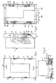
- the oscillating-wing bearing with two parallel bearing axes is of a known type and consists essentially of the wing Bearing part 1, the frame bearing part 2 and the intermediate bearing part 3 connected between the two.
- the first axis of rotation is designated by 4 and the second by 5.
- the surface of the swinging wing bearing (Fig. 1) facing the interior is covered.
- the intermediate bearing part 3 can carry a cover plate, both of which are firmly connected to one another.
- a first cover shell 6 is attached to the wing bearing part 1 and a second cover shell 7 is attached to the frame bearing part 2.
- the term "shell” is to be understood in the broadest sense, ie, contrary to the exemplary embodiment, it can also be a flat plate that forms a "casing".
- each cover shell carries at least one, but preferably two spaced-apart, inwardly projecting coupling projections 10 and 11 or 12 and 13. They are each molded onto the cover shell.
- Each has a coupling slot 14 which is open at the edge, the open slot end pointing away from the inner surface of the cover shell, as can be seen particularly well from FIG. 2 of the drawing.
- the coupling slot 14 receives an area 15 of an adjusting screw 16 with a reduced cross section, the shaft or at least the inner end of which carries a bolt thread 17.
- the lateral vertical edges 20, 21; 22, 23 of the cover shells 6 and 7 are angled or bent over, as a result of which they cover the heads "or outer ends of the adjusting screws 16. In order to be able to turn the adjusting screws anyway, there is an opening 24 at the appropriate place.
- the cover shells also overlap their bearing part 1 or 2 upwards or downwards. This can be seen particularly well from FIG. 3.
- the protruding edge area is there with 25 or 26 designated.
- a pocket-shaped receptacle is created for the alternating profile end.
- the interchangeable profiles on the sash and window frame can be cut off with a straight cut at 90 ° to the visible surface.
- a sealing plate can be inserted between the end of the interchangeable profile and the transverse wall 27 or 28 in a manner not shown.
- Each cover shell 6, 7 is connected to its associated bearing part 1, 2 via at least one, but preferably via at least two coupling devices 31 each. These are designed so that they allow the limited relative movement in the sense of the double arrows 8 and 9.
- Essential elements of the coupling device are a bolt 32 or the like and an extension 33 with an elongated hole which extends in the direction of displacement 8 and 9, respectively.
- the bolt is preferably a rivet or rivet attachment of the bearing shell in question, which has a thickened head 34 (FIG. 3) or is shaped therefor.
- the rivet connection is such that the relative movement between the bearing part and the cover shell is possible.
- the elongated hole is located on an extension 33, which consists of a strip, in particular a molded strip of the bearing part (FIG. 3).
- FIG. 4 shows that the bolt 32 on the cover shell is integrally formed and stepped, the part with a thinner cross section penetrating the bore of the washer 35.
- this refers to the bolt cross section in the bore of the washer 35.
Landscapes
- Engineering & Computer Science (AREA)
- Mechanical Engineering (AREA)
- Hinges (AREA)
- Axle Suspensions And Sidecars For Cycles (AREA)
- Support Of The Bearing (AREA)
- Rear-View Mirror Devices That Are Mounted On The Exterior Of The Vehicle (AREA)
- Chairs Characterized By Structure (AREA)
- Forklifts And Lifting Vehicles (AREA)
Priority Applications (1)
| Application Number | Priority Date | Filing Date | Title |
|---|---|---|---|
| AT87110977T ATE57230T1 (de) | 1986-08-30 | 1987-07-29 | Schwingfluegellager. |
Applications Claiming Priority (2)
| Application Number | Priority Date | Filing Date | Title |
|---|---|---|---|
| DE8623327U | 1986-08-30 | ||
| DE8623327U DE8623327U1 (de) | 1986-08-30 | 1986-08-30 | Schwingflügellager |
Publications (3)
| Publication Number | Publication Date |
|---|---|
| EP0258633A2 true EP0258633A2 (fr) | 1988-03-09 |
| EP0258633A3 EP0258633A3 (en) | 1988-07-20 |
| EP0258633B1 EP0258633B1 (fr) | 1990-10-03 |
Family
ID=6797868
Family Applications (1)
| Application Number | Title | Priority Date | Filing Date |
|---|---|---|---|
| EP87110977A Expired - Lifetime EP0258633B1 (fr) | 1986-08-30 | 1987-07-29 | Pivot pour panneau basculant |
Country Status (3)
| Country | Link |
|---|---|
| EP (1) | EP0258633B1 (fr) |
| AT (1) | ATE57230T1 (fr) |
| DE (2) | DE8623327U1 (fr) |
Family Cites Families (2)
| Publication number | Priority date | Publication date | Assignee | Title |
|---|---|---|---|---|
| CH266046A (de) * | 1946-08-31 | 1950-01-15 | Fritz Blaser & Cie Aktiengesel | Schwingflügellager. |
| DE1708413A1 (de) * | 1967-09-18 | 1971-05-13 | Hautau Baubeschlag | Lager fuer ueber zwei verschiedene Schwenkachsen bis zu 180 deg. schwenkbare Schwing- oder Wendefluegel |
-
1986
- 1986-08-30 DE DE8623327U patent/DE8623327U1/de not_active Expired
-
1987
- 1987-07-29 AT AT87110977T patent/ATE57230T1/de not_active IP Right Cessation
- 1987-07-29 DE DE8787110977T patent/DE3765367D1/de not_active Expired - Lifetime
- 1987-07-29 EP EP87110977A patent/EP0258633B1/fr not_active Expired - Lifetime
Also Published As
| Publication number | Publication date |
|---|---|
| DE3765367D1 (de) | 1990-11-08 |
| DE8623327U1 (de) | 1986-10-23 |
| ATE57230T1 (de) | 1990-10-15 |
| EP0258633A3 (en) | 1988-07-20 |
| EP0258633B1 (fr) | 1990-10-03 |
Similar Documents
| Publication | Publication Date | Title |
|---|---|---|
| DE3045233C2 (fr) | ||
| DE3872442T2 (de) | Drehbeschlag eines drehkippfluegels einer tuer eines fensters oder von aehnlichem. | |
| DE2739417C2 (de) | Möbelscharnier, insbesondere für Glastüren | |
| DE2741408A1 (de) | Beschlagsbaugruppe fuer fenster, tueren o.dgl. | |
| AT521814B1 (de) | Möbelscharnier | |
| CH645155A5 (de) | Tuerband. | |
| EP3425155B1 (fr) | Dispositif de protection anti-pince doigt pour une porte | |
| EP0292665A2 (fr) | Espagnolette pour portes, fenêtres ou similaires | |
| EP0258633B1 (fr) | Pivot pour panneau basculant | |
| DE4029694A1 (de) | Griff fuer eine kraftfahrzeugtuer | |
| DE8003712U1 (de) | Fenster oder tuer | |
| EP0620351A1 (fr) | Ferme porte | |
| DE20212055U1 (de) | Bandteil für ein Band für Türen, Fenster u.dgl. | |
| DE8812891U1 (de) | Verschlußvorrichtung für Fenster und Türen, insbesondere für Oberlichter | |
| DE2064047A1 (de) | Vorrichtung zur Feineinstellung von Dreh Kipp Fenstern | |
| EP0258639B1 (fr) | Palier rotatif avec dispositif de freinage pour un panneau de fenêtre, porte ou similaire | |
| EP3095937B1 (fr) | Raccordement de vantail de porte mobile | |
| DE8111079U1 (de) | Ecklager fuer fluegel von fenstern, tueren od. dgl. | |
| DE1908478B2 (de) | Treibstangenverbindung | |
| DE3034619A1 (de) | Ecklager fuer dreh-kipp-fenster, -tueren o.dgl. | |
| EP1582671B1 (fr) | Dispositif de monoeuvre pour battants de fenêtres ou de portes | |
| DE20304483U1 (de) | Band für Türen, Fenster o.dgl. | |
| DE2404812A1 (de) | Schieberlueftung, insbesondere fuer tueren, fenster und dgl. | |
| DE19743772B4 (de) | Ausstellvorrichtung mit Haltekörper | |
| EP0704593A1 (fr) | Ferrure pour battant pivotant, ou pivotant et basculant, de fenêtres, portes ou similaires avec pièce excentrique verrouillable pour regler la feuillure verticale et/ou la force de pression entre le vantail et le cadre fixe |
Legal Events
| Date | Code | Title | Description |
|---|---|---|---|
| PUAI | Public reference made under article 153(3) epc to a published international application that has entered the european phase |
Free format text: ORIGINAL CODE: 0009012 |
|
| AK | Designated contracting states |
Kind code of ref document: A2 Designated state(s): AT DE FR |
|
| PUAL | Search report despatched |
Free format text: ORIGINAL CODE: 0009013 |
|
| AK | Designated contracting states |
Kind code of ref document: A3 Designated state(s): AT DE FR |
|
| 17P | Request for examination filed |
Effective date: 19880622 |
|
| 17Q | First examination report despatched |
Effective date: 19900228 |
|
| GRAA | (expected) grant |
Free format text: ORIGINAL CODE: 0009210 |
|
| AK | Designated contracting states |
Kind code of ref document: B1 Designated state(s): AT DE FR |
|
| REF | Corresponds to: |
Ref document number: 57230 Country of ref document: AT Date of ref document: 19901015 Kind code of ref document: T |
|
| REF | Corresponds to: |
Ref document number: 3765367 Country of ref document: DE Date of ref document: 19901108 |
|
| ET | Fr: translation filed | ||
| PLBE | No opposition filed within time limit |
Free format text: ORIGINAL CODE: 0009261 |
|
| STAA | Information on the status of an ep patent application or granted ep patent |
Free format text: STATUS: NO OPPOSITION FILED WITHIN TIME LIMIT |
|
| 26N | No opposition filed | ||
| PGFP | Annual fee paid to national office [announced via postgrant information from national office to epo] |
Ref country code: AT Payment date: 19940628 Year of fee payment: 8 |
|
| PG25 | Lapsed in a contracting state [announced via postgrant information from national office to epo] |
Ref country code: AT Effective date: 19950729 |
|
| PGFP | Annual fee paid to national office [announced via postgrant information from national office to epo] |
Ref country code: DE Payment date: 19960517 Year of fee payment: 10 |
|
| PGFP | Annual fee paid to national office [announced via postgrant information from national office to epo] |
Ref country code: FR Payment date: 19960617 Year of fee payment: 10 |
|
| PG25 | Lapsed in a contracting state [announced via postgrant information from national office to epo] |
Ref country code: FR Free format text: LAPSE BECAUSE OF NON-PAYMENT OF DUE FEES Effective date: 19980331 |
|
| PG25 | Lapsed in a contracting state [announced via postgrant information from national office to epo] |
Ref country code: DE Free format text: LAPSE BECAUSE OF NON-PAYMENT OF DUE FEES Effective date: 19980401 |
|
| REG | Reference to a national code |
Ref country code: FR Ref legal event code: ST |