EP0258664A2 - Unité pour fixer des lignes électriques dans des distributeurs d'installations de télécommunication - Google Patents
Unité pour fixer des lignes électriques dans des distributeurs d'installations de télécommunication Download PDFInfo
- Publication number
- EP0258664A2 EP0258664A2 EP87111273A EP87111273A EP0258664A2 EP 0258664 A2 EP0258664 A2 EP 0258664A2 EP 87111273 A EP87111273 A EP 87111273A EP 87111273 A EP87111273 A EP 87111273A EP 0258664 A2 EP0258664 A2 EP 0258664A2
- Authority
- EP
- European Patent Office
- Prior art keywords
- contact
- fuses
- fuse
- assembly
- current
- Prior art date
- Legal status (The legal status is an assumption and is not a legal conclusion. Google has not performed a legal analysis and makes no representation as to the accuracy of the status listed.)
- Withdrawn
Links
- 238000009434 installation Methods 0.000 title 1
- 239000002184 metal Substances 0.000 claims abstract description 7
- 239000004020 conductor Substances 0.000 claims description 15
- 238000005452 bending Methods 0.000 claims description 9
- 238000001746 injection moulding Methods 0.000 claims description 7
- 238000005476 soldering Methods 0.000 claims description 3
- 230000013011 mating Effects 0.000 claims 1
- 238000011161 development Methods 0.000 description 12
- 230000018109 developmental process Effects 0.000 description 12
- 239000000463 material Substances 0.000 description 4
- 229910000679 solder Inorganic materials 0.000 description 4
- 238000004519 manufacturing process Methods 0.000 description 3
- 230000008018 melting Effects 0.000 description 2
- 238000002844 melting Methods 0.000 description 2
- 230000009286 beneficial effect Effects 0.000 description 1
- 238000006073 displacement reaction Methods 0.000 description 1
- 230000001771 impaired effect Effects 0.000 description 1
- 238000009413 insulation Methods 0.000 description 1
- 230000002035 prolonged effect Effects 0.000 description 1
- 238000004080 punching Methods 0.000 description 1
- 230000000284 resting effect Effects 0.000 description 1
- 230000035939 shock Effects 0.000 description 1
Images

Classifications
-
- H—ELECTRICITY
- H01—ELECTRIC ELEMENTS
- H01H—ELECTRIC SWITCHES; RELAYS; SELECTORS; EMERGENCY PROTECTIVE DEVICES
- H01H85/00—Protective devices in which the current flows through a part of fusible material and this current is interrupted by displacement of the fusible material when this current becomes excessive
- H01H85/02—Details
- H01H85/04—Fuses, i.e. expendable parts of the protective device, e.g. cartridges
- H01H85/041—Fuses, i.e. expendable parts of the protective device, e.g. cartridges characterised by the type
- H01H85/046—Fuses formed as printed circuits
-
- H—ELECTRICITY
- H01—ELECTRIC ELEMENTS
- H01T—SPARK GAPS; OVERVOLTAGE ARRESTERS USING SPARK GAPS; SPARKING PLUGS; CORONA DEVICES; GENERATING IONS TO BE INTRODUCED INTO NON-ENCLOSED GASES
- H01T4/00—Overvoltage arresters using spark gaps
- H01T4/06—Mounting arrangements for a plurality of overvoltage arresters
-
- H—ELECTRICITY
- H01—ELECTRIC ELEMENTS
- H01H—ELECTRIC SWITCHES; RELAYS; SELECTORS; EMERGENCY PROTECTIVE DEVICES
- H01H85/00—Protective devices in which the current flows through a part of fusible material and this current is interrupted by displacement of the fusible material when this current becomes excessive
- H01H85/02—Details
- H01H85/20—Bases for supporting the fuse; Separate parts thereof
- H01H2085/2085—Holders for mounting a fuse on a printed circuit
-
- H—ELECTRICITY
- H01—ELECTRIC ELEMENTS
- H01H—ELECTRIC SWITCHES; RELAYS; SELECTORS; EMERGENCY PROTECTIVE DEVICES
- H01H85/00—Protective devices in which the current flows through a part of fusible material and this current is interrupted by displacement of the fusible material when this current becomes excessive
- H01H85/02—Details
- H01H85/04—Fuses, i.e. expendable parts of the protective device, e.g. cartridges
- H01H85/041—Fuses, i.e. expendable parts of the protective device, e.g. cartridges characterised by the type
- H01H85/044—General constructions or structure of low voltage fuses, i.e. below 1000 V, or of fuses where the applicable voltage is not specified
-
- H—ELECTRICITY
- H01—ELECTRIC ELEMENTS
- H01H—ELECTRIC SWITCHES; RELAYS; SELECTORS; EMERGENCY PROTECTIVE DEVICES
- H01H85/00—Protective devices in which the current flows through a part of fusible material and this current is interrupted by displacement of the fusible material when this current becomes excessive
- H01H85/02—Details
- H01H85/44—Structural association with a spark-gap arrester
Definitions
- the invention relates to an assembly for securing electrical lines in distributors of telecommunications, in particular telephone systems.
- Such a flat assembly is known from DE-PS 3212013.
- the assembly is then fitted with power fuses strung together as a series link and can be connected to plug contacts of a layer module in a distributor of a telephone system.
- External lines leading to the subscribers and internal lines leading to the switching devices are connected to insulation displacement connectors of the layer modules connected to the plug contacts.
- the tubular fuses extend across the row direction of the fuses. These are held at their ends with their poles between bent legs of contact parts, which extend from the poles on both sides of a support part of the assembly to the plug contacts.
- the spring legs are bent out of the contact parts around a bending edge lying in the longitudinal direction of the fuse.
- the contact parts in the flat state in the region of the spring legs have a width which is greater than the spacing between the fuses.
- the pitch of the contact parts is considerably larger than that of the assembly.
- the sheet metal consumption is correspondingly large and the finished bent contact parts must be z. B. be connected by injection molding.
- the invention has for its object to enable a material and time-saving attachment of the contact parts.
- the handling of the contact parts is now no wider than in the clamping area.
- the pitch between the fuses is based on the thickness of the fuses at the poles, the width of the spring legs, and the minimum distance between the contact parts. Since the fuses on the poles are relatively thin, the pitch can be reduced so that the overall width of the layer module with the assembly is smaller.
- the contact parts each extend with the same sections in one plane, so that they can be used together in a strip held by connecting webs in the carrier part. Then the connecting webs z. B. cut by punching and the contact parts galvanically isolated.
- the power fuses can e.g. B. be formed as a flat circuit board or as a tubular elements, the poles of z. B. are flattened by squeezing.
- the contact parts are flat in the area of the fuses. Their shape results from a simple stamping contour that is created in one step. Such contact parts are much more dimensionally stable than curved parts, which also require a higher manufacturing effort.
- the training according to claim 2 results in extremely simple contact parts.
- the carrier part is designed as a simple, inexpensive to produce, double-sided laminated circuit board.
- the contact parts can be used in plated-through pads on the circuit board and with this z. B. connected by wave soldering.
- the contact parts are simultaneously formed as connecting parts to the plug contacts of the layer module.
- the base of the fork-shaped contact part can be laid in the flat area, so that the fuse is closer to the carrier part can be set. This makes it possible to reduce the height of the finished assembly.
- the development according to claim 5 makes it possible to sort the individual fuses according to their resistance and to insert two identical fuses into the housing.
- both conductor tracks can be finely etched in one operation under the same conditions, so that the line symmetry is not impaired.
- the fuse wires according to claim 8 can be obtained from two immediately successive sections of a long wire. These two sections are largely of the same nature, which is beneficial to the line affects symmetry.
- the safety wire is also suitable for flattening steep shock waves due to its inductance.
- the development according to claim 9 makes it possible to arrange two separate connections at each end of the base part.
- the development according to claim 11 is based on an assembly according to DE-PS 25 08 845.
- the assembly is then provided with a carrier part produced by injection molding with embedded contact pieces which are provided along a longitudinal edge of the carrier part with contact surfaces for plug contacts of the layer modules.
- the contact pieces are provided with contact zones lying in the plane of the support part for fusible pieces resting on the surge arresters. With their central axis, the surge arresters are perpendicular to the support part.
- a grounding multiple which is U-shaped in cross-section and is made of sheet metal and which rests with spring fingers on the poles of the surge arresters facing away from the carrier part.
- the contact pieces have a U-shaped section which projects into the vicinity of the free ends of the spring fingers. This section lies between the surge arresters and the contact areas. The distance between the bent sections and the spring fingers is less than the thickness of the melting pieces. In the event of a prolonged overload, these melt, so that the contact piece is short-circuited to earth.
- Such a U-shaped bend requires a space corresponding to the distance between the legs.
- a sufficient contact length for the bending tools must be on both sides of the legs be provided.
- the height of the bend can only be formed with a low degree of accuracy, since with such a multiple bend a considerable springback must be expected, which fluctuates depending on the material thickness and the material properties. This changes the distance to the spring fingers of the grounding multiple, so that the exact coordination is not guaranteed with complete certainty.
- the further development according to claim 11 improves the manufacturability and functional reliability of the assembly.
- the section bent up as a simple tab has only one bend which can be produced with a simple tool.
- the contact surface with the spring fingers is the punched-out end face of the contact tab. In the flat state, the position of this end face can be determined with high precision.
- the strip-shaped contact tab can be largely embedded in the carrier part by injection molding, so that its position is reliably stabilized.
- the contact tab can be bent up very close to the surge arrester, which saves considerable space.
- the length and width of the unbent contact piece can be kept small.
- the contact tab can be arranged on the side of the surge arrester facing away from the rear. The earthing multiple points with its earthing fingers in this direction, so that it can be designed as a U-shaped sheet metal part that clasps the back of the assembly.
- the development according to claim 13 results in a space-saving shape of the contact pieces. This makes it possible to provide the module with additional power fuses.
- DE-PS 32 12 013 the bending axes for the contact parts parallel to the longitudinal direction of the contact pieces, so that they have a greater width when unbent.
- the contact part for the power fuse and the contact tab can be closely adjacent, which results in a particularly space-saving arrangement.
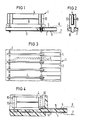
- an assembly 1 consists of a double-sided printed circuit board 2 with contact parts 3 and power fuses 4th
- the printed circuit board 2 has along a longitudinal edge perpendicular to this contact surface 5, which are contacted with plug contacts 6 of a layer module of a distributor in a telephone exchange.
- the plug contacts 6 are each formed on an external contact spring 7 and an internal contact spring 8 of a layer component of a distributor in a telephone exchange.
- the external contact springs 7 are connected to the subscriber lines leading outwards and the internal contact springs 8 are connected to the lines leading inwards to the switching system.
- the external and internal contact springs 7 and 8 are connected in pairs to one another via the contact surface 5, conductor tracks 9, the contact parts 3 and the current fuses 4.
- the current fuses 4 are designed as elongated, flat fuse plates which are perpendicular to the printed circuit board 2 over their longitudinal edge. They extend just like the conductor tracks 9 perpendicular to the longitudinal edge of the assembly 1 and are lined up parallel to one another.
- the current fuses 4 are designed as printed circuit boards, at the ends of which the poles 10 are designed as flat contact zones which are connected to one another via a finely etched thin fuse track 11.
- the contact parts 3 are inserted with a soldering mandrel 12 into pressure-contacted solder pads connected to the conductor tracks 9 and are soldered therein. They are designed as flat plates, from which a central longitudinal slot open to their free end is punched out. Spring legs 13 are thus formed on both sides of this longitudinal slot and clamp the current fuses 4 in a resilient manner. They are contacted with the poles of the power fuses 4.
- FIG. 4 other contact parts 14 are formed in their contact area to the power fuses 4 similar to the contact parts 3 according to FIG. 2.
- the printed circuit board 2 is replaced by a carrier part 15 which is produced by injection molding and into which the contact parts 14 are embedded.
- These form the contact surfaces 5 for the plug contacts 6 of the external and internal contact springs 7 and 8 at one end and have the spring legs 13 at their other end. From the contact surfaces 5, the contact parts 14 are guided flat on the carrier part 15 to below the poles 10 of the current fuses 4 and are bent there at right angles to them.
- the spring legs 13 are attached directly above the carrier part 15, so that the current fuse 4 is at a short distance from the carrier part 15.
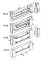
- a simple current fuse 21 consists of a plate-shaped base part 22, contact surfaces 23 at both ends of the base part 22 and a thin etched conductor track 24 which connects the two contact surfaces 23 to one another.
- two current fuses 21 with the same electrical properties are inserted in the arrow direction in receiving openings 25 of a housing 26 and held clamped therein.
- the housing 26 is shorter than the power fuses 21, so that the contact surfaces 23 can protrude on both sides when inserted.
- the two current fuses 21 held in the housing 26 can be inserted with their two ends between fork-like spring contacts 17 of an electrical assembly 28.
- the spring contacts 27 are connected to electrical conductor tracks of the assembly 28.
- the conductor tracks lead to plug contact points, not shown, which can be connected to contact springs of the distributor connected to the wires of the subscriber lines.
- the two power fuses are to a double power fuse 29 on a common base part summarized.
- the double current fuse 29 has a total of four contact surfaces 23 at both ends on both sides. Two of the contact surfaces 23 at one end are connected to one another via a plated-through solder pad 31 and a thin etched, loop-shaped conductor track 24. The two conductor tracks 24 are arranged next to one another on the same side of the base part 30.
- the current fuse 29 can be inserted with its contact surfaces 23 between galvanically isolated legs 32 from other spring contacts 33. When the power fuse 29 is removed, the legs 32 lie directly against one another with their contact points, so that the electrical connection is maintained even when the power fuse is pulled out.
- another double current fuse 34 is provided with fuse wires 35 instead of the conductor tracks 24 (FIG. 3). These are laid from a contact surface 23 in a loop on one side of the base part 30 and guided through a bore 36 to the other contact surface 23 located at the same end.
- the securing wires 35 are soldered to solder eyes 37 at both ends, which are connected to the contact surfaces 23.
- the fuse wires 35 are laid in a straight line between the two ends on one side of the base part 30.
- the pads 37 are arranged on the same side for both safety wires 15.
- one of the pairs of solder eyes 37 is plated through to the other side and is connected there to the opposite contact surfaces 23. Since the two contact surfaces 23 are each assigned to different cable runs at one end, the associated spring contacts 33 are also open in the unassembled state.
- FIG. 10 another simple current fuse 38 similar to FIG. 5 is provided with a fuse wire 35 instead of the etched conductor track.
- This current fuse can also be inserted into a housing 26 (FIG. 5).
- the housing protects the actual fuse and prevents the fuse from burning tion path that the arc can escape or remains for a long time because the plastic evaporates and extinguishes.
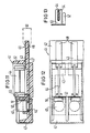
- an assembly 41 consists of a carrier part 42 made of injection molding, contact pieces 43, current fuses 44, surge arresters 45, fusible links 46 and an earthing multiple 47.
- the contact pieces 43 are provided along a longitudinal edge of the carrier part 42 with contact surfaces 48 for plug contacts 49 of contact springs 50 of a layer module, which is arranged in a layer distributor of a telephone switching system.
- the contact pieces 43 are embedded in the carrier part by injection molding and extend essentially perpendicular to the row direction in the plane of the carrier part 42.
- a short contact piece 43 is fork-shaped with its vertically bent free end and engages around a pole of the current fuse 44. The longer one above the other lying contact pieces 43 extend from the contact surfaces 48 to the rear of the carrier part 42, where it forms a contact zone for the melting piece 46.
- the surge arrester 45 is placed, which rests with its other pole on a spring finger 51 of the U-shaped earthing multiple 47 bent from sheet metal.
- a free-punched contact tab 52 is bent out of the longer contact part 43 and projects with its free end into the vicinity of the spring finger 51 and is largely enveloped by the carrier part 42.
- the bending edge lies in the longitudinal direction of the assembly 41.
- the contact tab 52 points in the direction of the contact surface 48 before bending up.
- the long contact piece 43 is in the immediate vicinity of the contact tab 52, another tab in the form of a contact part 53 for the other pole of the power fuse 44 bent out in a similar manner to the contact tab 52.
- the current fuse 44 thus establishes the electrical connection between the two contact pieces 43 and thus between the two contact springs 50.
- the contact part 53 for the power fuse 44 is designed as a flat fork, the material plane of which extends in the longitudinal direction of the assembly.
- the plate-like current fuse 44 is clamped between two side legs of the contact part 53 and contacted.
Landscapes
- Fuses (AREA)
- Details Of Connecting Devices For Male And Female Coupling (AREA)
- Communication Cables (AREA)
- Insulated Conductors (AREA)
- Details Of Indoor Wiring (AREA)
Applications Claiming Priority (6)
| Application Number | Priority Date | Filing Date | Title |
|---|---|---|---|
| DE3628806 | 1986-08-25 | ||
| DE3628841 | 1986-08-25 | ||
| DE3628806 | 1986-08-25 | ||
| DE3628804 | 1986-08-25 | ||
| DE3628804 | 1986-08-25 | ||
| DE3628841 | 1986-08-25 |
Publications (2)
| Publication Number | Publication Date |
|---|---|
| EP0258664A2 true EP0258664A2 (fr) | 1988-03-09 |
| EP0258664A3 EP0258664A3 (fr) | 1990-03-21 |
Family
ID=27194761
Family Applications (1)
| Application Number | Title | Priority Date | Filing Date |
|---|---|---|---|
| EP87111273A Withdrawn EP0258664A3 (fr) | 1986-08-25 | 1987-08-04 | Unité pour fixer des lignes électriques dans des distributeurs d'installations de télécommunication |
Country Status (4)
| Country | Link |
|---|---|
| EP (1) | EP0258664A3 (fr) |
| AU (1) | AU598849B2 (fr) |
| FI (1) | FI873656L (fr) |
| NO (1) | NO873577L (fr) |
Cited By (4)
| Publication number | Priority date | Publication date | Assignee | Title |
|---|---|---|---|---|
| EP1710825A3 (fr) * | 2005-04-04 | 2007-10-24 | Patent-Treuhand-Gesellschaft für elektrische Glühlampen mbH | Ensemble de fusibles pour protéger un appareil électrique contre les surintensités |
| EP1990818A3 (fr) * | 2007-05-10 | 2009-12-09 | Delphi Technologies, Inc. | Système et procédé pour l'interconnexion d'une pluralité de circuits imprimés |
| WO2018144475A1 (fr) * | 2017-01-31 | 2018-08-09 | Continental Automotive Systems, Inc. | Système de fusible à lame en ligne |
| CN112956068A (zh) * | 2018-11-16 | 2021-06-11 | 日本汽车能源株式会社 | 电池模块 |
Families Citing this family (3)
| Publication number | Priority date | Publication date | Assignee | Title |
|---|---|---|---|---|
| EP0258629A3 (fr) * | 1986-08-25 | 1990-01-31 | Siemens Aktiengesellschaft | Module pour protéger les lignes électriques dans des installations de télécommunication |
| ATE112095T1 (de) * | 1986-08-25 | 1994-10-15 | Siemens Ag | Baugruppe zum sichern von elektrischen leitungen in verteilern von telekommunikationsanlagen. |
| NZ234141A (en) * | 1989-06-28 | 1992-10-28 | Siemens Ag | Safety connector to distribution frame for voltage surge protectors |
Family Cites Families (9)
| Publication number | Priority date | Publication date | Assignee | Title |
|---|---|---|---|---|
| DE1249935B (fr) * | 1962-07-24 | 1967-09-14 | ||
| DE2508845C3 (de) * | 1975-02-28 | 1980-10-02 | Siemens Ag, 1000 Berlin Und 8000 Muenchen | Sicherungsleiste |
| DE2720220A1 (de) * | 1977-05-05 | 1978-11-16 | Siemens Ag | Sicherungsleiste zur halterung elektrischer sicherungen |
| DE3024864A1 (de) * | 1980-07-01 | 1982-01-21 | Licentia Patent-Verwaltungs-Gmbh, 6000 Frankfurt | Haltevorrichtung fuer knopfableiter |
| DE3212013C2 (de) * | 1982-03-31 | 1984-08-09 | Siemens AG, 1000 Berlin und 8000 München | Trennvorrichtung für Verteileranlagen |
| JPS58176392U (ja) * | 1982-05-20 | 1983-11-25 | 株式会社サンコ−シャ | アレスタ保持装置 |
| EP0254126A3 (fr) * | 1986-07-24 | 1989-03-29 | Siemens Aktiengesellschaft | Structure enfichable avec fusibles pour répartiteur |
| EP0258629A3 (fr) * | 1986-08-25 | 1990-01-31 | Siemens Aktiengesellschaft | Module pour protéger les lignes électriques dans des installations de télécommunication |
| ATE112095T1 (de) * | 1986-08-25 | 1994-10-15 | Siemens Ag | Baugruppe zum sichern von elektrischen leitungen in verteilern von telekommunikationsanlagen. |
-
1987
- 1987-08-04 EP EP87111273A patent/EP0258664A3/fr not_active Withdrawn
- 1987-08-24 FI FI873656A patent/FI873656L/fi not_active Application Discontinuation
- 1987-08-24 AU AU77353/87A patent/AU598849B2/en not_active Ceased
- 1987-08-25 NO NO873577A patent/NO873577L/no unknown
Cited By (5)
| Publication number | Priority date | Publication date | Assignee | Title |
|---|---|---|---|---|
| EP1710825A3 (fr) * | 2005-04-04 | 2007-10-24 | Patent-Treuhand-Gesellschaft für elektrische Glühlampen mbH | Ensemble de fusibles pour protéger un appareil électrique contre les surintensités |
| EP1990818A3 (fr) * | 2007-05-10 | 2009-12-09 | Delphi Technologies, Inc. | Système et procédé pour l'interconnexion d'une pluralité de circuits imprimés |
| US7701321B2 (en) | 2007-05-10 | 2010-04-20 | Delphi Technologies, Inc. | System and method for interconnecting a plurality of printed circuits |
| WO2018144475A1 (fr) * | 2017-01-31 | 2018-08-09 | Continental Automotive Systems, Inc. | Système de fusible à lame en ligne |
| CN112956068A (zh) * | 2018-11-16 | 2021-06-11 | 日本汽车能源株式会社 | 电池模块 |
Also Published As
| Publication number | Publication date |
|---|---|
| NO873577D0 (no) | 1987-08-25 |
| FI873656A7 (fi) | 1988-02-26 |
| FI873656L (fi) | 1988-02-26 |
| NO873577L (no) | 1988-02-26 |
| EP0258664A3 (fr) | 1990-03-21 |
| AU7735387A (en) | 1988-02-25 |
| FI873656A0 (fi) | 1987-08-24 |
| AU598849B2 (en) | 1990-07-05 |
Similar Documents
| Publication | Publication Date | Title |
|---|---|---|
| DE3137429C2 (de) | Anschlußeinrichtung in einer Anschlußleiste | |
| EP0634888B1 (fr) | Unité enfichable, en particulier module de relais pour véhicules automobiles | |
| DE3850167T2 (de) | Elektrische Verbinderklemme für biegsame gedruckte Leiterplatte. | |
| DE4017423C2 (fr) | ||
| DE2525641A1 (de) | Vorrichtung zum gleichzeitigen einsetzen jedes leitungsdrahts von zwei elektrischen leitungsdrahtgruppen in einen schlitz eines einzelnen elektrischen kontakts eines elektrischen verbinders | |
| DE10317621B4 (de) | Überspannungsschutzmagazin für eine Einrichtung der Telekommunikationstechnik | |
| DE68911827T2 (de) | Verbinder. | |
| DE1615666C3 (de) | Elektrische Klemmhülse | |
| DE2815634C2 (de) | Elektrisches Verbindungsstück | |
| EP0634813A2 (fr) | Bloc de distribution | |
| EP0856911A1 (fr) | Bloc de connexion multipolaire | |
| DE2603151C3 (de) | Bauelement für Schalt- und/oder Trennleisten in Verteilern für Fernmeldeanlagen | |
| DE1195385B (de) | Festklemmbares Kontaktstueck fuer Fernmelde-, insbesondere Fernsprechanlagen | |
| DE9415087U1 (de) | Steckbare elektrische Verbindungsvorrichtung | |
| EP0890205B1 (fr) | Dispositif de distribution d'un distributeur dans un systeme de telecommunications | |
| DE3625238C2 (fr) | ||
| EP0990280B1 (fr) | Connecteur de protection pour dispositif utilise dans la technique des telecommunications | |
| DE2617172A1 (de) | Anschlussblock fuer kabelenden, insbesondere fuer fernmeldekabel | |
| EP0258629A2 (fr) | Module pour protéger les lignes électriques dans des installations de télécommunication | |
| EP0258628B1 (fr) | Module pour protéger les lignes électriques dans des répartiteurs d'installations de télécommunication | |
| DE2056909B2 (de) | Verfahren zur Herstellung von kunststoffumhüllten Spulen | |
| EP1587166A1 (fr) | Bloc de répartition | |
| EP2425498B1 (fr) | Système de liaison pour une carte de circuit imprimé | |
| EP0234367B1 (fr) | Contact élastique pour bloc de connexion électrique | |
| DE3004874A1 (de) | Platine fuer elektrische geraete o.dgl. |
Legal Events
| Date | Code | Title | Description |
|---|---|---|---|
| PUAI | Public reference made under article 153(3) epc to a published international application that has entered the european phase |
Free format text: ORIGINAL CODE: 0009012 |
|
| AK | Designated contracting states |
Kind code of ref document: A2 Designated state(s): AT BE CH DE FR GB LI NL SE |
|
| PUAL | Search report despatched |
Free format text: ORIGINAL CODE: 0009013 |
|
| AK | Designated contracting states |
Kind code of ref document: A3 Designated state(s): AT BE CH DE FR GB LI NL SE |
|
| RHK1 | Main classification (correction) |
Ipc: H01T 4/06 |
|
| 17P | Request for examination filed |
Effective date: 19900425 |
|
| STAA | Information on the status of an ep patent application or granted ep patent |
Free format text: STATUS: THE APPLICATION IS DEEMED TO BE WITHDRAWN |
|
| 18D | Application deemed to be withdrawn |
Effective date: 19910301 |
|
| RIN1 | Information on inventor provided before grant (corrected) |
Inventor name: RUDOLF, HANS-WERNER, DR.RER.NAT. Inventor name: STEINER, EWALD, ING. Inventor name: SCHOLTHOLT, HANS, ING. |