EP0258884A1 - Scheidungs- und Konzentrierungsmethode einer organischen Verbindung aus einer wässerigen Lösung, die diese enthält - Google Patents
Scheidungs- und Konzentrierungsmethode einer organischen Verbindung aus einer wässerigen Lösung, die diese enthält Download PDFInfo
- Publication number
- EP0258884A1 EP0258884A1 EP87112810A EP87112810A EP0258884A1 EP 0258884 A1 EP0258884 A1 EP 0258884A1 EP 87112810 A EP87112810 A EP 87112810A EP 87112810 A EP87112810 A EP 87112810A EP 0258884 A1 EP0258884 A1 EP 0258884A1
- Authority
- EP
- European Patent Office
- Prior art keywords
- aqueous solution
- organic component
- boiling point
- membrane
- porous membrane
- Prior art date
- Legal status (The legal status is an assumption and is not a legal conclusion. Google has not performed a legal analysis and makes no representation as to the accuracy of the status listed.)
- Granted
Links
Images

Classifications
-
- B—PERFORMING OPERATIONS; TRANSPORTING
- B01—PHYSICAL OR CHEMICAL PROCESSES OR APPARATUS IN GENERAL
- B01D—SEPARATION
- B01D61/00—Processes of separation using semi-permeable membranes, e.g. dialysis, osmosis or ultrafiltration; Apparatus, accessories or auxiliary operations specially adapted therefor
- B01D61/36—Pervaporation; Membrane distillation; Liquid permeation
- B01D61/362—Pervaporation
-
- Y—GENERAL TAGGING OF NEW TECHNOLOGICAL DEVELOPMENTS; GENERAL TAGGING OF CROSS-SECTIONAL TECHNOLOGIES SPANNING OVER SEVERAL SECTIONS OF THE IPC; TECHNICAL SUBJECTS COVERED BY FORMER USPC CROSS-REFERENCE ART COLLECTIONS [XRACs] AND DIGESTS
- Y10—TECHNICAL SUBJECTS COVERED BY FORMER USPC
- Y10S—TECHNICAL SUBJECTS COVERED BY FORMER USPC CROSS-REFERENCE ART COLLECTIONS [XRACs] AND DIGESTS
- Y10S159/00—Concentrating evaporators
- Y10S159/27—Micropores
Definitions
- This invention relates to a method for efficiently separating and concentrating a useful organic component having a lower boiling point than water (hereinafter referred to as an organic component having a low boiling point) from an aqueous solution (such as a broth or the like) by the utilization of a hydrophobic porous membrane and a hydrophobic nonporous membrane.
- both water and the fermentation product having a low boiling point are separated from the fermentation system, so that the raw material for fermentation (such as glucose) and the inorganic salts also go out of the fermentation system.
- the fermentation product must subsequently be separated therefrom.
- the residue from which the fermentation product has been separated is discarded. This is not only disadvantageous from an economic point of view, but also poses a problem in that the raw material for fermentation and the inorganic salts must be supplied to the fermenter so as to make up for the loss.
- the present inventors carried out intensive research and found that a hydrophobic porous membrane allows the passage of vapors, but does not allow the passage of an organic material-containing aqueous solution in liquid form.
- the present inventor devised a method for separating and concentrating an organic component having a low boiling point from an aqueous solution containing organic components by bringing the aqueous solution containing organic components into contact with one surface of a hydrophobic porous membrane and evacuating the side of the porous membrane opposite to the aqueous solution, and disclosed it in the previous Japanese Patent Application No. 39408/'85.
- hydrophobic nonporous membranes are also known.
- silicone rubber is more permeable to the vapors of organic components having a low boiling point (such as ethanol and the like) than to water vapor, and thus makes it possible to concentrate such organic components having a low boiling point.
- organic components having a low boiling point such as ethanol and the like
- hydrophobic nonporous membranes are still disadvantageous in that they have a considerably lower permeability to vapors than porous membranes and, especially when the aqueous solution has a low organic component concentration, the above permeability is too low for practical purposes because the membrane does not swell so much due to the organic component.
- a method for separating and concentrating an organic component having a lower boiling point than water from an aqueous solution containing the organic component which comprises the steps of
- a concentrated vapor of an organic component having a low boiling point is obtained by bringing an aqueous solution containing the organic component having a low boiling point into contact with one surface of a hydrophobic porous membrane and evacuating the side of the hydrophobic porous membrane opposite to the aqueous solution.
- the hydrophobic porous membrane used in the method of the present invention should preferably have a bubble point of not less than 1 kg/cm2 and more preferably in the range of 2 to 20 kg/cm2. If the bubble point is above the aforesaid upper limit, the permeation rate of the organic component to be separated and concentrated will be undesirably low. If the bubble point is lower than the aforesaid lower limit, the aqueous solution in liquid form will tend to pass through the membrane with a lapse of time when the side of the membrane opposite to the aqueous solution is evacuated.
- the bubble point can be determined according to the procedure of ASTM F316-80.
- the bubble point can be determined as follows: A hollow fiber module including a bundle of hollow fibers arranged in a loop is prepared and immersed in ethanol. Using an aspirator, the ethanol is sucked in until the inside of the hollow fibers is fully wetted therewith. Then, the internal pressure of the hollow fibers is elevated in 0.1 kg/cm2 increments. The bubble point (in kg/cm2) is defined as the pressure at which bubbles begin to appear from almost all the outer surfaces of the hollow fibers.
- the porous membrane used in the method of the present invention preferably has a thickness of 10 to 100 ⁇ m and more preferably 20 to 60 ⁇ m. It also has a porosity of 20 to 80% and preferably 40 to 75%.
- the material of the membrane can be any of various materials, such as Teflon, polyolefins and the like, which are hydrophobic and can satisfy the aforesaid conditions. Even a membrane formed of a hydrophilic material can be used if its surfaces are rendered hydrophobic. Although flat membranes may be used, it is especially preferable to use hollow fibers for the purpose of reducing the size of the apparatus.
- the organic component having a low boiling point which can be separated and concentrated according to the method of the present invention may be any organic material characterized by the fact that, in the vapor-liquid equilibrium between the organic component having a low boiling point and water, the vapor phase contains the low-boiling organic material at a higher concentration than the liquid phase in equilibrium therewith.
- Typical examples of such organic materials include methanol, ethanol, butanol, acetone, tetrahydrofuran and triethylamine.
- the method of the present invention may be applied, for example, to the recovery of organic components having a low boiling point from waste liquids discharged from various processes. However, it is particularly suitable for the recovery of an organic component having a low boiling point from a broth and especially effective in the recovery of the fermentation product, for example, from an ethanol fermentation or an acetone-butanol fermentation.
- the opposite side In separating and concentrating the organic component by use of a hydrophobic porous membrane, it is essential to evacuate the side of the membrane opposite to the aqueous solution containing the organic component (that side of the membrane will hereinafter be referred to briefly as the "opposite side"). This evacuation may be carried out either continuously or intermittently.
- the reduced pressure level to which the opposite side is evacuated should conveniently be as low as possible, because this enhances the separation rate of the organic component having a low boiling point. In practice, however, the reduced pressure level may be properly determined on the basis of the bubble point of the membrane.
- the reduced pressure level is usually in the range of 0.1 to 500 mmHg and preferably in the range of 0.1 to 380 mmHg.
- this evacuation may be carried out simply by evacuating the aforesaid "opposite side” by means of a pump or the like, it is preferable to evacuate the "opposite side” while causing an inert gas to flow therethrough.
- the flow of the inert gas permits the organic component vapor staying around the membrane surface to be effectively removed, resulting in a further improvement in separation rate.
- the inert gas used for this purpose can be any gas that does not react with the organic component having a low boiling point, and preferred examples of such gases include air, nitrogen gas and carbon dioxide gas.
- the reduced pressure level to which the "opposite side” is evacuated may be the same as described above.
- the pressure to which the "opposite side” is pressurized should preferably be such that the inert gas or air bubbles in the aqueous solution.
- the pressure may preferably range from 150 to 760 mmHg gauge, depending on the pore size and wettability of the membrane.
- Below the aforesaid lower limit a reduction in the permeability of the membrane cannot be prevented satisfactorily.
- the pressurization cannot be expected to produce any additional effect in preventing a reduction in the permeability of the membrane.
- such excessive pressurization undesirably causes an increase in cost and, further, involves the risk of causing damage to the membrane.
- the duration of the pressurization should preferably be as short as possible. However, if it is too short, the pressurization may not be satisfactorily effective in preventing a reduction in the permeability of the membrane.
- the duration of the pressurization in each cycle may preferably range from one second to ten minutes.
- the interval of time between one pressurization period and the next may preferably range from one minute to one hour, depending on the type of the organic component having a low boiling point, the composition of the aqueous solution, the pore size of the porous membrane, and other factors.
- the resulting concentrated vapor mixture composed of the organic component having a low boiling point and water is then liquefied by introducing it into a suitable liquefaction means.
- a cold trap is usually used as the liquefaction means, it is also possible to use a barometric condenser.
- a further concentrated vapor of the organic component having a low boiling point is obtained by bringing the concentrated aqueous solution into contact with a hydrophobic nonporous membrane and evacuating the side of the membrane opposite to the concentrated aqueous solution in the second stage of the method of the present invention.
- the nonporous membrane used for this purpose should desirably as thin as possible, provided that its strength and separation properties are acceptable. In practice, nonporous membranes having a thickness of 80 ⁇ m or less are suitable for use in the method of the present invention.
- the material of the membrane can be any of various hydrophobic materials, and typical examples thereof include silicone rubber, polycarbonates, polyolefins, polyfluoroolefins and the like.
- the nonporous membrane may be in the form of a flat membrane, but it is preferable to use hollow fibers.
- the term "nonporous membrane” does not necessarily denote membranes consisting entirely of a nonporous material (i.e., homogeneous membranes), but can also comprehend composite membranes consisting of a nonporous membrane provided with a supporting or reinforcing porous membrane on one side or both sides.
- the resulting further concentrated vapor mixture of the organic component having a low boiling point and water may be recovered simply by evacuating the "opposite side” of the membrane.
- evacuate the "opposite side” of the membrane while causing an inert gas to flow therethrough as a carrier gas for the vapor mixture to be recovered.
- the inert gas used for this purpose may be the same as that which was caused to flow through the "opposite side" of the porous membrane.
- gases include air, nitrogen gas and carbon dioxide gas.
- the reduced pressure level to which the "opposite side” is evacuated should conveniently be as low as possible, because this enhances the separation rate of the organic component having a low boiling point. However, it usually suffices to evacuate the "opposite side” to a pressure in the range of 0.1 to 380 mmHg.
- the resulting further concentrated vapor mixture containing the low-boiling organic component at a higher concentration is then liquefied by introducing it into a suitable liquefaction means.
- a suitable liquefaction means such as a cold trap or a barometric condenser is used as the liquefaction means.
- a portion of the broth may be continuously withdrawn from the fermenter by means of a feed pump, passed through a separator-concentrator having a hydrophobic porous membrane incorporated therein to separate the fermentation product therefrom, and then returned to the fermenter.
- a separator-concentrator having a hydrophobic porous membrane incorporated therein to separate the fermentation product therefrom, and then returned to the fermenter.
- the separator-concentrator may be placed in the fermenter so as to bring the broth into contact with one surface of the membrane.
- this necessitates a suitable means for stirring the broth.
- Fig. 1 is a flow chart illustrating one embodiment of the method of the present invention
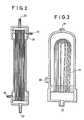
- Figs. 2 and 3 are schematic sectional views of hollow-fiber modules having hydrophobic porous hollow fibers or hydrophobic nonporous hollow fibers incorporated therein and being suitable for use as separator-concentrators.
- an aqueous solution containing an organic component having a low boiling point is placed in an aqueous solution tank 1.
- a circulating pump 2 By means of a circulating pump 2, the aqueous solution is transferred into a first-stage separator-concentrator 3 through its aqueous solution inlet 18. Then, the aqueous solution flows through the first-stage separator-concentrator 3 while keeping contact with the outer surfaces of porous hollow fibers 17. Thereafter, it is discharged from an aqueous solution outlet 19 and returned to the aqueous solution tank 1.
- the hollow fibers 17 have a porous structure pierced by minute openings, but are of a hydrophobic nature. Thus, the aqueous solution containing the organic component having a low boiling point cannot pass through the wall (or porous membrane) of the hollow fibers as long as it is in liquid form.
- the organic component having a low boiling point and water vaporize within the confines of the wall and the resulting vapors flow into the evacuated bores of the hollow fibers.
- the vapor-liquid equilibrium relationship between water and the organic component having a low boiling point causes the vapor mixture present in the bores of the hollow fibers to have a higher organic component concentration than the aqueous solution.
- a device as illustrated in Fig. 2 is used as the separator-concentrator and the bores of the hollow fibers are simply evacuated, the resulting vapor mixture emerges from its vapor outlet 21.
- a carrier gas such as nitrogen gas is passed through the bores of the hollow fibers by supplying it from a gas cylinder 12 by way of a flowmeter 13 and a carrier gas inlet 15 and sucking it from a vapor outlet 21 by means of a vacuum pump 11, the resulting vapor mixture, together with the carrier gas, emerges from the vapor outlet 21.
- This vapor mixture emerging from the vapor outlet 21 is liquefied in a cold trap 4 which has been cooled, for example, to -40°C.
- the resulting concentrated aqueous solution is then transferred to an intermediate tank 5.
- the concentrated aqueous solution is transferred into a second-stage separator-concentrator 7 through its aqueous solution inlet 18. Then, the concentrated aqueous solution flows through the second-stage separator-concentrator 7 while remaining in contact with the outer surfaces of hydrophobic nonporous hollow fibers 17. Thereafter, it is discharged from an aqueous solution outlet 19 and returned to the intermediate tank 5.
- the bores of the nonporous hollow fibers are evacuated, water and the organic component having a low boiling point permeate through the nonporous membrane and enter the bores of the hollow fibers.
- the vapor mixture obtained in the bores of the hollow fibers contains the low-boiling organic component at a still higher concentration.
- a carrier gas is supplied from the gas cylinder 12 by way of a flowmeter 14 and passed through the bores of the hydrophobic nonporous hollow fibers.
- the vapor mixture obtained in the bores of the nonporous hollow fibers, together with the carrier gas, is sucked out by means of the vacuum pump 11 and introduced into a second cold trap 8 kept at low temperature.
- the system illustrated in Fig. 1 further includes manometers 9 and 10 for measuring the reduced pressure level, an electromagnetic valve 15 for effecting changeover between pressurization and evacuation of the side of the hydrophobic porous membrane opposite to the aqueous solution fed to the first-stage separator-concentrator 3, and a timer 16 for presetting the intervals and durations of pressurization and evacuation.
- the first-stage separator-concentrator 3 it may happen that, in addition to vapors, liquid components leak in the bores of the hollow fibers for some reason or other. In such a case, the liquid recovered in the cold trap 4 will show a reduction in the concentration of the organic component having a low boiling point. Accordingly, it is preferable to provide a liquid trap (a room-temperature or warm trap) between the vapor outlet of the first-stage separator-concentrator 3 and the cold trap 4.
- a liquid trap a room-temperature or warm trap
- first-stage separator-concentrator only one first-stage separator-concentrator is included in the embodiment illustrated in Fig. 1. However, there may preferably be used any required number of first-stage separator-concentrators arranged in parallel, depending on the capacity of the second-stage separator-concentrator.
- the temperature of the fermenter may be different from that of the first-stage separator-concentrator, provided that the temperature difference exerts no influence on the activity of the yeast cells.
- the separation and concentration method of the present invention makes it possible to readily obtain a highly concentrated aqueous solution of an organic component having a low boiling point from an aqueous solution containing the organic component at a relatively low concentration. Moreover, even if an aqueous solution containing considerable amounts of impurities (such as a broth) is used as the starting solution, the resulting liquid concentrate is free from yeast cells, inorganic salts and raw materials (such as glucose and the like). Furthermore, the combined use of a hydrophobic porous membrane and a hydrophobic nonporous membrane enhances the permeation rate of vapors and permits more efficient operation, as compared with the prior art pervaporation method. In particular, the use of hollow fibers is advantageous in that the equipment can be made more compact.
- the side of the membrane opposite to the aqueous solution may be alternately evacuated and pressurized at predetermined intervals of time to clean the surface of the membrane and restore the hydrophobicity of the membrane.
- the method of the present invention is also advantageous in that organic components having a low boiling point and free from any other nonvolatile matter can be efficiently recovered from waste liquids containing the organic components having a low boiling point, such as waste liquids from various processes.
- This example illustrates a batch process in which the first-stage operation and the second-stage operation were carried out separately.
- a first-stage separator-concentrator of the structure illustrated in Fig. 2 was constructed so as to give an effective surface area of 0.5 m2. Then, a separation and concentration system as illustrated in Fig. 4 was assembled by using the aforesaid first-stage separator-concentrator.
- Ten liters of an aqueous solution composed of 10 wt.% of ethanol and 90 wt.% of water was placed in the aqueous solution tank 1 and circulated through the separator-concentrator 22.
- the cold trap 23 was kept at a temperature of -40°C and the separator-concentrator was evacuated to a pressure of about 20 mmHg.
- 170 g of a liquid having an ethanol concentration of 49 wt.% was recovered from the cold trap 23.
- a separately prepared liquid having the same composition was added to the recovered liquid to make a total volume of 10 liters.
- a second-stage separator-concentrator of the structure illustrated in Fig. 2 was constructed so as to give an effective surface area of 0.5 m2. Then, the first-stage separator-concentrator included in the separation and concentration system was replaced by the aforesaid second-stage separator-concentrator.
- the aforesaid liquid having an ethanol concentration of 49 wt.% was placed in the aqueous solution tank and circulated through the separator-concentrator.
- the separator-concentrator was evacuated to a pressure of about 10 mmHg and the cold trap was kept at a temperature of -40°C.
- 80 g of liquid was recovered from the cold trap. This liquid had an ethanol concentration of 81 wt.%.
- Example 2 Using the same separator-concentrators and associated equipment as used in Example 1, the procedure of Example 1 was repeated except that a 20 wt.% aqueous solution of ethanol was used in place of the 10 wt.% aqueous solution of ethanol. Specifically, the first-stage concentration was carried out by circulating a 20 wt.% aqueous solution of ethanol through the system. After 2 hours' operation, there was obtained a liquid having an ethanol concentration of 67 wt.%. To this liquid was added a separately prepared liquid having the same composition. Using this liquid, the second-stage operation was carried out in the same manner as described in Example 1. Thus, there was obtained a liquid concentrate having an ethanol concentration of 93 wt.%.
Landscapes
- Engineering & Computer Science (AREA)
- Water Supply & Treatment (AREA)
- Chemical & Material Sciences (AREA)
- Chemical Kinetics & Catalysis (AREA)
- Separation Using Semi-Permeable Membranes (AREA)
Applications Claiming Priority (2)
| Application Number | Priority Date | Filing Date | Title |
|---|---|---|---|
| JP206238/86 | 1986-09-02 | ||
| JP61206238A JPS6362504A (ja) | 1986-09-02 | 1986-09-02 | 有機成分含有水溶液中の有機成分の濃縮方法 |
Publications (2)
| Publication Number | Publication Date |
|---|---|
| EP0258884A1 true EP0258884A1 (de) | 1988-03-09 |
| EP0258884B1 EP0258884B1 (de) | 1992-08-12 |
Family
ID=16520032
Family Applications (1)
| Application Number | Title | Priority Date | Filing Date |
|---|---|---|---|
| EP87112810A Expired EP0258884B1 (de) | 1986-09-02 | 1987-09-02 | Scheidungs- und Konzentrierungsmethode einer organischen Verbindung aus einer wässerigen Lösung, die diese enthält |
Country Status (4)
| Country | Link |
|---|---|
| US (1) | US4875980A (de) |
| EP (1) | EP0258884B1 (de) |
| JP (1) | JPS6362504A (de) |
| DE (1) | DE3781068T2 (de) |
Cited By (3)
| Publication number | Priority date | Publication date | Assignee | Title |
|---|---|---|---|---|
| WO1991014497A1 (de) * | 1990-03-21 | 1991-10-03 | Bucher-Guyer Ag Maschinenfabrik | Verfahren zum selektiven entfernen von flüchtigen stoffen aus flüssigkeiten |
| US5378369A (en) * | 1993-02-11 | 1995-01-03 | Sasol Chemical Industries (Proprietary) Limited | Solvent extraction |
| EP1917364A4 (de) * | 2005-07-27 | 2017-09-20 | Horizon Technology, Inc. | System zur entfernung von wasser und verdampfung von lösungsmittel |
Families Citing this family (10)
| Publication number | Priority date | Publication date | Assignee | Title |
|---|---|---|---|---|
| US5203969A (en) * | 1989-02-25 | 1993-04-20 | Gkss-Forschungszentrum Geesthacht Gmbh | Method of separating and recovering components of mixtures via pervaporization |
| DE3905924C2 (de) * | 1989-02-25 | 1997-11-20 | Geesthacht Gkss Forschung | Verfahren zur Trennung und Rückgewinnung von Komponenten von Gemischen mittels Pervaporation |
| JP2765032B2 (ja) * | 1989-04-14 | 1998-06-11 | 東レ株式会社 | 揮発性有機液体水溶液の濃縮液の製造方法 |
| DE3937796A1 (de) * | 1989-11-14 | 1991-05-16 | Basf Ag | Verfahren zur abtrennung von wasser aus einem wasser, co(pfeil abwaerts)2(pfeil abwaerts) und amine enthaltenden gemisch |
| US5552023A (en) * | 1993-12-15 | 1996-09-03 | Alliedsignal Inc. | Recovery of spent deicing fluid |
| US6858145B2 (en) * | 2002-09-12 | 2005-02-22 | Chemitreat Pte Ltd | Method of removing organic impurities from water |
| US7608188B2 (en) * | 2004-12-03 | 2009-10-27 | Board Of Regents Of The Nevada System Of Higher Education | Vacuum enhanced direct contact membrane distillation |
| WO2006137808A1 (en) * | 2005-06-24 | 2006-12-28 | Nanyang Technological University | Contaminated inflow treatment with membrane distillation bioreactor |
| WO2007147013A1 (en) | 2006-06-13 | 2007-12-21 | Board Of Regents Of The Nevada System Of Higher Education, On Behalf Of The University Of Nevada, Reno | Combined membrane-distillation-forward-osmosis systems and methods of use |
| US10239770B2 (en) * | 2016-04-29 | 2019-03-26 | Kookmin University Industry Academy Cooperation Foundation | Multi-stage submerged membrane distillation water treatment apparatus |
Citations (4)
| Publication number | Priority date | Publication date | Assignee | Title |
|---|---|---|---|---|
| US2981680A (en) * | 1957-03-28 | 1961-04-25 | Standard Oil Co | Separation of mixtures |
| FR1555971A (de) * | 1967-02-13 | 1969-01-31 | ||
| US4311594A (en) * | 1975-12-01 | 1982-01-19 | Monsanto Company | Membrane separation of organics from aqueous solutions |
| EP0136901A2 (de) * | 1983-09-30 | 1985-04-10 | Toray Industries, Inc. | Membranen zur Flüssigkeitstrennung |
Family Cites Families (15)
| Publication number | Priority date | Publication date | Assignee | Title |
|---|---|---|---|---|
| US3043891A (en) * | 1954-10-29 | 1962-07-10 | Standard Oil Co | Separation of hydrocarbons |
| US3361645A (en) * | 1966-08-09 | 1968-01-02 | Bruce R. Bodell | Distillation of saline water using silicone rubber membrane |
| IL31953A (en) * | 1969-04-04 | 1972-11-28 | Hydronautics | Method for the concentration of solutions by reverse osmosis and an apparatus for the performance of said method |
| SU564870A1 (ru) * | 1974-01-07 | 1977-07-15 | Московский Институт Химического Машиностроения | Способ разделени жидкой смеси |
| JPS54124875A (en) * | 1978-03-23 | 1979-09-28 | Mitsui Toatsu Chem Inc | Concentrating solution |
| US4419187A (en) * | 1979-02-14 | 1983-12-06 | International Power Technology, Inc. | Apparatus and method for thermal membrane distillation |
| FI71573C (fi) * | 1979-06-15 | 1987-01-19 | Akzo Nv | Foerfarande och anordning foer minskning av jaesta dryckers alkoholhalt genom dialys. |
| US4350594A (en) * | 1980-04-16 | 1982-09-21 | Kuraray Co., Ltd. | Blood purification using plural ultrafiltration stages |
| FR2497825A1 (fr) * | 1981-01-13 | 1982-07-16 | Bonneau Marc | Procede de preparation de boissons naturelles a faible teneur alcoolique, boissons et produits divers obtenus par mise en oeuvre de ce procede |
| US4545862A (en) * | 1981-03-17 | 1985-10-08 | W. L. Gore & Associates, Inc. | Desalination device and process |
| JPS6042210B2 (ja) * | 1981-07-29 | 1985-09-20 | 昭和電工株式会社 | 無水エタノ−ルの製造方法 |
| JPS5855001A (ja) * | 1981-09-25 | 1983-04-01 | Kuraray Co Ltd | 液体混合物の多段分離方法 |
| JPS60125203A (ja) * | 1983-12-13 | 1985-07-04 | Nitto Electric Ind Co Ltd | サ−モパ−ペ−パレ−シヨン装置 |
| JPS60179103A (ja) * | 1984-02-27 | 1985-09-13 | Hitachi Ltd | 温度回生装置および温度回生方法 |
| JPS61199788A (ja) * | 1985-02-28 | 1986-09-04 | Mitsubishi Rayon Co Ltd | 醗酵生成物の分離濃縮方法及び連続醗酵方法 |
-
1986
- 1986-09-02 JP JP61206238A patent/JPS6362504A/ja active Pending
-
1987
- 1987-08-26 US US07/089,448 patent/US4875980A/en not_active Expired - Fee Related
- 1987-09-02 EP EP87112810A patent/EP0258884B1/de not_active Expired
- 1987-09-02 DE DE8787112810T patent/DE3781068T2/de not_active Expired - Fee Related
Patent Citations (4)
| Publication number | Priority date | Publication date | Assignee | Title |
|---|---|---|---|---|
| US2981680A (en) * | 1957-03-28 | 1961-04-25 | Standard Oil Co | Separation of mixtures |
| FR1555971A (de) * | 1967-02-13 | 1969-01-31 | ||
| US4311594A (en) * | 1975-12-01 | 1982-01-19 | Monsanto Company | Membrane separation of organics from aqueous solutions |
| EP0136901A2 (de) * | 1983-09-30 | 1985-04-10 | Toray Industries, Inc. | Membranen zur Flüssigkeitstrennung |
Non-Patent Citations (3)
| Title |
|---|
| JOURNAL OF MEMBRANE SCIENCE, vol. 16, no. 1/3, December 1983, pages 269-284, Elsevier Science Publishers B.V., Amsterdam, NL; M.H.V. MULDER et al.: "Ethanol-water separation by pervaporation" * |
| JOURNAL OF MEMBRANE SCIENCE, vol. 17, no. 1, January 1984, pages 109-120, Elsevier Science Publishers B.V., Amsterdam, NL; P. SCHISSEL et al.: "Separation of ethanol-water mixtures by pervaporation through thin, composite membranes" * |
| PATENT ABSTRACTS OF JAPAN, vol. 10, no. 185 (C-357)[2241], 27th June 1986; & JP-A-61 35 805 (NITTO ELECTRIC IND. CO., LTD) 20-02-1986 * |
Cited By (3)
| Publication number | Priority date | Publication date | Assignee | Title |
|---|---|---|---|---|
| WO1991014497A1 (de) * | 1990-03-21 | 1991-10-03 | Bucher-Guyer Ag Maschinenfabrik | Verfahren zum selektiven entfernen von flüchtigen stoffen aus flüssigkeiten |
| US5378369A (en) * | 1993-02-11 | 1995-01-03 | Sasol Chemical Industries (Proprietary) Limited | Solvent extraction |
| EP1917364A4 (de) * | 2005-07-27 | 2017-09-20 | Horizon Technology, Inc. | System zur entfernung von wasser und verdampfung von lösungsmittel |
Also Published As
| Publication number | Publication date |
|---|---|
| EP0258884B1 (de) | 1992-08-12 |
| DE3781068D1 (de) | 1992-09-17 |
| JPS6362504A (ja) | 1988-03-18 |
| DE3781068T2 (de) | 1993-01-21 |
| US4875980A (en) | 1989-10-24 |
Similar Documents
| Publication | Publication Date | Title |
|---|---|---|
| US4875980A (en) | Method for separating and concentrating an organic component from an aqueous solution containing same | |
| Tomaszewska | Membrane distillation-examples of applications in technology and environmental protection | |
| Kang et al. | Ethanol production in a microporous hollow‐fiber‐based extractive fermentor with immobilized yeast | |
| US4900402A (en) | Pervaporation process of separating a liquid mixture | |
| US4751003A (en) | Crossflow microfiltration process for the separation of biotechnologically produced materials | |
| JP4996925B2 (ja) | 浸透膜蒸留のための装置及び方法 | |
| Gudernatsch et al. | Recovery and concentration of high vapour pressure bioproducts by means of controlled membrane separation | |
| CA2481540A1 (en) | Liquid degassing system for power plant system layup | |
| JP2661716B2 (ja) | 生物工学的に生産された有用物質の培養液からの分離方法 | |
| JP2019146514A (ja) | 連続培養方法および連続培養装置 | |
| EP0241577B1 (de) | Verfahren zur Abtrennung und Konzentrierung einer organischen Komponente mit niedrigem Siedepunkt aus einer wässerigen Lösung | |
| JP5130811B2 (ja) | 連続発酵による1,3−プロパンジオールの製造方法 | |
| US20090239288A1 (en) | Integrated membrane separation - bioreactor for selective removal of organic products and by-products | |
| JPH0824815B2 (ja) | ガスの分離方法 | |
| JP2765032B2 (ja) | 揮発性有機液体水溶液の濃縮液の製造方法 | |
| Yamagiwa et al. | Membrane fouling in ultrafiltration of hydrophobic nonionic surfactant | |
| JPS61199788A (ja) | 醗酵生成物の分離濃縮方法及び連続醗酵方法 | |
| US4940547A (en) | Use of inhibitory solvents in multi-membrane bioreactor | |
| JPS6135805A (ja) | アルコ−ル発酵液の連続処理方法 | |
| RU169234U1 (ru) | Устройство для непрерывного концентрирования бутанола из разбавленных бинарных водно-бутанольных сред | |
| JPH0817711B2 (ja) | 醗酵生成物の分離濃縮方法 | |
| JPS6232870A (ja) | アルコ−ル生産装置 | |
| Iritani et al. | Periodic ultrafiltration by single-pass flow using hollow fiber membrane module | |
| JPS61249598A (ja) | 二相式嫌気性処理装置 | |
| JPS6232871A (ja) | アルコ−ル生産装置 |
Legal Events
| Date | Code | Title | Description |
|---|---|---|---|
| PUAI | Public reference made under article 153(3) epc to a published international application that has entered the european phase |
Free format text: ORIGINAL CODE: 0009012 |
|
| AK | Designated contracting states |
Kind code of ref document: A1 Designated state(s): DE FR GB IT NL |
|
| 17P | Request for examination filed |
Effective date: 19880725 |
|
| 17Q | First examination report despatched |
Effective date: 19900517 |
|
| GRAA | (expected) grant |
Free format text: ORIGINAL CODE: 0009210 |
|
| AK | Designated contracting states |
Kind code of ref document: B1 Designated state(s): DE FR GB IT NL |
|
| ITF | It: translation for a ep patent filed | ||
| REF | Corresponds to: |
Ref document number: 3781068 Country of ref document: DE Date of ref document: 19920917 |
|
| ET | Fr: translation filed | ||
| PLBE | No opposition filed within time limit |
Free format text: ORIGINAL CODE: 0009261 |
|
| STAA | Information on the status of an ep patent application or granted ep patent |
Free format text: STATUS: NO OPPOSITION FILED WITHIN TIME LIMIT |
|
| 26N | No opposition filed | ||
| PGFP | Annual fee paid to national office [announced via postgrant information from national office to epo] |
Ref country code: GB Payment date: 19930824 Year of fee payment: 7 |
|
| PGFP | Annual fee paid to national office [announced via postgrant information from national office to epo] |
Ref country code: DE Payment date: 19930908 Year of fee payment: 7 |
|
| PGFP | Annual fee paid to national office [announced via postgrant information from national office to epo] |
Ref country code: FR Payment date: 19930909 Year of fee payment: 7 |
|
| PGFP | Annual fee paid to national office [announced via postgrant information from national office to epo] |
Ref country code: NL Payment date: 19930930 Year of fee payment: 7 |
|
| PG25 | Lapsed in a contracting state [announced via postgrant information from national office to epo] |
Ref country code: GB Effective date: 19940902 |
|
| PG25 | Lapsed in a contracting state [announced via postgrant information from national office to epo] |
Ref country code: NL Effective date: 19950401 |
|
| GBPC | Gb: european patent ceased through non-payment of renewal fee |
Effective date: 19940902 |
|
| NLV4 | Nl: lapsed or anulled due to non-payment of the annual fee | ||
| PG25 | Lapsed in a contracting state [announced via postgrant information from national office to epo] |
Ref country code: FR Effective date: 19950531 |
|
| PG25 | Lapsed in a contracting state [announced via postgrant information from national office to epo] |
Ref country code: DE Effective date: 19950601 |
|
| REG | Reference to a national code |
Ref country code: FR Ref legal event code: ST |
|
| PG25 | Lapsed in a contracting state [announced via postgrant information from national office to epo] |
Ref country code: IT Free format text: LAPSE BECAUSE OF NON-PAYMENT OF DUE FEES;WARNING: LAPSES OF ITALIAN PATENTS WITH EFFECTIVE DATE BEFORE 2007 MAY HAVE OCCURRED AT ANY TIME BEFORE 2007. THE CORRECT EFFECTIVE DATE MAY BE DIFFERENT FROM THE ONE RECORDED. Effective date: 20050902 |