EP0258953A2 - Dispositif de traitement d'un tube pour former des récipients d'emballage - Google Patents
Dispositif de traitement d'un tube pour former des récipients d'emballage Download PDFInfo
- Publication number
- EP0258953A2 EP0258953A2 EP87202010A EP87202010A EP0258953A2 EP 0258953 A2 EP0258953 A2 EP 0258953A2 EP 87202010 A EP87202010 A EP 87202010A EP 87202010 A EP87202010 A EP 87202010A EP 0258953 A2 EP0258953 A2 EP 0258953A2
- Authority
- EP
- European Patent Office
- Prior art keywords
- arm
- pressure
- movable
- pressure arms
- arms
- Prior art date
- Legal status (The legal status is an assumption and is not a legal conclusion. Google has not performed a legal analysis and makes no representation as to the accuracy of the status listed.)
- Granted
Links
Images




Classifications
-
- B—PERFORMING OPERATIONS; TRANSPORTING
- B65—CONVEYING; PACKING; STORING; HANDLING THIN OR FILAMENTARY MATERIAL
- B65B—MACHINES, APPARATUS OR DEVICES FOR, OR METHODS OF, PACKAGING ARTICLES OR MATERIALS; UNPACKING
- B65B51/00—Devices for, or methods of, sealing or securing package folds or closures; Devices for gathering or twisting wrappers, or necks of bags
- B65B51/10—Applying or generating heat or pressure or combinations thereof
- B65B51/26—Devices specially adapted for producing transverse or longitudinal seams in webs or tubes
- B65B51/30—Devices, e.g. jaws, for applying pressure and heat, e.g. for subdividing filled tubes
-
- B—PERFORMING OPERATIONS; TRANSPORTING
- B65—CONVEYING; PACKING; STORING; HANDLING THIN OR FILAMENTARY MATERIAL
- B65B—MACHINES, APPARATUS OR DEVICES FOR, OR METHODS OF, PACKAGING ARTICLES OR MATERIALS; UNPACKING
- B65B9/00—Enclosing successive articles, or quantities of material, e.g. liquids or semiliquids, in flat, folded, or tubular webs of flexible sheet material; Subdividing filled flexible tubes to form packages
- B65B9/10—Enclosing successive articles, or quantities of material, in preformed tubular webs, or in webs formed into tubes around filling nozzles, e.g. extruded tubular webs
-
- B—PERFORMING OPERATIONS; TRANSPORTING
- B29—WORKING OF PLASTICS; WORKING OF SUBSTANCES IN A PLASTIC STATE IN GENERAL
- B29C—SHAPING OR JOINING OF PLASTICS; SHAPING OF MATERIAL IN A PLASTIC STATE, NOT OTHERWISE PROVIDED FOR; AFTER-TREATMENT OF THE SHAPED PRODUCTS, e.g. REPAIRING
- B29C65/00—Joining or sealing of preformed parts, e.g. welding of plastics materials; Apparatus therefor
- B29C65/02—Joining or sealing of preformed parts, e.g. welding of plastics materials; Apparatus therefor by heating, with or without pressure
- B29C65/18—Joining or sealing of preformed parts, e.g. welding of plastics materials; Apparatus therefor by heating, with or without pressure using heated tools
-
- B—PERFORMING OPERATIONS; TRANSPORTING
- B29—WORKING OF PLASTICS; WORKING OF SUBSTANCES IN A PLASTIC STATE IN GENERAL
- B29C—SHAPING OR JOINING OF PLASTICS; SHAPING OF MATERIAL IN A PLASTIC STATE, NOT OTHERWISE PROVIDED FOR; AFTER-TREATMENT OF THE SHAPED PRODUCTS, e.g. REPAIRING
- B29C66/00—General aspects of processes or apparatus for joining preformed parts
- B29C66/01—General aspects dealing with the joint area or with the area to be joined
- B29C66/05—Particular design of joint configurations
- B29C66/10—Particular design of joint configurations particular design of the joint cross-sections
- B29C66/11—Joint cross-sections comprising a single joint-segment, i.e. one of the parts to be joined comprising a single joint-segment in the joint cross-section
- B29C66/112—Single lapped joints
- B29C66/1122—Single lap to lap joints, i.e. overlap joints
-
- B—PERFORMING OPERATIONS; TRANSPORTING
- B29—WORKING OF PLASTICS; WORKING OF SUBSTANCES IN A PLASTIC STATE IN GENERAL
- B29C—SHAPING OR JOINING OF PLASTICS; SHAPING OF MATERIAL IN A PLASTIC STATE, NOT OTHERWISE PROVIDED FOR; AFTER-TREATMENT OF THE SHAPED PRODUCTS, e.g. REPAIRING
- B29C66/00—General aspects of processes or apparatus for joining preformed parts
- B29C66/40—General aspects of joining substantially flat articles, e.g. plates, sheets or web-like materials; Making flat seams in tubular or hollow articles; Joining single elements to substantially flat surfaces
- B29C66/41—Joining substantially flat articles ; Making flat seams in tubular or hollow articles
- B29C66/43—Joining a relatively small portion of the surface of said articles
- B29C66/431—Joining the articles to themselves
- B29C66/4312—Joining the articles to themselves for making flat seams in tubular or hollow articles, e.g. transversal seams
-
- B—PERFORMING OPERATIONS; TRANSPORTING
- B29—WORKING OF PLASTICS; WORKING OF SUBSTANCES IN A PLASTIC STATE IN GENERAL
- B29C—SHAPING OR JOINING OF PLASTICS; SHAPING OF MATERIAL IN A PLASTIC STATE, NOT OTHERWISE PROVIDED FOR; AFTER-TREATMENT OF THE SHAPED PRODUCTS, e.g. REPAIRING
- B29C66/00—General aspects of processes or apparatus for joining preformed parts
- B29C66/80—General aspects of machine operations or constructions and parts thereof
- B29C66/82—Pressure application arrangements, e.g. transmission or actuating mechanisms for joining tools or clamps
- B29C66/822—Transmission mechanisms
- B29C66/8221—Scissor or lever mechanisms, i.e. involving a pivot point
-
- B—PERFORMING OPERATIONS; TRANSPORTING
- B29—WORKING OF PLASTICS; WORKING OF SUBSTANCES IN A PLASTIC STATE IN GENERAL
- B29C—SHAPING OR JOINING OF PLASTICS; SHAPING OF MATERIAL IN A PLASTIC STATE, NOT OTHERWISE PROVIDED FOR; AFTER-TREATMENT OF THE SHAPED PRODUCTS, e.g. REPAIRING
- B29C66/00—General aspects of processes or apparatus for joining preformed parts
- B29C66/80—General aspects of machine operations or constructions and parts thereof
- B29C66/82—Pressure application arrangements, e.g. transmission or actuating mechanisms for joining tools or clamps
- B29C66/822—Transmission mechanisms
- B29C66/8226—Cam mechanisms; Wedges; Eccentric mechanisms
-
- B—PERFORMING OPERATIONS; TRANSPORTING
- B29—WORKING OF PLASTICS; WORKING OF SUBSTANCES IN A PLASTIC STATE IN GENERAL
- B29C—SHAPING OR JOINING OF PLASTICS; SHAPING OF MATERIAL IN A PLASTIC STATE, NOT OTHERWISE PROVIDED FOR; AFTER-TREATMENT OF THE SHAPED PRODUCTS, e.g. REPAIRING
- B29C66/00—General aspects of processes or apparatus for joining preformed parts
- B29C66/80—General aspects of machine operations or constructions and parts thereof
- B29C66/82—Pressure application arrangements, e.g. transmission or actuating mechanisms for joining tools or clamps
- B29C66/822—Transmission mechanisms
- B29C66/8227—Transmission mechanisms using springs
-
- B—PERFORMING OPERATIONS; TRANSPORTING
- B29—WORKING OF PLASTICS; WORKING OF SUBSTANCES IN A PLASTIC STATE IN GENERAL
- B29C—SHAPING OR JOINING OF PLASTICS; SHAPING OF MATERIAL IN A PLASTIC STATE, NOT OTHERWISE PROVIDED FOR; AFTER-TREATMENT OF THE SHAPED PRODUCTS, e.g. REPAIRING
- B29C66/00—General aspects of processes or apparatus for joining preformed parts
- B29C66/80—General aspects of machine operations or constructions and parts thereof
- B29C66/82—Pressure application arrangements, e.g. transmission or actuating mechanisms for joining tools or clamps
- B29C66/824—Actuating mechanisms
- B29C66/8242—Pneumatic or hydraulic drives
-
- B—PERFORMING OPERATIONS; TRANSPORTING
- B29—WORKING OF PLASTICS; WORKING OF SUBSTANCES IN A PLASTIC STATE IN GENERAL
- B29C—SHAPING OR JOINING OF PLASTICS; SHAPING OF MATERIAL IN A PLASTIC STATE, NOT OTHERWISE PROVIDED FOR; AFTER-TREATMENT OF THE SHAPED PRODUCTS, e.g. REPAIRING
- B29C66/00—General aspects of processes or apparatus for joining preformed parts
- B29C66/80—General aspects of machine operations or constructions and parts thereof
- B29C66/83—General aspects of machine operations or constructions and parts thereof characterised by the movement of the joining or pressing tools
- B29C66/834—General aspects of machine operations or constructions and parts thereof characterised by the movement of the joining or pressing tools moving with the parts to be joined
- B29C66/8351—Jaws mounted on rollers, cylinders, drums, bands, belts or chains; Flying jaws
- B29C66/83541—Jaws mounted on rollers, cylinders, drums, bands, belts or chains; Flying jaws flying jaws, e.g. jaws mounted on crank mechanisms or following a hand over hand movement
- B29C66/83543—Jaws mounted on rollers, cylinders, drums, bands, belts or chains; Flying jaws flying jaws, e.g. jaws mounted on crank mechanisms or following a hand over hand movement cooperating flying jaws
-
- B—PERFORMING OPERATIONS; TRANSPORTING
- B29—WORKING OF PLASTICS; WORKING OF SUBSTANCES IN A PLASTIC STATE IN GENERAL
- B29C—SHAPING OR JOINING OF PLASTICS; SHAPING OF MATERIAL IN A PLASTIC STATE, NOT OTHERWISE PROVIDED FOR; AFTER-TREATMENT OF THE SHAPED PRODUCTS, e.g. REPAIRING
- B29C66/00—General aspects of processes or apparatus for joining preformed parts
- B29C66/80—General aspects of machine operations or constructions and parts thereof
- B29C66/84—Specific machine types or machines suitable for specific applications
- B29C66/849—Packaging machines
-
- B—PERFORMING OPERATIONS; TRANSPORTING
- B65—CONVEYING; PACKING; STORING; HANDLING THIN OR FILAMENTARY MATERIAL
- B65B—MACHINES, APPARATUS OR DEVICES FOR, OR METHODS OF, PACKAGING ARTICLES OR MATERIALS; UNPACKING
- B65B7/00—Closing containers or receptacles after filling
- B65B7/02—Closing containers or receptacles deformed by, or taking-up shape, of, contents, e.g. bags, sacks
- B65B7/06—Closing containers or receptacles deformed by, or taking-up shape, of, contents, e.g. bags, sacks by collapsing mouth portion, e.g. to form a single flap
- B65B7/10—Closing containers or receptacles deformed by, or taking-up shape, of, contents, e.g. bags, sacks by collapsing mouth portion, e.g. to form a single flap and rolling-in
-
- B—PERFORMING OPERATIONS; TRANSPORTING
- B29—WORKING OF PLASTICS; WORKING OF SUBSTANCES IN A PLASTIC STATE IN GENERAL
- B29C—SHAPING OR JOINING OF PLASTICS; SHAPING OF MATERIAL IN A PLASTIC STATE, NOT OTHERWISE PROVIDED FOR; AFTER-TREATMENT OF THE SHAPED PRODUCTS, e.g. REPAIRING
- B29C65/00—Joining or sealing of preformed parts, e.g. welding of plastics materials; Apparatus therefor
- B29C65/74—Joining or sealing of preformed parts, e.g. welding of plastics materials; Apparatus therefor by welding and severing, or by joining and severing, the severing being performed in the area to be joined, next to the area to be joined, in the joint area or next to the joint area
-
- B—PERFORMING OPERATIONS; TRANSPORTING
- B29—WORKING OF PLASTICS; WORKING OF SUBSTANCES IN A PLASTIC STATE IN GENERAL
- B29C—SHAPING OR JOINING OF PLASTICS; SHAPING OF MATERIAL IN A PLASTIC STATE, NOT OTHERWISE PROVIDED FOR; AFTER-TREATMENT OF THE SHAPED PRODUCTS, e.g. REPAIRING
- B29C65/00—Joining or sealing of preformed parts, e.g. welding of plastics materials; Apparatus therefor
- B29C65/74—Joining or sealing of preformed parts, e.g. welding of plastics materials; Apparatus therefor by welding and severing, or by joining and severing, the severing being performed in the area to be joined, next to the area to be joined, in the joint area or next to the joint area
- B29C65/745—Joining or sealing of preformed parts, e.g. welding of plastics materials; Apparatus therefor by welding and severing, or by joining and severing, the severing being performed in the area to be joined, next to the area to be joined, in the joint area or next to the joint area using a single unit having both a severing tool and a welding tool
- B29C65/7451—Joining or sealing of preformed parts, e.g. welding of plastics materials; Apparatus therefor by welding and severing, or by joining and severing, the severing being performed in the area to be joined, next to the area to be joined, in the joint area or next to the joint area using a single unit having both a severing tool and a welding tool the severing tool and the welding tool being movable with respect to one-another
-
- B—PERFORMING OPERATIONS; TRANSPORTING
- B29—WORKING OF PLASTICS; WORKING OF SUBSTANCES IN A PLASTIC STATE IN GENERAL
- B29C—SHAPING OR JOINING OF PLASTICS; SHAPING OF MATERIAL IN A PLASTIC STATE, NOT OTHERWISE PROVIDED FOR; AFTER-TREATMENT OF THE SHAPED PRODUCTS, e.g. REPAIRING
- B29C66/00—General aspects of processes or apparatus for joining preformed parts
- B29C66/80—General aspects of machine operations or constructions and parts thereof
- B29C66/82—Pressure application arrangements, e.g. transmission or actuating mechanisms for joining tools or clamps
- B29C66/822—Transmission mechanisms
- B29C66/8225—Crank mechanisms
Definitions
- the invention relates to a package container tube processing apparatus by which a vertical tube filled with contents is divided into lengths each corresponding to one container to form intermediate containers
- a vertical tube filled with contents is divided into lengths each corresponding to one container to form intermediate containers
- a pair of pressure arms supported at their lower portions by the movable frame so as to be pivotally movable about a pair of horizontal axes parallel to each other, a pair of seal bars fixed to the upper portions of the pressure arms respectively and opposed to each other, means for pivotally moving the two pressure arms between a closed position where the two seal bars are close to each other and an open position where the two seal bars are away from each other
- press means for producing a sealing pressure between the two seal bars by forcing the two pressure arms toward each other at the closed position
- the press means including a stationary engaging member having an upwardly open engaging recess and provided on one of the pressure arms so as to project into a space between the two pressure arms,a movable engaging member having a downward engaging projection engageable in the recess and a
- the movable engaging member is pivotable with respect to the piston by means of a cam plate coupled to the movable frame.
- this can be obtained by an apparatus characterised in that said hydraulic cilinder is rotatable about an axis parallel to the center of pivotal movement of said other pressure arm,whilst a work lever having a downward arm and an upward arm is supported by said other pressure arm concentrically with the center of rotation of the hydraulic cilinder and rotatable relative to the hydraulic cilinder,and a pusher member is fixed to said one pressure arm to push the work lever in the same direction as the direction of pivotal movement of said other pressure arm upon coming into contact with the free end of the downward arm in the late stage of pivotal movement of the two pressure arms from the open position toward the closed position, the apparatus including means for transmitting to the hydraulic, cilinder the rotation of the work lever pushed by the pusher member.
- the apparatus comprises a left half unit and a right half unit which are identical in construction but are oriented in different directions.
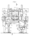
- Each unit comprises a vertical rod 1 movable upward and downward and reversible rotatable, a movable frame 2 attached to the vertical rod 1 and movable therewith upward and downward while permitting the reversible rotation of the vertical rod 1, a pair of pressure arms 5, 6 supported at their lower portions by the movable frame 2 so as to be pivotally movable about a pair of horizontal axes parallel to each other, a pair of seal bars 3, 4 fixed to the upper portions of the pressure arms 5, 6 respectively and opposed to each other.
- one of the seal bars 3, 4 has embedded therein a heater for heat sealing, and the other seal bar is provided with a cutter.
- the two movable frame 2 are moved vertically alternately in different directions in synchronism at a specified stroke.
- the two seal bars 3, 4 move toward each other to a closed position, whereby the tube W is transversely pressed over a predetermined width for sealing.
- the seal bars 3, 4 in pressing contact with the tube W descend with the movable frame 2, whereby the tube W is advanced a distance corresponding to the length of one container.
- the cutter operates, cutting the tube W at the middle of the seal width, whereupon the seal bars 3, 4 open to release the tube W.
- the leading end portion of the tube W corresponding to one container is separated from the remaining tube portion.
- a pair of divided front and rear movable pressing dies 7 which are in the form of a rectangular tube when combined, and a pair of right and left movable ear forming pieces 8.
- Each movable pressing die 7 has a roller 9. When moving along a cam 10, these rollers 9 pivotally move the dies 7 away from each other about their lower ends.
- the movable pressing dies 7 define a shape in conformity with the exter nal shape of the box-like container to be finally obtained.
- the dies 7 When combined together in pressing contact with the tubeW, the dies 7 form a flat tube end and give a rectangular cross section to the tube W for shaping the box-like container. At the same time, a quantity of contents is measured out.
- the movable ear forming pieces 8 are generally L-shaped in cross section and are pivotally movable about their lower ends in directions opposite to each other by a horizontally movable bar 11 mounted on the upper portions of the pressure arms 5, 6 and unillustrated racks and pinions.
- the bar 11 has a projecting end which is connected to a cam 12 and a follower 13 for moving the bar.
- the ear forming pieces 8 cooperate with the pressing dies 7 to form a projecting triangular ear at the flat tube end.
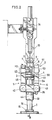
- the vertical rod 1 is rotatably and vertically movably supported by upper and lower two bearing members 14, 15 which are positioned close to its upper and lower ends.
- the portion of the vertical rod 1 supported by the lower bearing member 15 is splined as at 16.
- the upper end of the splined portion 16 is provided with a flange 17.
- the upper bearing member 14 comprises inner and outer tubes 18, 19 and upper and lower ball bearings 20 provided between the two tubes 18, 19.
- the inner tube 18 is slidably fitted around the vertical rod 1 with a bush 21 interposed therebetween.
- the outer tube 19 is secured to an unillustrated frame.
- the lower bearing member 15 comprises inner and outer tubes 22, 23 and upper and lower ball bearings 24 provided between the two tubes 22, 23.
- the inner ring 22 is fitted around the splined portion 16 and is rotatable with the vertical rod 1.
- An arm 25 fixed to the lower end of the inner tube 22 has a forward end which is connected to one end of a rod 26 extending from the drive means to be described later.
- the outer tube 23 is fixed to a frame 27.
- the lower end of the vertical rod 1 extending downward from the lower bearing members 15 is fixed to a vertical rod connector 28 in alignment therewith.
- a horizontal rod member 29 intersects and is attached to the connector 28 by means of a bush 30.
- a pair of vertical parallel rods 31 have lower ends connected to the opposite ends of the rod member 29 and upper ends connected to the drive means by a frame-like connector 32.
- the movable frame 2 comprises a vertical tubular portion 33, and a pair of opposed walls 35, 36 made integral with the lengthwise midportion of the tubular portion 33 by a connecting portion 34.
- the tubular portion 33 is fitted around the vertical rod 1, with a pair of upper and lower bushes 37, 38 interposed therebetween, and bears on the flange 17.
- Each of the opposed walls 35, 36 is formed with two front and rear holes 39, 40 spaced apart by a distance.
- the holes 39, 40 have fitted therein bearings 41 by which a pair of front and rear horizontal support rods 42, 43 are supported on the opposed walls 35, 36.
- the right wall 36 has mounted on its outer surface a pair of front and rear rollers 44 nipping a vertical guide rail 46 attached to a post 45, whereby the movable frame 2 is held against rotation (see Fig. 1).
- the opening of each of the holes 39, 40 has a cover 47 for retaining the bearing.
- Each of the pressure arms 5, 6 comprises a flat rectangular parallelepipedal block 48 (49) fixedly mounted on the horizontal support rod 42 (43) at its lower end and having a thickness in the front-to-rear direction, a horizontal bar 50 (51) placed, at the left half of its lenght, on the top of the block 48 (49) and projecting rightward beyond the block, and a column block 52 (53) having an approximately square cross section and suspended from the projecting portion of the horizontal bar 50 (51).
- the seal bars 3, 4 are secured to the opposed sides of the column blocks 52, 53, respectively, in a projecting fashion.
- a pair of rods 54, 55 are connected, each at its one end, to the flat blocks 48, 49 approximately at the midportion of the height of the blocks.
- the other ends of the rods 54, 55 are connected by vertical pins 59 and spherical bearings 60 to a horizontal rotatable member 58 at the opposite sides of the center of rotation of the member 58.
- the rotatable member 58 is concentrically fitted to the vertical rod 1 and keyed thereto as if pressing the tubular portion 33 of the movable frame 2 from above.
- a cap nut 61 fitting around the vertical rod 1 is placed over the rotatable member 58 and screwed on the rod 1, whereby the number 58 is fastened to the rod 1.
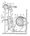
- the seal bar 4 on the rear pressure arm 6 is provided at its opposite sides with a pair of stationary engaging members 63 integral with the bar 4 and each having an upwardly open engaging recess 62.
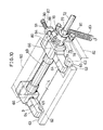
- Each of movable engaging members 64 has a downward engaging projection 65 in engagement with the stationary engaging member (see Figs. 2, 9 and 10).
- each movable engaging member 64 is attached to the piston rod 67 of a hydraulic cylinder 66.
- the hydraulic c ylinder 66 is integral with each end of a horizontal rotatable shaft 69 extending through the column block 52 on the front pressure arm 5 and rotatably supported by a pair of bushes 68 therein.
- the cylinder 66 houses a double compression coiled spring 70 for biasing the piston rod 67 outward.
- the two hydraulic cylinders 66 are in communication with each other through a channel 71 extending through the rotatable shaft axially thereof.
- a working fluid supply pipe 72 has at its left end a flange 73 which is bolted to the right side face of the right hydraulic cylinder 66, whereby the pipe 72 is fixed to the rotatable shaft 69 in alignment therewith.
- the pipe 72 extends through and is rotatably supported by an upper portion of the flat block 48 on the front pressure arm 5.
- the pipe 72 has a projecting right end having a connector 74, to which an unillustrated working fluid duct is attached.
- a work lever 75 is mounted on the pipe 72 in contact with its flange 73.
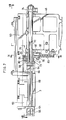
- the work lever 75 has a boss 77 rotatably fitted around the pipe 72 with a bush 76 provided therebetween, a downward arm 78 extending downward from the boss 77, a forward arm 79 extending forward from the boss 77, and a bifurcated upward arm 80 extending upward from the boss 77.
- a roller 81 is mounted on a free end of the downward arm 78.
- a pusher member 82 in the form of a horizontally elongated flat plate is secured to the rear pressure arm 6 so as to be po sitioned behind the roller 81.
- the pusher member 82 has a free end slanting forwardly upward.
- a coiled tension spring 83 has one end attached to the free end of the forward arm 79 and the other end positioned below the work lever 75 and engaged with the left end face of the pressure arm 5.
- the spring 83 biases the work lever 75 clockwise in Fig. 9.
- a movable rod 84 is connected at its one end to the bifurcated end of the upward arm 80 by a horizontal pin 85.
- the movable rod 84 has a stepped portion 86 at an intermediate portion of its length and includes a small-diameter portion 87 extending from the stepped portion 86 to the other end.
- a bracket 88 in the form of a flat square plate for supporting the rod 84 is fixed to the front side of the right hydraulic cylinder 66 and has a right half portion projecting rightward beyond the cylinder 66.
- the small-diameter portion 87 of the rod 84 slidably extends through the bracket 88, with a bush 89 provided therebetween.
- the stepped portion 86 bears against the rear surface of the bracket 88.
- the other end of the rod 84 fixedly carriers a spring retainer 90.
- a coiled compression spring 91 fitting around the small-diameter portion 87 is provided between the bracket 88 and the retainer 90.
- the movable engaging members 64 rotate with the cylinders 66 from the upward position to a horizontal position into engagement with the stationary engaging members 63.
- a working fluid is supplied to the cylinders 66 in this state to retract the piston rods 67, the movable members 64 move forward along with the piston rods 67, with the result that the opposed engaging members 63, 64 pull each other to produce a sealing pressure between the two seal bars 3, 4.
- the opposed engaging members 63, 64 are brought into engagement with each other, there is a slight clearance between the two seal bars 3, 4, but this clearance is eliminated when the engaging members 63, 64 pull each other.
- the two pressure arms 5, 6 are slightly inclined inward from the upright position.
- the movable engaging members 64 For the movable engaging members 64 to remain in a horizontal position at this time, the movable members 64 need to be in a slightly upward position relative to the pressure arm 6. This alteration of position can be realized by the compression of the spring 91 which permits rotation of the cylinders 66 and the work lever 75 in opposite directions relative to each other.
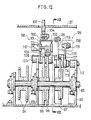
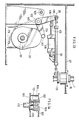
- Figs. 11 to 14 show means for moving the vertical rod upward and downward to move the movable frame similarly and for rotating the vertical rod in forward and reverse directions to open and close the two pressure arms.
- a horizontal cam shaft 92 extending transversely is supported by brackets 93. Fixedly mounted on the cam shaft 92 are sprockets 94, two lift plate cams 95, 96 for moving the rod 1 upward and downward, and a cam 97 for rotating the rod, these members being arranged from left to right.
- the two lift plate cams 95, 96 have different cam contours corresponding to the desired stroke lengths of the movable frame 2. These cams 95, 96 are provided with a common rod lifting cam follower 98, while the rod rotating plate cam 97 is provided with a rotation cam follower 99.
- the lift cam follower 98 is in the form of a steel channel member having an inverted U-shaped cross section and includes a top wall 100 and left and right side walls 101, 102.
- the cam follower 98 extends over the two lift cams 95, 96 in the front-to-rear direction and has a rear end supported by a horizontal shaft 103 on the brackets 93 and a front end to which the aforementioned frame-like connector 32 is connected adjustably in its length.
- a lug 104 is provided on the top wall 100 integrally therewith at a lengthwise intermediate portion thereof.
- a follower restraining hydraulic cylinder has a rod 105 connected to the lug 104.
- a pair of front and rear parallel guide rods 106 extend between and are attached to the walls 101, 102 at a lengthwise intermediate portion thereof.
- a movable piece 107 is supported by the guide rods 106.
- a downwardly projecting roller 108 is mounted on the movable piece 107 by a horizontal pin 109.
- a thin hydraulic cylinder 110 has a piston rod 111 which is connected to the left side face of the movable piece 107.
- the cylinder 110 is attached to the outer surface of the left side wall 101, and the piston rod 111 extends through the left side wall 101.
- the rod rotating cam follower 99 is L-shaped when seen from the front as shown in Fig.
- the forward arm 114 carries at its free end a roller 117 bearing on the rotation cam 97.
- the abovementioned rod 26, connected at its one end to the arm 25, has the other end which is connected to the upward arm 115.
- a follower restraining hydraulic cylinder 118 has a piston rod 119 which is connected to the other upward arm 116.
- the cam shaft 92 When the cam shaft 92 is rotated, one of the lift cams 95, 96 and the follower 98 convert the rotation into a reciprocating motion, which is then delivered to the vertical rod 1 to move the rod 1 upward and downward.
- the vertical stroke of the rod 1 corresponds to the length of one container to be formed from the tube W, so that when the length is to be altered, the thin hydraulic cylinder 110 is operated to shift the movable piece 107 and bring the roller 108 out of contact with one of the two plate cams 95, 96 into contact with the other cam.
- the rotation cam 97 and the follower 99 convert the rotation of the cam shaft 92 to a reciprocating motion, which is delivered to the rod 26, reciprocatingly moving the rod 26 longitudinally thereof.
- the arm 25 connected to the rod 26 is therefore pivotally moved to move the inner tube 22 and the vertical rod 1 in the forward and reverse direction.
Landscapes
- Engineering & Computer Science (AREA)
- Mechanical Engineering (AREA)
- Physics & Mathematics (AREA)
- Fluid Mechanics (AREA)
- Package Closures (AREA)
Applications Claiming Priority (6)
| Application Number | Priority Date | Filing Date | Title |
|---|---|---|---|
| JP214796/84 | 1984-10-12 | ||
| JP59214795A JPS6193010A (ja) | 1984-10-12 | 1984-10-12 | 包装機械における容器成形装置 |
| JP59214796A JPS6193011A (ja) | 1984-10-12 | 1984-10-12 | 包装機械における容器成形装置 |
| JP214797/84 | 1984-10-12 | ||
| JP214795/84 | 1984-10-12 | ||
| JP59214797A JPS6193012A (ja) | 1984-10-12 | 1984-10-12 | 包装機械における容器成形装置 |
Related Parent Applications (1)
| Application Number | Title | Priority Date | Filing Date |
|---|---|---|---|
| EP85201661.7 Division | 1985-10-11 |
Publications (3)
| Publication Number | Publication Date |
|---|---|
| EP0258953A2 true EP0258953A2 (fr) | 1988-03-09 |
| EP0258953A3 EP0258953A3 (en) | 1988-03-30 |
| EP0258953B1 EP0258953B1 (fr) | 1990-11-14 |
Family
ID=27329668
Family Applications (3)
| Application Number | Title | Priority Date | Filing Date |
|---|---|---|---|
| EP87202010A Expired - Lifetime EP0258953B1 (fr) | 1984-10-12 | 1985-10-11 | Dispositif de traitement d'un tube pour former des récipients d'emballage |
| EP85201661A Expired EP0178732B1 (fr) | 1984-10-12 | 1985-10-11 | Dispositif de traitement d'un tube pour former des récipients d'emballage |
| EP87202011A Expired - Lifetime EP0265021B1 (fr) | 1984-10-12 | 1985-10-11 | Dispositif de traitement d'un tube pour former des récipients d'emballage |
Family Applications After (2)
| Application Number | Title | Priority Date | Filing Date |
|---|---|---|---|
| EP85201661A Expired EP0178732B1 (fr) | 1984-10-12 | 1985-10-11 | Dispositif de traitement d'un tube pour former des récipients d'emballage |
| EP87202011A Expired - Lifetime EP0265021B1 (fr) | 1984-10-12 | 1985-10-11 | Dispositif de traitement d'un tube pour former des récipients d'emballage |
Country Status (5)
| Country | Link |
|---|---|
| US (1) | US4628670A (fr) |
| EP (3) | EP0258953B1 (fr) |
| KR (1) | KR890001585B1 (fr) |
| CN (1) | CN1004199B (fr) |
| DE (2) | DE3580593D1 (fr) |
Cited By (1)
| Publication number | Priority date | Publication date | Assignee | Title |
|---|---|---|---|---|
| EP0832821A1 (fr) * | 1996-09-30 | 1998-04-01 | Shikoku Kakoki Co., Ltd. | Presse dans une machine de remplissage et d'emballage |
Families Citing this family (11)
| Publication number | Priority date | Publication date | Assignee | Title |
|---|---|---|---|---|
| IT1248217B (it) * | 1991-03-11 | 1995-01-05 | Ica Spa | Confezionatrice verticale a due tubi formatori contrapposti. |
| JP3413540B2 (ja) * | 1995-03-16 | 2003-06-03 | 四国化工機株式会社 | 包装材料チューブのシール装置 |
| ES2152127B1 (es) * | 1996-04-03 | 2001-08-01 | Sanko Kikai | Controlador de funcionamiento para maquina empaquetadora automatica multiple. |
| JP3585638B2 (ja) * | 1996-04-03 | 2004-11-04 | 三光機械株式会社 | 多連式自動包装機 |
| JP3847391B2 (ja) * | 1996-11-26 | 2006-11-22 | 四国化工機株式会社 | 充填包装機械のプレス装置 |
| AU716763B2 (en) * | 1997-11-20 | 2000-03-09 | Orihiro Engineering Co., Ltd. | Forming, filling and sealing machine for standing pouch |
| PT1101700E (pt) | 1999-11-18 | 2004-08-31 | Tetra Laval Holdings & Finance | Unidade de formacao e vedacao para maquina de embalar produtos alimentares escoaveis |
| EP1325868A1 (fr) * | 2002-01-08 | 2003-07-09 | Tetra Laval Holdings & Finance SA | Machine d'emballage pour produire en continu des emballages scellés contenant un produit alimentaire sous forme liquide, dans un matériau d'emballage tubulaire |
| ATE491638T1 (de) * | 2007-09-28 | 2011-01-15 | Tetra Laval Holdings & Finance | Element zum formen von gesiegelten verpackungen mit flüssigen nahrungsmitteln aus einem verpackungsmaterialschlauch |
| CN109502800B (zh) * | 2018-10-17 | 2020-07-03 | 南京大学环境规划设计研究院股份公司 | 一种城镇污水深度处理反应池 |
| CN111003296A (zh) * | 2019-11-29 | 2020-04-14 | 北京小米移动软件有限公司 | 包装箱、夹持位置检测方法、夹持位置检测装置 |
Family Cites Families (6)
| Publication number | Priority date | Publication date | Assignee | Title |
|---|---|---|---|---|
| US2869298A (en) * | 1954-01-15 | 1959-01-20 | Package Machinery Co | Automatic packaging machine |
| US2837883A (en) * | 1956-09-06 | 1958-06-10 | Package Machinery Co | Automatic packaging machine |
| US3050916A (en) * | 1961-04-24 | 1962-08-28 | Hayssen Mfg Company | Packaging machine film sealing mechanism |
| US3449888A (en) * | 1965-09-15 | 1969-06-17 | Hayssen Mfg Co | Packaging machine |
| US3589913A (en) * | 1965-10-20 | 1971-06-29 | New Jersey Machine Corp | Method of making connected packages |
| SE454584B (sv) * | 1982-04-13 | 1988-05-16 | Tetra Pak Ab | Anordning for bearbetning av en tubformig materialbana |
-
1985
- 1985-09-28 KR KR1019850007195A patent/KR890001585B1/ko not_active Expired
- 1985-09-30 US US06/781,857 patent/US4628670A/en not_active Expired - Lifetime
- 1985-10-10 CN CN85107458.8A patent/CN1004199B/zh not_active Expired
- 1985-10-11 EP EP87202010A patent/EP0258953B1/fr not_active Expired - Lifetime
- 1985-10-11 DE DE8787202011T patent/DE3580593D1/de not_active Expired - Fee Related
- 1985-10-11 EP EP85201661A patent/EP0178732B1/fr not_active Expired
- 1985-10-11 DE DE8787202010T patent/DE3580592D1/de not_active Expired - Fee Related
- 1985-10-11 EP EP87202011A patent/EP0265021B1/fr not_active Expired - Lifetime
Cited By (2)
| Publication number | Priority date | Publication date | Assignee | Title |
|---|---|---|---|---|
| EP0832821A1 (fr) * | 1996-09-30 | 1998-04-01 | Shikoku Kakoki Co., Ltd. | Presse dans une machine de remplissage et d'emballage |
| CN1076693C (zh) * | 1996-09-30 | 2001-12-26 | 四国化工机株式会社 | 填充包装机用挤压装置 |
Also Published As
| Publication number | Publication date |
|---|---|
| CN85107458A (zh) | 1986-05-10 |
| EP0178732A1 (fr) | 1986-04-23 |
| DE3580593D1 (de) | 1990-12-20 |
| EP0258953B1 (fr) | 1990-11-14 |
| EP0265021B1 (fr) | 1990-11-14 |
| EP0265021A1 (fr) | 1988-04-27 |
| EP0178732B1 (fr) | 1988-11-23 |
| CN1004199B (zh) | 1989-05-17 |
| US4628670A (en) | 1986-12-16 |
| KR860003141A (ko) | 1986-05-21 |
| DE3580592D1 (de) | 1990-12-20 |
| KR890001585B1 (ko) | 1989-05-09 |
| EP0258953A3 (en) | 1988-03-30 |
Similar Documents
| Publication | Publication Date | Title |
|---|---|---|
| EP0258953B1 (fr) | Dispositif de traitement d'un tube pour former des récipients d'emballage | |
| EP0315381B1 (fr) | Dispositif de transfert pour presses transferts | |
| EP0228362B1 (fr) | Dispositif pour le traitement d'une bande de matériau | |
| US3324621A (en) | Packaging machine | |
| US4741195A (en) | Apparatus for clamping and unclamping feed bars for a transfer press | |
| GB2210310A (en) | Tube cut off die set | |
| CA1144061A (fr) | Sectionneur mecanique commande par came | |
| US3461760A (en) | Trimming apparatus | |
| CN112623331B (zh) | 插棒类食品生产设备及生产方法 | |
| US5088365A (en) | Notching apparatus for a double cut die set | |
| CN2225320Y (zh) | 圆环链自动编结机 | |
| US4304347A (en) | Apparatus for feeding material to a metalworking machine | |
| JPH0123366B2 (fr) | ||
| JPH0750014Y2 (ja) | ウィングベンダー | |
| CN211493009U (zh) | 全自动试样袋制袋焊管设备 | |
| JPH0117923B2 (fr) | ||
| US3815803A (en) | Feed device for forming apparatus | |
| JPS6193012A (ja) | 包装機械における容器成形装置 | |
| CN222728308U (zh) | 一种口含烟包装机 | |
| JPH02160121A (ja) | 枠材製造用折曲げ装置 | |
| CN216035518U (zh) | 一种双出大包装全伺服给带式包装输送系统 | |
| SU969380A1 (ru) | Устройство дл подачи заготовок в рабочую зону пресса | |
| US3450036A (en) | Half shell | |
| US3780561A (en) | Feed device for forming apparatus | |
| JPH0239611Y2 (fr) |
Legal Events
| Date | Code | Title | Description |
|---|---|---|---|
| PUAI | Public reference made under article 153(3) epc to a published international application that has entered the european phase |
Free format text: ORIGINAL CODE: 0009012 |
|
| PUAL | Search report despatched |
Free format text: ORIGINAL CODE: 0009013 |
|
| AC | Divisional application: reference to earlier application |
Ref document number: 178732 Country of ref document: EP |
|
| AK | Designated contracting states |
Kind code of ref document: A2 Designated state(s): CH DE FR GB LI NL SE |
|
| AK | Designated contracting states |
Kind code of ref document: A3 Designated state(s): CH DE FR GB LI NL SE |
|
| 17P | Request for examination filed |
Effective date: 19880811 |
|
| 17Q | First examination report despatched |
Effective date: 19900118 |
|
| GRAA | (expected) grant |
Free format text: ORIGINAL CODE: 0009210 |
|
| AC | Divisional application: reference to earlier application |
Ref document number: 178732 Country of ref document: EP |
|
| AK | Designated contracting states |
Kind code of ref document: B1 Designated state(s): CH DE FR GB LI NL SE |
|
| REF | Corresponds to: |
Ref document number: 3580592 Country of ref document: DE Date of ref document: 19901220 |
|
| ET | Fr: translation filed | ||
| PLBE | No opposition filed within time limit |
Free format text: ORIGINAL CODE: 0009261 |
|
| STAA | Information on the status of an ep patent application or granted ep patent |
Free format text: STATUS: NO OPPOSITION FILED WITHIN TIME LIMIT |
|
| 26N | No opposition filed | ||
| EAL | Se: european patent in force in sweden |
Ref document number: 87202010.2 |
|
| REG | Reference to a national code |
Ref country code: GB Ref legal event code: IF02 |
|
| PGFP | Annual fee paid to national office [announced via postgrant information from national office to epo] |
Ref country code: CH Payment date: 20021010 Year of fee payment: 18 |
|
| PGFP | Annual fee paid to national office [announced via postgrant information from national office to epo] |
Ref country code: SE Payment date: 20021017 Year of fee payment: 18 |
|
| PGFP | Annual fee paid to national office [announced via postgrant information from national office to epo] |
Ref country code: NL Payment date: 20021029 Year of fee payment: 18 |
|
| PGFP | Annual fee paid to national office [announced via postgrant information from national office to epo] |
Ref country code: GB Payment date: 20031006 Year of fee payment: 19 |
|
| PG25 | Lapsed in a contracting state [announced via postgrant information from national office to epo] |
Ref country code: SE Free format text: LAPSE BECAUSE OF NON-PAYMENT OF DUE FEES Effective date: 20031012 |
|
| PGFP | Annual fee paid to national office [announced via postgrant information from national office to epo] |
Ref country code: FR Payment date: 20031027 Year of fee payment: 19 |
|
| PG25 | Lapsed in a contracting state [announced via postgrant information from national office to epo] |
Ref country code: LI Free format text: LAPSE BECAUSE OF NON-PAYMENT OF DUE FEES Effective date: 20031031 Ref country code: CH Free format text: LAPSE BECAUSE OF NON-PAYMENT OF DUE FEES Effective date: 20031031 |
|
| PGFP | Annual fee paid to national office [announced via postgrant information from national office to epo] |
Ref country code: DE Payment date: 20031031 Year of fee payment: 19 |
|
| PG25 | Lapsed in a contracting state [announced via postgrant information from national office to epo] |
Ref country code: NL Free format text: LAPSE BECAUSE OF NON-PAYMENT OF DUE FEES Effective date: 20040501 |
|
| EUG | Se: european patent has lapsed | ||
| REG | Reference to a national code |
Ref country code: CH Ref legal event code: PL |
|
| NLV4 | Nl: lapsed or anulled due to non-payment of the annual fee |
Effective date: 20040501 |
|
| PG25 | Lapsed in a contracting state [announced via postgrant information from national office to epo] |
Ref country code: GB Free format text: LAPSE BECAUSE OF NON-PAYMENT OF DUE FEES Effective date: 20041011 |
|
| PG25 | Lapsed in a contracting state [announced via postgrant information from national office to epo] |
Ref country code: DE Free format text: LAPSE BECAUSE OF NON-PAYMENT OF DUE FEES Effective date: 20050503 |
|
| GBPC | Gb: european patent ceased through non-payment of renewal fee |
Effective date: 20041011 |
|
| PG25 | Lapsed in a contracting state [announced via postgrant information from national office to epo] |
Ref country code: FR Free format text: LAPSE BECAUSE OF NON-PAYMENT OF DUE FEES Effective date: 20050630 |
|
| REG | Reference to a national code |
Ref country code: FR Ref legal event code: ST |