EP0259027A2 - Temperaturfühlersystem - Google Patents
Temperaturfühlersystem Download PDFInfo
- Publication number
- EP0259027A2 EP0259027A2 EP87307047A EP87307047A EP0259027A2 EP 0259027 A2 EP0259027 A2 EP 0259027A2 EP 87307047 A EP87307047 A EP 87307047A EP 87307047 A EP87307047 A EP 87307047A EP 0259027 A2 EP0259027 A2 EP 0259027A2
- Authority
- EP
- European Patent Office
- Prior art keywords
- phosphor
- measuring system
- temperature sensing
- tube
- signal
- Prior art date
- Legal status (The legal status is an assumption and is not a legal conclusion. Google has not performed a legal analysis and makes no representation as to the accuracy of the status listed.)
- Withdrawn
Links
- 239000013307 optical fiber Substances 0.000 claims abstract description 9
- 230000001419 dependent effect Effects 0.000 claims abstract description 8
- 238000004020 luminiscence type Methods 0.000 claims abstract description 7
- OAICVXFJPJFONN-UHFFFAOYSA-N Phosphorus Chemical compound [P] OAICVXFJPJFONN-UHFFFAOYSA-N 0.000 claims description 34
- 239000000523 sample Substances 0.000 claims description 23
- 239000000835 fiber Substances 0.000 claims description 15
- 230000005855 radiation Effects 0.000 claims description 10
- PNEYBMLMFCGWSK-UHFFFAOYSA-N Alumina Chemical compound [O-2].[O-2].[O-2].[Al+3].[Al+3] PNEYBMLMFCGWSK-UHFFFAOYSA-N 0.000 claims description 7
- 239000011521 glass Substances 0.000 claims description 4
- 238000012806 monitoring device Methods 0.000 claims description 4
- 230000003287 optical effect Effects 0.000 claims description 4
- 239000004033 plastic Substances 0.000 claims description 4
- 229920003023 plastic Polymers 0.000 claims description 4
- 239000000843 powder Substances 0.000 claims description 4
- 229910052724 xenon Inorganic materials 0.000 claims description 4
- FHNFHKCVQCLJFQ-UHFFFAOYSA-N xenon atom Chemical compound [Xe] FHNFHKCVQCLJFQ-UHFFFAOYSA-N 0.000 claims description 4
- 239000002184 metal Substances 0.000 claims description 3
- 229910052751 metal Inorganic materials 0.000 claims description 3
- VYZAMTAEIAYCRO-UHFFFAOYSA-N Chromium Chemical compound [Cr] VYZAMTAEIAYCRO-UHFFFAOYSA-N 0.000 claims description 2
- 229910010293 ceramic material Inorganic materials 0.000 claims description 2
- 229910052804 chromium Inorganic materials 0.000 claims description 2
- 239000011651 chromium Substances 0.000 claims description 2
- 238000012544 monitoring process Methods 0.000 abstract description 5
- 239000000463 material Substances 0.000 abstract description 4
- 230000005284 excitation Effects 0.000 abstract description 3
- 239000003990 capacitor Substances 0.000 description 4
- 229910001369 Brass Inorganic materials 0.000 description 3
- 239000010951 brass Substances 0.000 description 3
- 238000010276 construction Methods 0.000 description 3
- 239000000853 adhesive Substances 0.000 description 2
- 230000001070 adhesive effect Effects 0.000 description 2
- 238000005259 measurement Methods 0.000 description 2
- 229920000647 polyepoxide Polymers 0.000 description 2
- 238000012545 processing Methods 0.000 description 2
- 230000001681 protective effect Effects 0.000 description 2
- 239000010979 ruby Substances 0.000 description 2
- 229910001750 ruby Inorganic materials 0.000 description 2
- RYGMFSIKBFXOCR-UHFFFAOYSA-N Copper Chemical compound [Cu] RYGMFSIKBFXOCR-UHFFFAOYSA-N 0.000 description 1
- 239000004593 Epoxy Substances 0.000 description 1
- XUIMIQQOPSSXEZ-UHFFFAOYSA-N Silicon Chemical compound [Si] XUIMIQQOPSSXEZ-UHFFFAOYSA-N 0.000 description 1
- 239000010949 copper Substances 0.000 description 1
- 229910052802 copper Inorganic materials 0.000 description 1
- 229910052593 corundum Inorganic materials 0.000 description 1
- 230000005611 electricity Effects 0.000 description 1
- 239000003822 epoxy resin Substances 0.000 description 1
- 238000000034 method Methods 0.000 description 1
- 238000012986 modification Methods 0.000 description 1
- 230000004048 modification Effects 0.000 description 1
- 239000011253 protective coating Substances 0.000 description 1
- 229920005989 resin Polymers 0.000 description 1
- 239000011347 resin Substances 0.000 description 1
- 229910052710 silicon Inorganic materials 0.000 description 1
- 239000010703 silicon Substances 0.000 description 1
- 229920002050 silicone resin Polymers 0.000 description 1
- 125000000391 vinyl group Chemical group [H]C([*])=C([H])[H] 0.000 description 1
- 229920002554 vinyl polymer Polymers 0.000 description 1
- 230000000007 visual effect Effects 0.000 description 1
- 229910001845 yogo sapphire Inorganic materials 0.000 description 1
Images

Classifications
-
- G—PHYSICS
- G01—MEASURING; TESTING
- G01K—MEASURING TEMPERATURE; MEASURING QUANTITY OF HEAT; THERMALLY-SENSITIVE ELEMENTS NOT OTHERWISE PROVIDED FOR
- G01K11/00—Measuring temperature based upon physical or chemical changes not covered by groups G01K3/00, G01K5/00, G01K7/00 or G01K9/00
- G01K11/32—Measuring temperature based upon physical or chemical changes not covered by groups G01K3/00, G01K5/00, G01K7/00 or G01K9/00 using changes in transmittance, scattering or luminescence in optical fibres
- G01K11/3206—Measuring temperature based upon physical or chemical changes not covered by groups G01K3/00, G01K5/00, G01K7/00 or G01K9/00 using changes in transmittance, scattering or luminescence in optical fibres at discrete locations in the fibre, e.g. using Bragg scattering
- G01K11/3213—Measuring temperature based upon physical or chemical changes not covered by groups G01K3/00, G01K5/00, G01K7/00 or G01K9/00 using changes in transmittance, scattering or luminescence in optical fibres at discrete locations in the fibre, e.g. using Bragg scattering using changes in luminescence, e.g. at the distal end of the fibres
Definitions
- This invention relates to a system for sensing and measuring temperatures by means of an optical technique, utilising a phosphor having a luminescent decay time which is dependent upon the temperature of the phosphor.
- a temperature sensing and measuring system comprises at least one probe containing a phosphor having a luminescent decay time which is dependent upon the temperature of the phosphor; means for producing a pulse of radiation having a wavelength capable of exciting the phosphor to luminescence; one or more optical fibres for directing said radiation on to the phosphor and for directing the luminescent emission from the phosphor to a monitoring device capable of deriving a first electrical signal which varies with the degree of luminescence; means responsive to the pulse of radiation for deriving a second electrical signal having a value dependent upon the intensity of the pulse and for storing such signal; means for integrating the first signal produced by the monitoring device over a predetermined time period for producing a third electrical signal having a value representing said integrated first signal, and means for dividing the second signal by the third signal and for providing an output signal which is dependent on the result thereof.
- the output signal which may be termed the decay time constant, is a function of the temperature of the phosphor.
- the signal processing can be implemented using readily available devices.
- the phosphor employed must have a decay time which varies significantly over the temperature range of interest.
- a suitable phosphor is aluminium oxide powder doped with chromium (Al2O3: Cr3+) commonly known as ruby, the decay time varying from about 3.5mS at 0°C to about 1mS at 200°C.
- a xenon flash lamp is used as the excitation means, this having a short arc length producing a highly intense light flash, the pulse energy for producing the light flash conveniently being stored in a capacitor or capacitor bank.
- the excitation source may be a light-emitting diode.
- the same optical fibre or fibres may be used for conveying the light pulse to the phosphor and for carrying the emission from the phosphor.
- the invention may be used, for example, for monitoring the temperature within high power electricity generators.
- the probe may possibly consist of a metal tube, for example of brass, closed at one end and having an optical fibre sealed into the opposite end, the phosphor being located within the tube between the end of the fibre and the closed end of the tube.
- a metal tube for example of brass
- the phosphor being located within the tube between the end of the fibre and the closed end of the tube.
- other forms of probe may be used, such as tubes formed from glass, plastics or ceramic material.
- a number of probes and associated optical fibres may be used to monitor the temperature at different positions within the generator.
- a single flash lamp or separate light-emitting diodes may be used to launch light simultaneously into the different fibres.
- the invention is especially suitable for use in monitoring the temperature within electrical generators, it will be appreciated that it has a number of different applications, where the remote measurement of temperature is required to be carried out.
- the apparatus comprises a short arc length xenon flash lamp 1 arranged to be operated periodically by means of a triggering circuit of any convenient form, a reservoir capacitor or capacitor bank 2, charged from an appropriate power source 3, providing the energy necessary for producing a series of high intensity light pulses from the lamp.
- An optical fibre 4 conveys the light pulses to a probe 5 in the form of a short brass tube 6 containing a quantity of powdered ruby phosphor 7, which has a luminescent decay time which varies with temperature, the fibre being sealed in a gas- and liquid-tight manner into one end of the tube, the opposite end of which is closed by a plug 8. The end of the fibre within the tube 6 is in contact with the phosphor powder.
- the phosphor luminesces in an exponentially decaying manner, the light from the phosphor travelling back along the fibre 4, and passing via a coupler 20 to a silicon pin diode detector 9 which converts it into a first electrical signal.
- This signal is then amplified, by means of an amplifier 10, and fed to an integrator 11 in a signal processor 12.
- a second electrical signal, derived from the initial light pulse fed along the fibre 4 to the probe 5, is fed to a sample/hold circuit 13 also within the signal processor 12.
- the output of the integrator 11, in the form of a third electrical signal, is then fed, together with the second signal from the stored sample/hold circuit 13, to an analogue divider 14 which divides the second signal by the third, giving an output signal which is representative of the temperature of the phosphor within the probe 5 and hence of the environment within which the probe is located, the signal being fed to a suitable indicator 22.
- the system is conveniently employed for monitoring the temperature within a high voltage electrical generator, and for this purpose the fibre 4 may be coated with one or more layers of a protective plastic or other material to form a rugged cable, gas tight connectors of any convenient kind enabling connections to be made through the outer wall of the generator.
- a protective plastic or other material to form a rugged cable, gas tight connectors of any convenient kind enabling connections to be made through the outer wall of the generator.
- One probe for such a purpose may, for example, be constructed as illustrated in Figure 2, the fibre 4, with a protective coating 15, being sealed within the wider end 16 of a stepped brass tube 6 by means of a vinyl adhesive 17, with the uncoated fibre projecting into the narrower end 18 of the tube.
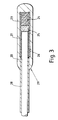
- the probe may, for example, be constructed as shown in Figure 3.
- Part of the cabling 28 covering the optical fibre 20 is removed.
- the exposed fibre 20 is then sealed within a glass capillary tube 26 using an epoxy resin 27 to hold it in position.
- a protective cap 23 covers the capillary tube 26 and part of the cabling 28.
- the phosphor 25 is held against the optical fibre 20 by a block of resin 24 which seals the end of the capillary tube 26.
- a plurality of probes 5 are located in different positions within the generator and connected to respective detector, signal processing and indicator circuits.
- a common xenon flash lamp may, however, be used to feed light pulses into all the fibres.
- the indicator 22 may take any convenient form, and may actuate a warning device in the event that the temperature at a position occupied by a probe exceeds a predetermined value. Such a device may be arranged to give an audible and/or visual warning signal. The temperature readings may also be continuously recorded.
- probe employed can be varied to suit any particular application of the invention.
- the phosphor may be bonded to the end of the fibre or to a material which is itself attached to the fibre.
- the phosphor may be embedded in a glass which is cut to size and attached to the fibre end by a suitable bonding medium, which may be an epoxy or silicone resin.
- the probe may be encapsulated if desired, for example in a metal or plastic tube.
- Modification in other parts of the measuring system may also be made.
- a suitable analogue to digital converter may be employed together with a microprocessor for carrying out the division step.
- a microprocessor may also be arranged to carry out other functions, possibly including certain control measures.
Landscapes
- Physics & Mathematics (AREA)
- General Physics & Mathematics (AREA)
- Investigating, Analyzing Materials By Fluorescence Or Luminescence (AREA)
- Measuring Temperature Or Quantity Of Heat (AREA)
Applications Claiming Priority (2)
| Application Number | Priority Date | Filing Date | Title |
|---|---|---|---|
| GB8621077 | 1986-09-01 | ||
| GB868621077A GB8621077D0 (en) | 1986-09-01 | 1986-09-01 | Temperature sensing system |
Publications (2)
| Publication Number | Publication Date |
|---|---|
| EP0259027A2 true EP0259027A2 (de) | 1988-03-09 |
| EP0259027A3 EP0259027A3 (de) | 1989-04-05 |
Family
ID=10603506
Family Applications (1)
| Application Number | Title | Priority Date | Filing Date |
|---|---|---|---|
| EP87307047A Withdrawn EP0259027A3 (de) | 1986-09-01 | 1987-08-07 | Temperaturfühlersystem |
Country Status (3)
| Country | Link |
|---|---|
| US (1) | US4776827A (de) |
| EP (1) | EP0259027A3 (de) |
| GB (2) | GB8621077D0 (de) |
Cited By (4)
| Publication number | Priority date | Publication date | Assignee | Title |
|---|---|---|---|---|
| DE8808168U1 (de) * | 1988-05-12 | 1988-09-15 | Degussa Ag, 6000 Frankfurt | Vorrichtung zur Temperaturmessung mit einem Sensorkörper |
| EP0379941A3 (de) * | 1989-01-24 | 1991-05-08 | Tacan Corporation | Fluoreszenz-Material |
| WO1994002813A1 (en) * | 1992-07-16 | 1994-02-03 | Rosemount Inc. | Optical temperature probe assembly |
| WO2012158681A3 (en) * | 2011-05-16 | 2013-04-11 | General Electric Company | Method and system for embedded temperature and/or strain sensors |
Families Citing this family (31)
| Publication number | Priority date | Publication date | Assignee | Title |
|---|---|---|---|---|
| US5090818A (en) * | 1982-08-06 | 1992-02-25 | Kleinerman Marcos Y | Fiber optic systems for sensing temperature and other physical variables |
| US5222810A (en) * | 1982-08-06 | 1993-06-29 | Kleinerman Marcos Y | Fiber optic systems for sensing temperature and other physical variables |
| US5673750A (en) * | 1990-05-19 | 1997-10-07 | Hitachi, Ltd. | Vacuum processing method and apparatus |
| US5556204A (en) * | 1990-07-02 | 1996-09-17 | Hitachi, Ltd. | Method and apparatus for detecting the temperature of a sample |
| US5140609A (en) * | 1990-10-18 | 1992-08-18 | Rosemount Inc. | Trd temperature sensor |
| US5211480A (en) * | 1990-10-18 | 1993-05-18 | Rosemount Inc. | TRD temperature sensor and electronics |
| US5255980A (en) * | 1990-10-18 | 1993-10-26 | Rosemount Inc. | Black body TRD temperature sensor |
| US5107445A (en) * | 1990-12-04 | 1992-04-21 | Luxtron Corporation | Modular luminescence-based measuring system using fast digital signal processing |
| US5183338A (en) * | 1991-04-10 | 1993-02-02 | Luxtron Corporation | Temperature measurement with combined photo-luminescent and black body sensing techniques |
| US5352040A (en) * | 1992-08-24 | 1994-10-04 | Martin Marietta Energy Systems, Inc. | Dual neutron flux/temperature measurement sensor |
| FR2718237B1 (fr) * | 1994-03-30 | 1996-06-21 | Europ Propulsion | Dispositif de mesure optique de température cryogénique. |
| US5730528A (en) * | 1996-08-28 | 1998-03-24 | Lockheed Martin Energy Systems, Inc. | High temperature thermometric phosphors for use in a temperature sensor |
| US6123455A (en) * | 1997-05-02 | 2000-09-26 | American Iron And Steel Institute | Phosphor thermometry system |
| US5949539A (en) * | 1997-11-10 | 1999-09-07 | American Iron And Steel Institute | Real-time method and apparatus for measuring the decay-time constant of a fluorescing phosphor |
| US20020110180A1 (en) * | 2001-02-09 | 2002-08-15 | Barney Alfred A. | Temperature-sensing composition |
| JP3831816B2 (ja) * | 2003-02-13 | 2006-10-11 | 川崎重工業株式会社 | 光ファイバープローブ |
| US20040252748A1 (en) * | 2003-06-13 | 2004-12-16 | Gleitman Daniel D. | Fiber optic sensing systems and methods |
| US20080069180A1 (en) * | 2006-09-19 | 2008-03-20 | Derek Djeu | Fiber optic temperature sensing system using a hemispherical phosphor |
| JP5001119B2 (ja) * | 2007-11-22 | 2012-08-15 | アズビル株式会社 | 温度センサプローブ、及びその製造方法 |
| JP5064183B2 (ja) * | 2007-11-22 | 2012-10-31 | アズビル株式会社 | 温度センサプローブの製造方法 |
| JP4944006B2 (ja) * | 2007-12-17 | 2012-05-30 | 株式会社山武 | 温度センサ、及び温度測定方法 |
| US8201996B1 (en) * | 2008-04-25 | 2012-06-19 | Ipitek, Inc. | Passive wavelength-division multiplexing (WDM) fiber-optic temperature sensor |
| US8206030B1 (en) | 2008-05-19 | 2012-06-26 | Ipitek, Inc. | Multiple sensing tip optical fiber thermometer |
| JP5225752B2 (ja) * | 2008-05-27 | 2013-07-03 | アズビル株式会社 | 蛍光温度センサ |
| EP2561326B1 (de) | 2010-04-17 | 2016-11-23 | Powell Canada Inc. | Photolumineszenter temperatursensor unter verwendung eines einzelnen elements zur anregung und photodetektion |
| US8695430B1 (en) | 2011-11-23 | 2014-04-15 | The United States Of America As Represented By The Administrator Of National Aeronautics And Space Administration | Temperature and pressure sensors based on spin-allowed broadband luminescence of doped orthorhombic perovskite structures |
| US10398508B2 (en) * | 2012-02-07 | 2019-09-03 | Joe Denton Brown | Protective sheath and method of using same for laser surgery |
| US20140269817A1 (en) * | 2013-03-14 | 2014-09-18 | United Technologies Corporation | Phosphor Thermometry Fiber Sensor |
| US9638581B2 (en) | 2014-06-12 | 2017-05-02 | Globalfoundries Inc. | Determining thermal profiles of semiconductor structures |
| TWI603416B (zh) | 2014-07-08 | 2017-10-21 | 瓦特洛威電子製造公司 | 具有接合層之整合溫度感測技術的接合總成 |
| US10996117B1 (en) * | 2020-05-31 | 2021-05-04 | Accelovant Technologies Corporation | Integrated active fiber optic temperature measuring device |
Family Cites Families (7)
| Publication number | Priority date | Publication date | Assignee | Title |
|---|---|---|---|---|
| US3427581A (en) * | 1965-08-04 | 1969-02-11 | Litton Systems Inc | Clear air turbulence detector |
| US4215275A (en) * | 1977-12-07 | 1980-07-29 | Luxtron Corporation | Optical temperature measurement technique utilizing phosphors |
| US4223226A (en) * | 1978-07-26 | 1980-09-16 | Rockwell International Corporation | Fiber optic temperature sensor |
| SE431259B (sv) * | 1979-10-10 | 1984-01-23 | Asea Ab | Fiberoptisk temperaturgivare baserad pa fotoluminiscens hos ett fast material |
| US4708494A (en) * | 1982-08-06 | 1987-11-24 | Marcos Kleinerman | Methods and devices for the optical measurement of temperature with luminescent materials |
| US4596925A (en) * | 1982-10-27 | 1986-06-24 | The Foxboro Company | Fiber optic displacement sensor with built-in reference |
| US4652143A (en) * | 1984-11-29 | 1987-03-24 | Luxtron Corporation | Optical temperature measurement techniques |
-
1986
- 1986-09-01 GB GB868621077A patent/GB8621077D0/en active Pending
-
1987
- 1987-06-03 GB GB8713022A patent/GB2194633B/en not_active Expired - Lifetime
- 1987-08-07 EP EP87307047A patent/EP0259027A3/de not_active Withdrawn
- 1987-08-26 US US07/089,607 patent/US4776827A/en not_active Expired - Fee Related
Cited By (9)
| Publication number | Priority date | Publication date | Assignee | Title |
|---|---|---|---|---|
| DE8808168U1 (de) * | 1988-05-12 | 1988-09-15 | Degussa Ag, 6000 Frankfurt | Vorrichtung zur Temperaturmessung mit einem Sensorkörper |
| EP0379941A3 (de) * | 1989-01-24 | 1991-05-08 | Tacan Corporation | Fluoreszenz-Material |
| WO1994002813A1 (en) * | 1992-07-16 | 1994-02-03 | Rosemount Inc. | Optical temperature probe assembly |
| US5355423A (en) * | 1992-07-16 | 1994-10-11 | Rosemount Inc. | Optical temperature probe assembly |
| WO2012158681A3 (en) * | 2011-05-16 | 2013-04-11 | General Electric Company | Method and system for embedded temperature and/or strain sensors |
| CN103703351A (zh) * | 2011-05-16 | 2014-04-02 | 通用电气公司 | 用于多功能嵌入式传感器的方法和系统 |
| CN103703351B (zh) * | 2011-05-16 | 2016-01-13 | 通用电气公司 | 用于多功能嵌入式传感器的方法和系统 |
| US9482585B2 (en) | 2011-05-16 | 2016-11-01 | General Electric Company | Method and system for multi-functional embedded sensors |
| US9551620B2 (en) | 2011-05-16 | 2017-01-24 | General Electric Company | Method and system for multi-functional embedded sensors |
Also Published As
| Publication number | Publication date |
|---|---|
| GB8713022D0 (en) | 1987-07-08 |
| GB2194633A (en) | 1988-03-09 |
| GB8621077D0 (en) | 1986-10-08 |
| EP0259027A3 (de) | 1989-04-05 |
| US4776827A (en) | 1988-10-11 |
| GB2194633B (en) | 1990-01-10 |
Similar Documents
| Publication | Publication Date | Title |
|---|---|---|
| US4776827A (en) | Temperature sensing system using a phosphor having a temperature-dependent luminescent decay time | |
| US5723870A (en) | Fluid gauging apparatus using magnetostrictive sensor and stick gauge | |
| US4652143A (en) | Optical temperature measurement techniques | |
| US5183338A (en) | Temperature measurement with combined photo-luminescent and black body sensing techniques | |
| US4223226A (en) | Fiber optic temperature sensor | |
| US5627380A (en) | Fluid gauging apparatus using integral electrical sensor and a stick gauge | |
| US4560286A (en) | Optical temperature measurement techniques utilizing phosphors | |
| EP0690293A9 (de) | Flüssigkeitsmessapparat unter Verwendung der Magnetostriktion und eines Stiftsensors | |
| US4558217A (en) | Multiplexing and calibration techniques for optical signal measuring instruments | |
| US5470155A (en) | Apparatus and method for measuring temperatures at a plurality of locations using luminescent-type temperature sensors which are excited in a time sequence | |
| US5091653A (en) | Fiber optic dosimeter using electron trapping materials employing technique for eliminating background fluorescence | |
| US3201973A (en) | Solid propellant burning rate detector | |
| US4562348A (en) | Fiber optical luminescence measuring system for measuring physical quantities with time- or frequency-divided signal information | |
| EP0560903A1 (de) | Modular-aufgebautes luminiszenz-messsystem mit schneller digitaler signal-verarbeitung | |
| WO1992018838A1 (en) | Temperature measurement with combined photoluminescent and black body sensing techniques | |
| JPS57166529A (en) | Method and device for measuring temperature | |
| US5064271A (en) | Fiber optic flame and overheat sensing system with self test | |
| ATE53131T1 (de) | Detektor und vefahren zur messung hochenergetischer strahlung. | |
| US5015067A (en) | Optical fiber power output measuring means | |
| CN212871538U (zh) | 一种小型光纤荧光测温装置 | |
| ES2013121A6 (es) | Metodo para la deteccion del nivel de un liquido en un deposito y su correspondiente dispositivo detector. | |
| US3025396A (en) | Radioisotope pressure transducer | |
| JPS58182520A (ja) | 光学式温度検出器 | |
| JPS5726761A (en) | Electronic watt-hour meter | |
| JPS56154686A (en) | Generating method for false signal for measuring radiation dose |
Legal Events
| Date | Code | Title | Description |
|---|---|---|---|
| PUAI | Public reference made under article 153(3) epc to a published international application that has entered the european phase |
Free format text: ORIGINAL CODE: 0009012 |
|
| AK | Designated contracting states |
Kind code of ref document: A2 Designated state(s): DE FR IT NL |
|
| PUAL | Search report despatched |
Free format text: ORIGINAL CODE: 0009013 |
|
| AK | Designated contracting states |
Kind code of ref document: A3 Designated state(s): DE FR IT NL |
|
| 17P | Request for examination filed |
Effective date: 19890424 |
|
| 17Q | First examination report despatched |
Effective date: 19901015 |
|
| STAA | Information on the status of an ep patent application or granted ep patent |
Free format text: STATUS: THE APPLICATION HAS BEEN WITHDRAWN |
|
| 18W | Application withdrawn |
Withdrawal date: 19910215 |
|
| R18W | Application withdrawn (corrected) |
Effective date: 19910215 |
|
| RIN1 | Information on inventor provided before grant (corrected) |
Inventor name: GREAVES, MARTIN PAUL |