EP0259036A2 - Apparat zur Qualitätsprüfung - Google Patents
Apparat zur Qualitätsprüfung Download PDFInfo
- Publication number
- EP0259036A2 EP0259036A2 EP87307157A EP87307157A EP0259036A2 EP 0259036 A2 EP0259036 A2 EP 0259036A2 EP 87307157 A EP87307157 A EP 87307157A EP 87307157 A EP87307157 A EP 87307157A EP 0259036 A2 EP0259036 A2 EP 0259036A2
- Authority
- EP
- European Patent Office
- Prior art keywords
- radiation
- filter
- light
- reflected
- diameter
- Prior art date
- Legal status (The legal status is an assumption and is not a legal conclusion. Google has not performed a legal analysis and makes no representation as to the accuracy of the status listed.)
- Withdrawn
Links
Images

Classifications
-
- G—PHYSICS
- G01—MEASURING; TESTING
- G01N—INVESTIGATING OR ANALYSING MATERIALS BY DETERMINING THEIR CHEMICAL OR PHYSICAL PROPERTIES
- G01N21/00—Investigating or analysing materials by the use of optical means, i.e. using sub-millimetre waves, infrared, visible or ultraviolet light
- G01N21/84—Systems specially adapted for particular applications
- G01N21/88—Investigating the presence of flaws or contamination
- G01N21/89—Investigating the presence of flaws or contamination in moving material, e.g. running paper or textiles
- G01N21/8901—Optical details; Scanning details
-
- G—PHYSICS
- G01—MEASURING; TESTING
- G01J—MEASUREMENT OF INTENSITY, VELOCITY, SPECTRAL CONTENT, POLARISATION, PHASE OR PULSE CHARACTERISTICS OF INFRARED, VISIBLE OR ULTRAVIOLET LIGHT; COLORIMETRY; RADIATION PYROMETRY
- G01J1/00—Photometry, e.g. photographic exposure meter
- G01J1/42—Photometry, e.g. photographic exposure meter using electric radiation detectors
- G01J1/4257—Photometry, e.g. photographic exposure meter using electric radiation detectors applied to monitoring the characteristics of a beam, e.g. laser beam, headlamp beam
Definitions
- the present invention relates to an inspection apparatus which may be particularly useful in inspecting surfaces. Furthermore, a preferred embodiment of the apparatus of the invention will be particularly useful with apparatus described in our copending international patent application PCT/GB86/00399.
- the apparatus will have applications elsewhere the inspection apparatus according to the invention will be described with reference to a particular apparatus which has been designed for use in inspecting surfaces, for example, painted or coated surfaces and is particularly useful in examining complex shaped surfaces such as the painted surfaces of motor cars, domestic appliances and the like.
- the present invention provides apparatus for measuring the cross sectional diameter of a beam of radiation comprising filter means, radiation detector means, means for passing said beam via said filter means to said radiation detector means, characterised in that said filter means has an optical axis, and transmissive and reflective portions, or transmissive and absorptive portions, or reflective and absorptive portions, each of said portions having an arcuate width at each radial distance from said optical axis such that there is a predetermined relationship between the diameter of the beam and the amount of radiation passed or reflected by said filter means.
- the apparatus as disclosed in the drawings may be used to replace the scanning head 22 of the apparatus disclosed in our copending international application number PCT/GB86/00399.
- PCT/GB86/00399. The relevant parts of the description of that earlier patent application are hereby incorporated in this specification.
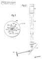
- the apparatus comprises a laser 31 producing a laser beam 24, there being included optical components similar to the lenses 36-38 of the earlier patent application which focus the beam 24 onto a surface 27 to be inspected.
- the surface to be inspected may comprise the surface of a motor car.
- the beam 24 is reflected by means of a mirror 33 to a 8 sided polygon scanner mirror 39 which is rotated by a motor (not shown) at 20,000 RPM to give 2,666 scans per second.
- the scanned part of the beam is passed to an aspheric acrylic lens 43 to collimate the laser beam so that the scan length is constant in any direction from the surface 27 and also so as to allow a smaller retroreflective screen to be used compared with a diverging scan.
- the laser beam 24 is then scanned across the surface 27 and is reflected from the surface 27.
- the light reflected from the surface 27 will comprise two components, a specular component and a diffuse component.
- the specular component leaves surface 27 with a small, substantially zero cone angle but the diffuse component has a large, substantially 180° cone angle.
- the reflected light from surface 27 strikes a retroreflective screen 23 and returns back in the incident direction to be rereflected at the surface 27 and passes through the lens 43 to the scanning drum 39.
- the retroreflective screen will return a beam which is slightly divergent with respect to the beam incident on it so the specular component is reflected as a beam with a small cone angle.
- the beam which has been reflected by the retroreflector 23 and reaches the facet 39A (which is the same facet as reflected the beam on its outward path) is reflected by the facet 39A.
- the beam reflected by the facet 39A will include both the specular component and some of the diffuse light. This beam is thus reflected by the facet 39A along an optical path 101. Because the same facet reflects the beam on its outward path as its inward path the reflected beam will be "descanned" so that movement of the beam caused by rotation of the mirror drum will be removed and thus the optical path 101 of the reflected beam will be parallel to the beam 24 passing between the mirror 33 and the facet 39A. As will be understood, the mirror 33 is small and, therefore, does not interrupt very much of the light passing along light path 101.
- optical path 101 passes a beam which includes substantially all of the specular component and a proportion of the diffuse component of the beam incident on the mirror drum from the surface 27 and all movement of the beam caused by the mirror drum will be removed by reflecting back from the same facet 39A. It will also be understood that the specular component of the light will be polarised whereas the diffuse component will not be polarised.
- the first apparatus comprises a polarising beam splitter 102.
- the polarising beam splitter 102 is arranged so that the polarised specular component of the beam passes straight through the polarising beam splitter 102 whereas some (approximately half) of the diffuse component is reflected by polarising the beam splitter to a lens 103.
- the reflected component passes through the lens 103 onto a filter 104.
- Lens 103 is arranged so as to focus the surface 27 onto the filter 104 so that the filter 104 receives an image of the light beam where it strikes the surface 27.
- Filter 104 is arranged in front of a light collecting means in the form of a fibre optic 106 connected at its remote end to a light detector in the form of a photo cell 94.
- the filter is of the shape shown in Figure 3.
- the filter illustrated in Figure 3 comprises a petal shaped pattern arranged symmetrically about the optical axis 100 of the filter 104.
- the "petals" part 107 is transmissive to the incident radiation and comprises six petals 107A,B,C,D,E,F and the surrounding part 108 is absorptive of the incident radiation.
- the two parts can be transmissive and reflective (see later with respect to filter 122), or reflective and absorptive of the radiation.
- the shape of the two parts 107,108 can be clearly seen from Figure 3, each of said parts 107,108 extending from the optical axis 100.
- each of said parts 107,108 (part 107 comprising the sum of petals 107A-F) has a predetermined arcuate width at each radial distance from the optical axis 100 to provide a predetermined relationship between the diameter of the beam and the amount of radiation passing through the filter.
- the diameter of the beam at the filter 104 can be determined by measuring the amount of light passing through the petal parts 107A-F. If the beam is focused to a small spot on the optical axis 100 of filter 104, then all of the light will pass through the transparent part of the petal parts 107A-F to the fibre optic 106. As the diameter of the beam focused on filter 104 increases then an increasing proportion of the light is absorbed by the opaque part 108 between each petal 107A-F and thus an increasing proportion of the light is lost and not passed to the fibre optic 106.
- the shape of the petals 107A-F is arranged so that the light passed through to the fibre optic 106 is substantially linearly dependent upon the diameter of the beam at the filter 104. In practice we have found a relationship which is linear to ⁇ 5% or even ⁇ 1% relatively easy to achieve, but in some cases ⁇ 20% might be sufficient.
- each of the parts 107,108 has a predetermined arcuate width at each radial distance from the optical axis. This may be provided, for example, by a generally cusp shaped part 107.
- the filter of the invention may be provided by the shape of the front surface of a photodetector or fibre optic 106.
- the front face of the fibre optic 106 may, if desired, be shaped like the part 107, that is it may be petal shaped so as only to collect light from an area corresponding to the petals 107A-F (or any of the alternatives described above) and thus the word "filter” in respect of the claims should be interpreted accordingly, to include the shape of the light collecting face of the fibre optic or of a photodetector.
- Signal A is, therefore, a measure of diffuse light only (back scattered light) directly from the surface 27 which has not passed via the retroreflector 23.
- the outward beam 24 is focused by optical components (not shown) so as to be focused onto surface 27 when the distance between the scanning head and surface 27 is at its optimum distance. If that distance varies, then the image on the surface 27 moves out of focus and so its diameter changes. This is, of course, indicated by signal A, which is proportional to the diameter of the image on the filter 104.
- signal A is a measure of the distance between the lens 43 and surface 27.
- the light reaching the optic fibre 106 is not only dependent upon the diameter of the spot focused on filter 104 but is also dependent upon the actual amount of light in the beam passed to the filter 104 and this can vary depending upon the surface which is being scanned. To eliminate this effect it is necessary to normalise the signal A by comparing the signal A with a signal which is simply dependent upon the diffuse light. This is carried out by comparing signal A with signal F to be described later.
- Filter 113 comprises a clear disc with a matt black centre or may comprise a bundle of separate fibre optics disposed around the matt black centre and being connected to a plurality of remote light sensitive devices 95 or may comprise a plurality of light sensitive devices spaced about a matt black centre.
- Signal B is a measure of movement of the spot of light on the retrorefecting surface 23 which is caused by small defects. If there are small defects on the surface 27 which cause deflection of the beam, then the spot on the retroreflector 23 will be moved. Because the reflected light from the retroreflector 23 has a certain cone angle, if the defect causing the movement of the spot is small compared with the diameter of the beam when it returns from the retroreflector 23 to the surface 27, then the bulk of the light returning from the retroreflector 23 to the surface 27 will not strike the same defect, but will strike an area around that defect and will be reflected back to the lens 43 in a different direction from the incident beam from lens 43 to surface 27.
- Light passing through the annular mirror 111 is passed by a lens 121 onto a filter 122 which is similar to filter 104 except that it includes a matt black centre 125 on its optical axis to absorb the light and the part 108 is of reflective material.
- Lens 121 actually focuses surface 27 onto filter 122.
- Light passing through the transparent petal parts 107 is collected by a lens 123 and focused on a fibre optic 124 connected at its remote end to a light sensitive device 96 which provides a signal C.
- Light reflected from the reflective part 108 is collected by a lens 126 and focused on a fibre optic 127 having a light sensitive device 97 remotely connected thereto to provide a signal D.
- lens 121 focuses the surface 27 onto the filter 122 and because the diffuse light originates from the surface 27, all of the diffuse light is therefore focused to a central point on the filter 122 and is eliminated by the matt black central spot.
- specular light is received by the outer part of the filter 122 and is either passed through to fibre optic 124 or is reflected to fibre optic 127 to produce signals C and D respectively.
- the sum of signals C and D therefore provides a measure of the total specular light.
- Signal C will indicate the diameter of the spot of specular light incident on the filter 122 and this provides measurements of subtle changes of the shape of the surface 27.
- the surface 27 will act as an active optical component either focusing or defocusing the slightly divergent beam of light which is reflected from the retroreflector 23 to the surface 27.
- the signals C and D we provide a measure of the diameter of the image at filter 122 which in turn is an indication of the curvature and hence the optical power of the surface 27. This measurement is particularly useful, since it will measure very shallow dents on near flat panels which are otherwise difficult to detect.
- diffuse light is reflected from the surface 27 through a cone angle of 180° and, therefore, some of this diffuse light will pass back and reach the facet 39B adjacent to the facet 39A.
- a small amount of specular light will also reach facet 39B.
- the light received by facet 39B is reflected along an optical path 131.
- the optical path 131 is substantially stationary and it is "descanned" in the same way as optical path 101.
- the facets 39A and 39B are not in exactly the same position there is some slight movement of the optical path 131.
- Light on the optical path 131 passes to a polarising beam splitter 132.
- Light reflected by the polarising beam splitter 132 is collected and focused by lens 133 and focused onto a slit 136, light passing through the slit 136 being collected by a fibre optic 137 connected at its remote end to a light sensitive device 98to provide a signal E.
- the lens 133 focuses an image of the retroreflectors surface 23 onto the slit 136.
- the signal E is a measurement of a characteristic of the surface 27 which is referred to as "distinctness of image" (DOI). This is essentially how clear the image of an object appears when viewed via the surface 27 and is of interest in respect of painted surfaces such as motor cars.
- DOI distinctness of image
- the image of the retroreflector 23 on the filter 136 will move slightly during each scan and hence will slowly scan across the slit 136.
- two images reach the slit 136, a first focused image of the beam at the retroreflector surface 23 and a second image of the beam at the surface 27. These two images are separated spatially and signal E relates only to the scanning of the image of the beam on the retroreflector surface 23 across the slit.
- the DOI can be measured as the sharpness of the signal edges when compared with the width of the spot (in other words a measure of the degree of fuzziness of the edge of the spot).
- An analysis of the signal E during a scan will produce a measurement of this fuzziness and hence the DOI.
- Light passing through the polarising beam splitter 132 is focused by a lens 141 directly onto a fibre optic 142 the remote end of which is connected to a light sensitive device 99 to provide a signal F.
- signal F is a direct measure of the diffuse light.
- signal F provides a normalisation signal.
- signal A will vary because the total amount of light striking the filter 104 will vary, but this effect can be removed by comparing signal A with signal F which will also vary in the same way.
- a combination of signals A and F (for example the ratio of signals A to F) will provide a measure of the distance between the scanning head and the surface 27.
- the rate of change of this range can be used to provide a measure of surface curvature.
- Changes in the level of signal F can be used to indicate diffuse defects such as changes of surface colour. On very steeply curved surfaces where no specular return can be obtained from the retroreflective screen 23 (ie the beam from the surface 27 misses the screen 23) severe surface defects can be detected.
- Summing signals C and D provides an indication of surfaces defects such as dinks, dirt nibs, and low gloss.
- Signal B measures surface defects such as "orange peel” or scratches or digs.
- Signal E measures the distinctiveness of image (DOI).
- a bundle 100 of fibre optics may be provided.
- the opposite ends of the fibre optics 100 may be arranged to pass light to the various detectors which produce signals A to F whereby to compensate for variations in the laser light level or sensitivity of the light detectors.
Landscapes
- Physics & Mathematics (AREA)
- General Physics & Mathematics (AREA)
- General Health & Medical Sciences (AREA)
- Textile Engineering (AREA)
- Life Sciences & Earth Sciences (AREA)
- Chemical & Material Sciences (AREA)
- Analytical Chemistry (AREA)
- Biochemistry (AREA)
- Engineering & Computer Science (AREA)
- Health & Medical Sciences (AREA)
- Immunology (AREA)
- Pathology (AREA)
- Optics & Photonics (AREA)
- Spectroscopy & Molecular Physics (AREA)
- Investigating Materials By The Use Of Optical Means Adapted For Particular Applications (AREA)
- Length Measuring Devices By Optical Means (AREA)
Applications Claiming Priority (2)
| Application Number | Priority Date | Filing Date | Title |
|---|---|---|---|
| GB868621418A GB8621418D0 (en) | 1986-09-05 | 1986-09-05 | Inspection apparatus |
| GB8621418 | 1986-09-05 |
Publications (2)
| Publication Number | Publication Date |
|---|---|
| EP0259036A2 true EP0259036A2 (de) | 1988-03-09 |
| EP0259036A3 EP0259036A3 (de) | 1989-06-28 |
Family
ID=10603726
Family Applications (1)
| Application Number | Title | Priority Date | Filing Date |
|---|---|---|---|
| EP87307157A Withdrawn EP0259036A3 (de) | 1986-09-05 | 1987-08-13 | Apparat zur Qualitätsprüfung |
Country Status (3)
| Country | Link |
|---|---|
| US (1) | US4861164A (de) |
| EP (1) | EP0259036A3 (de) |
| GB (1) | GB8621418D0 (de) |
Cited By (1)
| Publication number | Priority date | Publication date | Assignee | Title |
|---|---|---|---|---|
| WO1994012867A1 (en) * | 1992-11-24 | 1994-06-09 | Estek Corporation | Particle detection system with coincident detection |
Families Citing this family (20)
| Publication number | Priority date | Publication date | Assignee | Title |
|---|---|---|---|---|
| US5157589A (en) * | 1990-07-02 | 1992-10-20 | General Electric Company | Mutliple lamination high density interconnect process and structure employing thermoplastic adhesives having sequentially decreasing TG 's |
| US5095204A (en) * | 1990-08-30 | 1992-03-10 | Ball Corporation | Machine vision inspection system and method for transparent containers |
| US5153445A (en) * | 1991-07-22 | 1992-10-06 | General Motors Corporation | Method and apparatus for measuring orange peel and texture in painted surfaces |
| US5155372A (en) * | 1991-11-26 | 1992-10-13 | International Business Machines Corporation | Optical inspection system utilizing wedge shaped spatial filter |
| US5426509A (en) * | 1993-05-20 | 1995-06-20 | Peplinski; Robert A. | Device and method for detecting foreign material on a moving printed film web |
| US6271916B1 (en) * | 1994-03-24 | 2001-08-07 | Kla-Tencor Corporation | Process and assembly for non-destructive surface inspections |
| US5831725A (en) * | 1996-10-16 | 1998-11-03 | Atlas Electric Devices Co. | Two-mode surface defect testing system |
| US5917589A (en) * | 1997-04-28 | 1999-06-29 | International Business Machines Corporation | Surface inspection tool |
| US5969370A (en) * | 1997-04-28 | 1999-10-19 | International Business Machines Corporation | Surface inspection tool |
| US5847823A (en) * | 1997-04-28 | 1998-12-08 | International Business Machines Corporation | Surface inspection tool |
| US6100971A (en) * | 1997-04-28 | 2000-08-08 | International Business Machines Corporation | Surface inspection tool |
| US6624884B1 (en) | 1997-04-28 | 2003-09-23 | International Business Machines Corporation | Surface inspection tool |
| US5867261A (en) * | 1997-04-28 | 1999-02-02 | International Business Machines Corporation | Surface inspection tool |
| US6704435B1 (en) | 1997-04-28 | 2004-03-09 | International Business Machines Corporation | Surface inspection tool |
| US6201601B1 (en) | 1997-09-19 | 2001-03-13 | Kla-Tencor Corporation | Sample inspection system |
| US6956644B2 (en) * | 1997-09-19 | 2005-10-18 | Kla-Tencor Technologies Corporation | Systems and methods for a wafer inspection system using multiple angles and multiple wavelength illumination |
| US20040057045A1 (en) * | 2000-12-21 | 2004-03-25 | Mehdi Vaez-Iravani | Sample inspection system |
| US5898492A (en) * | 1997-09-25 | 1999-04-27 | International Business Machines Corporation | Surface inspection tool using reflected and scattered light |
| US20050134841A1 (en) * | 1998-09-18 | 2005-06-23 | Mehdi Vacz-Iravani | Sample inspection system |
| DE10102387C1 (de) * | 2001-01-19 | 2002-05-29 | Atlas Mat Testing Tech Gmbh | Verfahren zur Feststellung und Bewertung von Defekten einer Probenoberfläche |
Family Cites Families (8)
| Publication number | Priority date | Publication date | Assignee | Title |
|---|---|---|---|---|
| GB1535507A (en) * | 1975-11-24 | 1978-12-13 | Secr Defence | Light beam measurement |
| US4314760A (en) * | 1979-08-27 | 1982-02-09 | Trw Inc. | Optical sensing device |
| JPS5646433A (en) * | 1979-09-25 | 1981-04-27 | Nec Corp | Measuring device of laser beam diameter |
| JPS57131039A (en) * | 1981-02-07 | 1982-08-13 | Olympus Optical Co Ltd | Defect detector |
| US4629319A (en) * | 1984-02-14 | 1986-12-16 | Diffracto Ltd. | Panel surface flaw inspection |
| GB8424084D0 (en) * | 1984-09-24 | 1984-10-31 | Sira Ltd | Inspection apparatus |
| IT1179877B (it) * | 1984-12-18 | 1987-09-16 | Cselt Centro Studi Lab Telecom | Procedimento e apparecchiatura per la misura del profilo d indice di rifrazione di fibre ottiche monomodo |
| JPS61248790A (ja) * | 1985-04-26 | 1986-11-06 | Ricoh Co Ltd | 熱転写記録媒体 |
-
1986
- 1986-09-05 GB GB868621418A patent/GB8621418D0/en active Pending
-
1987
- 1987-08-13 EP EP87307157A patent/EP0259036A3/de not_active Withdrawn
-
1988
- 1988-11-10 US US07/271,396 patent/US4861164A/en not_active Expired - Fee Related
Cited By (2)
| Publication number | Priority date | Publication date | Assignee | Title |
|---|---|---|---|---|
| WO1994012867A1 (en) * | 1992-11-24 | 1994-06-09 | Estek Corporation | Particle detection system with coincident detection |
| US5329351A (en) * | 1992-11-24 | 1994-07-12 | Estek Corporation | Particle detection system with coincident detection |
Also Published As
| Publication number | Publication date |
|---|---|
| US4861164A (en) | 1989-08-29 |
| EP0259036A3 (de) | 1989-06-28 |
| GB8621418D0 (en) | 1986-10-15 |
Similar Documents
| Publication | Publication Date | Title |
|---|---|---|
| US4861164A (en) | Apparatus for separating specular from diffuse radiation | |
| US4378159A (en) | Scanning contaminant and defect detector | |
| EP0416067B1 (de) | Verfahren und vorrichtung zur analyse der teilchengrösse | |
| US5661556A (en) | System for measuring the total integrated scatter of a surface | |
| KR20010040931A (ko) | 레이저 스캐너 측정 시스템 | |
| CA1259390A (en) | Inspection apparatus | |
| US4806018A (en) | Angular reflectance sensor | |
| EP0178037B1 (de) | Kompaktes Laserabtastgerät | |
| JPH0695075B2 (ja) | 表面性状検出方法 | |
| CA1135971A (en) | Radiant energy reradiating flow cell system and method | |
| US4306813A (en) | Apparatus for determining faults in strip material | |
| US4728196A (en) | Arrangement for determining a surface structure, especially for roughness | |
| US5365343A (en) | Light flux determination of particle contamination | |
| KR0125442B1 (ko) | 표면 거칠기 광탐지 방법 및 장치 | |
| US4116566A (en) | Line scanning device for detecting defects in webs of material | |
| US4259013A (en) | Optical method for inspecting spherical parts | |
| US4248537A (en) | Optical apparatus for determining the light exit angle from a material strip illuminated by a light bead | |
| JP2004000004U (ja) | 表面計測のためのプローブ | |
| JP2004000004U6 (ja) | 表面計測のためのプローブ | |
| US4295743A (en) | Apparatus for determining faults in strip material | |
| JP3646063B2 (ja) | 技術的表面における小さな周期的うねりを検出および測定するための装置 | |
| GB2118304A (en) | Detecting surface deviations | |
| EP0244102B1 (de) | Vorrichtung zur Güteprüfung | |
| JPS5960344A (ja) | 表面をコヒ−レントレ−ザ光束で自動的に検査する方法および装置 | |
| JPH07209169A (ja) | 浮遊粒子群の濃度と粒度の空間分布の測定方法と装置 |
Legal Events
| Date | Code | Title | Description |
|---|---|---|---|
| PUAI | Public reference made under article 153(3) epc to a published international application that has entered the european phase |
Free format text: ORIGINAL CODE: 0009012 |
|
| AK | Designated contracting states |
Kind code of ref document: A2 Designated state(s): BE DE ES FR GB IT NL SE |
|
| PUAL | Search report despatched |
Free format text: ORIGINAL CODE: 0009013 |
|
| AK | Designated contracting states |
Kind code of ref document: A3 Designated state(s): BE DE ES FR GB IT NL SE |
|
| 17P | Request for examination filed |
Effective date: 19890817 |
|
| 17Q | First examination report despatched |
Effective date: 19900308 |
|
| STAA | Information on the status of an ep patent application or granted ep patent |
Free format text: STATUS: THE APPLICATION IS DEEMED TO BE WITHDRAWN |
|
| 18D | Application deemed to be withdrawn |
Effective date: 19911001 |
|
| RIN1 | Information on inventor provided before grant (corrected) |
Inventor name: WEST, ROBERT NOEL |