EP0259115B1 - Verfahren und Vorrichtung zur Verminderung der N0x-Emission aus katalytischen Wirbelschichtspaltungsanlagen - Google Patents
Verfahren und Vorrichtung zur Verminderung der N0x-Emission aus katalytischen Wirbelschichtspaltungsanlagen Download PDFInfo
- Publication number
- EP0259115B1 EP0259115B1 EP19870307640 EP87307640A EP0259115B1 EP 0259115 B1 EP0259115 B1 EP 0259115B1 EP 19870307640 EP19870307640 EP 19870307640 EP 87307640 A EP87307640 A EP 87307640A EP 0259115 B1 EP0259115 B1 EP 0259115B1
- Authority
- EP
- European Patent Office
- Prior art keywords
- catalyst
- regenerator
- bed
- flue gas
- stream
- Prior art date
- Legal status (The legal status is an assumption and is not a legal conclusion. Google has not performed a legal analysis and makes no representation as to the accuracy of the status listed.)
- Expired
Links
Images


Classifications
-
- C—CHEMISTRY; METALLURGY
- C10—PETROLEUM, GAS OR COKE INDUSTRIES; TECHNICAL GASES CONTAINING CARBON MONOXIDE; FUELS; LUBRICANTS; PEAT
- C10G—CRACKING HYDROCARBON OILS; PRODUCTION OF LIQUID HYDROCARBON MIXTURES, e.g. BY DESTRUCTIVE HYDROGENATION, OLIGOMERISATION, POLYMERISATION; RECOVERY OF HYDROCARBON OILS FROM OIL-SHALE, OIL-SAND, OR GASES; REFINING MIXTURES MAINLY CONSISTING OF HYDROCARBONS; REFORMING OF NAPHTHA; MINERAL WAXES
- C10G11/00—Catalytic cracking, in the absence of hydrogen, of hydrocarbon oils
- C10G11/14—Catalytic cracking, in the absence of hydrogen, of hydrocarbon oils with preheated moving solid catalysts
- C10G11/18—Catalytic cracking, in the absence of hydrogen, of hydrocarbon oils with preheated moving solid catalysts according to the "fluidised-bed" technique
- C10G11/182—Regeneration
Definitions
- This invention relates to a process for regenerating fluidized cracking catalyst.
- the hydrocarbon conversion catalyst usually employed in a fluid catalytic cracking (FCC) installation is preferably a high activity crystalline zeolite catalyst of a fluidizable particle size.
- the catalyst is transferred in suspended or dispersed phase condition generally upwardly through one or more riser conversion zones (fluid catalytic cracking zones), providing a hydrocarbon residence time in each conversion zone in the range of 0.5 to about 10 seconds, and usually less than about 8 seconds.
- High temperature risers and 0.5 to 4 seconds hydrocarbon residence time in the riser may be used to make cracked products.
- U. S. Patent No. 4,336,160 to Dean et al attempts to reduce hydrothermal degradation by staged regeneration.
- the first stage of the regeneration process of Dean et al employs a dense bed which provides an opportunity for hydrothermal deactivation.
- a major trend in fluid catalytic cracking processing has been modifications to the process to permit it to accommodate a wider variety of feedstocks, in particular, stocks that contain more nitrogen than had previously been permitted in a feed to a fluid catalytic cracking unit.
- U. S. Patent No. 4,325,833 to Scott discloses a three-stage regenerator directed to NO x removal. Scott discloses that his middle stage contains a substantially oxygen-free atmosphere to convert NO x to N2. However, flue gas from lower beds contact with catalyst from upper beds. This is detrimental because the flue gas contains water which can deactivate the catalyst by hydrothermal degradation.
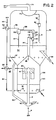
- Fig. 1 shows FCC regenerator, which regenerates spent catalyst stream 2, from an FCC reactor (not shown).
- the spent catalyst is conventional. Preferably it comprises intermediate pore zeolite catalyst, most preferably ZSM-5 and a large pore zeolite such as zeolite Y.
- the spent catalyst combines with a first airstream 4, and preferably a regenerated recycle catalyst 52 from an optional standpipe 50, to form a mixture.
- the mixture passes through a first regenerator riser 6.
- the mixture passes through riser 6 in plug flow at 538° to 677°C (1000° and 1250°F).
- Enough air is added via line 4 to sustain combustion at the inlet and partly through the riser 6. This burns off coke and forms H2O and NO x .
- the oxygen concentration varies along the riser 6.
- the spent catalyst initially combines with airstream 4
- the initial oxygen concentration is sufficiently high to promote combustion.
- the oxygen concentration lessens sufficiently to shift equilibrium, denoted by the following reaction, to convert NO x , produced during combustion, to N2: 2NO x ⁇ N2 + xO2
- the mixture is oxygen-lean, preferably having an oxygen concentration between 0 and 1 mole %, most preferably between 0 and 0.5 mole %, when it exits the riser 6. This converts a portion of the NO x to N2 prior to exiting the riser 6.
- the mixture is discharged from the first riser 6 and passes into a plurality of discharge arms 14 which impart downward momentum to the mixture.
- the discharge arms 14 are housed within a riser cover 20.
- first flue gas stream 22 After exiting the discharge arms 14, flue gas is removed as a first flue gas stream 22.
- the catalyst from the mixture continues down into the first catalyst bed 16, located in a lower portion 10 of a second regenerator riser 8.
- Riser 8 is a fast fluid bed riser.
- a fast fluid bed riser is disclosed in U. S. Patent No. 4,444,722 to Owen.
- the lower portion 10 has a larger inside diameter than an attached upper portion 12.
- a second airstream 18 passes through a header 19 into the first catalyst bed 16 to promote further regeneration.
- Stream 18 may be preheated by indirect heat exchange with the first flue gas stream 22 in a heat exchanger 24.
- the amount of air passed into the first catalyst bed 16 is preferably just enough to sustain combustion in the bed 16 and partly through the second riser 8.
- the mixture is sufficiently oxygen-lean to shift equilibrium to favor converting NO x to N2.
- oxygen concentration is 0 to 1 mole %, most preferably 0 to 0.5 mole % as gas exits the riser 8. This converts a portion of the NO x to N2 prior to exiting the second riser 8.
- Bed 16 is preferably 28°C (50°F) or more hotter than the riser 6 exit, but not above 704°C (1300°F).
- the airstream 18 and combustion products formed in bed 16 elutriate a first catalyst stream 26 up from first bed 16 into the upper portion 12 of the second regeneration riser 8.
- a second catalyst stream can be withdrawn from bed 16 through an optional conduit 17 and sent to a fluid catalytic cracking reactor (not shown).
- the catalyst stream 26 passes through upper portion 12, which is located within a catalyst collecting chamber 30. Stream 26 discharges from upper portion 12 into a plurality of discharge arms 32 which impart downward momentum to the stream 26.
- the discharge arms 32 are housed within a riser cover 38.
- the downwardly directed catalyst countercurrently contacts combustion gases from a second catalyst bed 34 located therebelow. The combustion gases displace gaseous material upwardly and away from the downwardly directed catalyst. The displaced gases form a second flue gas stream 40 which exits the chamber 30 and indirectly preheats an airstream 44 in indirect heat exchanger 42.
- the catalyst continues downwardly to the second catalyst bed 34.
- a third airstream 36 passes through a header 37 into the second bed 34 to contact catalyst in bed 34.
- Bed 34 is preferably at least 14°C (25°F) hotter than bed 16 but below 871°C (1600°F).
- Some hot regenerated catalyst is preferably withdrawn from bed 34 via standpipe 50 and recycled to mix with spent catalyst stream 2, as discussed above.
- Regenerated catalyst is withdrawn from bed 34 via conduit 54 and passed to a fluid catalytic cracking reactor (not shown).
- Combustion gases from second bed 34 which do not exit with second flue gas stream 40, pass up through the collecting chamber 30 to a cyclone 60, which separates gas from entrained catalyst and discharges gas via conduit 62, plenum chamber 70 and conduit 74 as a third flue gas stream 72.
- a number of cyclones, such as cyclone 60, in series or parallel, or both, may be provided within chamber 30. Catalyst recovered by cyclone 60 returns to second catalyst bed 34 through dipleg 61.
- the catalyst comprises some intermediate pore zeolites catalyst, such as ZSM-5, or particles comprising large pore zeolite catalysts, such as zeolite Y. It is desirable to subject the larger pore zeolite catalysts to more regeneration than the intermediate pore zeolite catalysts, because the larger pore zeolite catalysts tend to deactivate with coke more readily than the intermediate pore zeolite catalysts.
- the catalyst stream 26 discharges from the upper portion 112 into a riser cyclone inlet conduit 114 to a riser cyclone 120.
- the gas from riser cyclone 120 discharges via conduit 128 to cyclone 130 via conduit 122.
- Cyclone 130 may be attached to downstream cyclones (not shown) by a conventional enclosed conduit (not shown).
- the riser cyclone overhead conduit 122 includes a lower vertical conduit 124, attached to the cyclone 120, which is inserted into an upper vertical conduit 126. Conduit 126 is attached to cyclone inlet conduit 128.
- the annulus between conduit 124 and conduit 126 admits gas from catalyst bed 34. Preferably, the annulus is sized such that the gas velocity in it is between 1.5 and 30 m/s (5 and 100 feet per second). Catalyst recovered by cyclones 120 and 130 passed through diplegs 121, 131 to the second catalyst bed 34.
- Combustion gases from bed 34 which do not exit as part of the second flue gas stream pass into one or more cyclones 60 and exit through overhead conduit 62 to plenum chamber 70 and through the withdrawal conduit 74 as a third flue gas stream 72.
- Catalyst separated in cyclone 60 returns to the second catalyst bed 34 through a dipleg 61.
- the risers 6, 108 operate at oxygen-lean conditions.
- the first and second airstreams 4, 18 preferably supply enough air so that the mixtures exiting the first riser 6 and fast fluid bed riser 108 comprise gas having an oxygen concentration between 0 and 1 mole %, most preferably between 0 and 0.5 mole %.
- Exiting the first riser 6 is defined as when the mixture passes into discharge arms 14.
- Exiting the fast fluid bed riser is defined as when the mixture passes out of riser upper portion 112 into conduit 114.
- Airstream 36 preferably provides the minimum amount of air necessary to sustain combustion to bed 34.
- the riser cyclone overhead conduit 152 includes a lower vertical conduit 154, attached to the cyclone 150, which is inserted into an upper vertical conduit 156. Conduit 156 is in turn attached to a primary cyclone inlet conduit 158. An annulus is formed between conduit 154 and conduit 156 so that a portion of gas from catalyst bed 16 may pass into upper conduit 156. Preferably, the annulus is sized such that the velocity of the gas into the annulus is between 1.5 and 30 m/s (5 and 100 feet per second). Catalyst separated in cyclones 150 and 160 passes through diplegs 151, 161 to the first catalyst bed 16.
- the risers 142, 108 operate at oxygen-lean conditions.
- the first and second airstream 4, 18 preferably supply enough air so that the mixtures exiting the first riser 142 and fast fluid bed riser 108 comprise gas having an oxygen concentration between 0 and 1 mole %, most preferably between 0 and 0.5 mole %.
- the first riser 142 exit is the cyclone inlet conduit 144.
- the bed 108 exit is at the entrance to conduit 114.
- Airstream 36 preferably provides the minimum amount of air necessary to sustain combustion in bed 34.
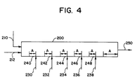
- the mixture passes through the conduit 200 and sequentially contacts the plurality of oxygen-containing airstreams 230, 232, 234, 236, 238 at regenerating conditions.
- the oxygen concentration varies along conduit 200.
- the catalyst initially contacts the airstreams 212, 230, 232, 234, 236, 238, the initial oxygen concentration is sufficiently high to promote combustion. Then, as combustion continues, the oxygen is depleted so that the mixture passes through a region A of relatively lower oxygen concentration.
- the oxygen concentration in the region A is sufficiently low to shift equilibrium, denoted by the following reaction to convert NO x , produced during regeneration, to N2: NO x ⁇ N2 + xO
- a regenerated mixture 250 then exits the conduit 200 and passes to a cyclone, or other gas-solid separation device (not shown), to separate into a flue gas stream and a regenerated catalyst stream.
- the regenerated catalyst may then undergo further regeneration or pass to a fluid catalytic cracking reactor (not shown) for combination with fluid catalytic cracking hydrocarbon feed. Further regeneration may occur by recycling, the separated catalyst to conduit 200, or in subsequent regenerator stages.
- the conduit 200 may substitute for riser 6 of Figs. 1 and 2, or riser 142 of Fig. 3.
- the first, second and third embodiments of the present invention have the advantage that regenerating fluid catalytic cracking catalyst in stages, and quickly removing flue gas from the catalyst in each stage, minimizes hydrothermal degradation and minimizes NO x formation.
- the fourth embodiment provides multistage regeneration, to reduce NO x , in a single transport conduit. This is particularly useful in retrofitting FCC regenerators.
Landscapes
- Chemical & Material Sciences (AREA)
- Oil, Petroleum & Natural Gas (AREA)
- Engineering & Computer Science (AREA)
- Chemical Kinetics & Catalysis (AREA)
- General Chemical & Material Sciences (AREA)
- Organic Chemistry (AREA)
- Production Of Liquid Hydrocarbon Mixture For Refining Petroleum (AREA)
- Catalysts (AREA)
Claims (9)
- Verfahren zur Regenerierung eines mit Koks verunreinigten Katalysators im Wirbelschichtbett durch Kombination eines Stroms des verkokten Katalysators mit einem Strom von heißem regeneriertem Katalysator und einem ersten sauerstoffhaltigen Gasstrom, um eine erste Mischung aus Katalysator und Gas zu bilden, und Regenerierung des Katalysators durch Abbrennen des Kokses, gekennzeichnet durch:
Leiten dieser Mischung durch einen Regenerator der ersten Stufe, der einen ersten Regenerator-Riser mit einem oberen und einem unteren Ende umfaßt, und Beibehaltung einer geringen Sauerstoffkonzentration im oberen Ende des Risers, um einen Strom aus Katalysator und erstem Abgas zu bilden;
Abgabe des Stroms aus Katalysator und Abgas aus dem Riser und Trennung des Stroms aus Katalysator und Abgas in einen mit Katalysator angereicherten Strom, der nach unten abgegeben wird, um ein erstes Katalysatorbett, das im unteren Abschnitt des Regenerators der zweiten Stufe angeordnet ist, und einen ersten Abgasstrom aus dem Regenerator zu bilden;
Zugabe eines zweiten sauerstoffhaltigen Stroms zum ersten Katalysatorbett, um eine zweite Mischung aus Katalysator und Gas zu bilden, die zum oberen Abschnitt des Regenerators der zweiten Stufe strömt, und Beibehaltung einer geringen Sauerstoffkonzentration im oberen Abschnitt des Regenerators der zweiten Stufe;
Abgabe des Katalysators mit reduziertem Koksgehalt und des Abgases vom oberen Abschnitt des Regenerators der zweiten Stufe und Abtrennung des Katalysators mit reduziertem Koksgehalt vom Abgas und Bildung eines zweiten Katalysatorbettes und eines zweiten Abgasstroms, Entfernung sowohl des ersten als auch des zweiten Abgasstroms aus den Regeneratoren der ersten und zweiten Stufe;
Rezirkulierung des heißen regenerierten Katalysatorstroms vom zweiten Bett zum Regenerator der ersten Stufe. - Verfahren nach Anspruch 1, weiterhin gekennzeichnet durch:
Abtrennung eines Abgasstroms vom Katalysator und Abgas vom Regenerator der zweiten Stufe, um einen mit Katalysator angereicherten Strom zu gewinnen, der abgegeben wird, um ein zweites Katalysatorbett zu bilden, das im Regenerator der dritten Stufe angeordnet ist;
Zugabe eines dritten sauerstoffhaltigen Stroms zum Katalysator im zweiten Bett, um die Katalysatorregenerierung abzuschließen;
Abziehen des Abgasstroms oberhalb des zweiten Bettes. - Verfahren nach Anspruch 1 oder 2, weiterhin dadurch gekennzeichnet, daß der Strom durch den ersten Riser eine ideale Strömung ist und das aus dem Riser abgegebene Gas weniger als 1 Mol-% molekularen Sauerstoff aufweist.
- Verfahren nach einem der vorstehenden Ansprüche, weiterhin durch eine ideale Strömung der zweiten Mischung durch den oberen Abschnitt des Regenerators der zweiten Stufe, eine Gasverweilzeit von 1 bis 20 s im Regenerator der zweiten Stufe gekennzeichnet, wobei das davon abgegebene Gas weniger als 1 Mol-% molekularen Sauerstoff aufweist.
- Verfahren nach einem der vorstehenden Ansprüche, weiterhin dadurch gekennzeichnet, daß die Temperatur im ersten Regenerator-Riser 538° bis 677°C (1000° bis 1250°F) beträgt, das erste Bett mindestens 28°C wärmer, jedoch 704°C (1300°F) nicht übersteigt, und das zweite Bett mindestens 14°C wärmer als das erste Bett ist, jedoch 871°C (1600°F) nicht übersteigt, und das von jeder Stufe des Regenerators abgegebene Gas weniger als 1,0 Mol-% Sauerstoff aufweist.
- Verfahren nach einem der vorstehenden Ansprüche, weiterhin dadurch gekennzeichnet, daß das aus jeder Stufe des Regenerators abgegebene Gas weniger als 0,5 Mol-% Sauerstoff aufweist.
- Verfahren nach einem der vorstehenden Ansprüche, weiterhin dadurch gekennzeichnet, daß die von zumindest einer Stufe des Regenerators abgegebene Mischung durch Kontakt mit einer ersten Vielzahl von Armen nach unten gerichtet wird, die sich von der Ausgabeseite radial erstrecken, wobei sich diese Arme in einer Abdeckung befinden.
- Verfahren nach einem der vorstehenden Ansprüche, weiterhin dadurch gekennzeichnet, daß die von zumindest einer Stufe des Regenerators abgegebene Mischung direkt in einen Zyklon gegeben wird, der das Abgas vom Katalysator trennt.
- Verfahren nach einem der vorstehenden Ansprüche, weiterhin dadurch gekennzeichnet, daß zumindest ein Teil der sauerstoffhaltigen Ströme durch indirekten Wärmeaustausch mit zumindest einem Abgasstrom erwärmt wird.
Applications Claiming Priority (2)
| Application Number | Priority Date | Filing Date | Title |
|---|---|---|---|
| US90334486A | 1986-09-03 | 1986-09-03 | |
| US903344 | 1986-09-03 |
Publications (3)
| Publication Number | Publication Date |
|---|---|
| EP0259115A2 EP0259115A2 (de) | 1988-03-09 |
| EP0259115A3 EP0259115A3 (en) | 1989-01-18 |
| EP0259115B1 true EP0259115B1 (de) | 1992-07-01 |
Family
ID=25417347
Family Applications (1)
| Application Number | Title | Priority Date | Filing Date |
|---|---|---|---|
| EP19870307640 Expired EP0259115B1 (de) | 1986-09-03 | 1987-08-28 | Verfahren und Vorrichtung zur Verminderung der N0x-Emission aus katalytischen Wirbelschichtspaltungsanlagen |
Country Status (4)
| Country | Link |
|---|---|
| EP (1) | EP0259115B1 (de) |
| JP (1) | JPS6372352A (de) |
| CA (1) | CA1296700C (de) |
| DE (1) | DE3780103D1 (de) |
Families Citing this family (2)
| Publication number | Priority date | Publication date | Assignee | Title |
|---|---|---|---|---|
| US4814068A (en) * | 1986-09-03 | 1989-03-21 | Mobil Oil Corporation | Fluid catalytic cracking process and apparatus for more effective regeneration of zeolite catalyst |
| US5183558A (en) * | 1990-12-31 | 1993-02-02 | Mobil Oil Corporation | Heavy oil catalytic cracking process and apparatus |
Family Cites Families (1)
| Publication number | Priority date | Publication date | Assignee | Title |
|---|---|---|---|---|
| US4116814A (en) * | 1977-07-18 | 1978-09-26 | Mobil Oil Corporation | Method and system for effecting catalytic cracking of high boiling hydrocarbons with fluid conversion catalysts |
-
1987
- 1987-08-28 EP EP19870307640 patent/EP0259115B1/de not_active Expired
- 1987-08-28 DE DE8787307640T patent/DE3780103D1/de not_active Expired - Lifetime
- 1987-09-02 CA CA000545978A patent/CA1296700C/en not_active Expired - Lifetime
- 1987-09-02 JP JP22117287A patent/JPS6372352A/ja active Pending
Also Published As
| Publication number | Publication date |
|---|---|
| JPS6372352A (ja) | 1988-04-02 |
| EP0259115A3 (en) | 1989-01-18 |
| DE3780103D1 (de) | 1992-08-06 |
| EP0259115A2 (de) | 1988-03-09 |
| CA1296700C (en) | 1992-03-03 |
Similar Documents
| Publication | Publication Date | Title |
|---|---|---|
| US4283273A (en) | Method and system for regenerating fluidizable catalyst particles | |
| EP0539529B1 (de) | Verfahren zur steuerung der mehrstufigen katalysatorregenerierung mit mit partieller co-verbrennung | |
| US5582712A (en) | Downflow FCC reaction arrangement with upflow regeneration | |
| JP2523325B2 (ja) | 新規な下降流の流動化接触分解反応器 | |
| EP0106052B1 (de) | Entmetallisierung und Entkarbonisierung schwerer Rückstandsöl-Einsatzprodukte | |
| US4789458A (en) | Fluid catalytic cracking with plurality of catalyst stripping zones | |
| EP0142275B1 (de) | Verfahren zum katalytischen Cracken mit hoher Verweilzeit | |
| US4988430A (en) | Supplying FCC lift gas directly from product vapors | |
| US4814068A (en) | Fluid catalytic cracking process and apparatus for more effective regeneration of zeolite catalyst | |
| US4793915A (en) | Short contact time fluid catalytic cracking process | |
| US4118338A (en) | Method for regenerating a fluid cracking catalyst | |
| US4036779A (en) | Method of regenerating catalyst in a swirl type regenerator containing a dilute phase baffle | |
| WO1992001632A1 (en) | Process for control of multistage catalyst regeneration with full then partial co combustion | |
| US5059302A (en) | Method and apparatus for the fluid catalytic cracking of hydrocarbon feed employing a separable mixture of catalyst and sorbent particles | |
| US3846280A (en) | Method of improving a dense fluid bed catalyst regenerator used in conjunction with a riser hydrocarbon conversion operation | |
| US3923686A (en) | Fluidized catalyst regeneration by oxidation in a dense phase bed and a dilute phase transport riser | |
| US3970587A (en) | Combustion regeneration of hydrocarbon conversion catalyst with recycle of high temperature regenerated catalyst | |
| EP0493932B1 (de) | Verfahren und Apparat für das katalytische Kracken von Schweröl | |
| US4444722A (en) | System for regenerating fluidizable catalyst particles | |
| US4853187A (en) | Apparatus to reduce NOx emissions from a fluid catalytic cracking unit | |
| US4738829A (en) | Apparatus for spent catalyst treating for fluidized catalytic cracking systems | |
| EP0236054A2 (de) | Verfahren zur Behandlung von Kohlenwasserstoffen | |
| EP0490453A1 (de) | Verfahren und Apparat zur Beseitigung von Kohlenstoffmaterialien von Feststoffteilchen | |
| US4428822A (en) | Fluid catalytic cracking | |
| US4868144A (en) | Process to reduce NOx emissions from a fluid catalytic cracking unit |
Legal Events
| Date | Code | Title | Description |
|---|---|---|---|
| PUAI | Public reference made under article 153(3) epc to a published international application that has entered the european phase |
Free format text: ORIGINAL CODE: 0009012 |
|
| AK | Designated contracting states |
Kind code of ref document: A2 Designated state(s): BE DE FR GB IT NL |
|
| PUAL | Search report despatched |
Free format text: ORIGINAL CODE: 0009013 |
|
| AK | Designated contracting states |
Kind code of ref document: A3 Designated state(s): BE DE FR GB IT NL |
|
| 17P | Request for examination filed |
Effective date: 19890608 |
|
| 17Q | First examination report despatched |
Effective date: 19900917 |
|
| GRAA | (expected) grant |
Free format text: ORIGINAL CODE: 0009210 |
|
| AK | Designated contracting states |
Kind code of ref document: B1 Designated state(s): BE DE FR GB IT NL |
|
| PG25 | Lapsed in a contracting state [announced via postgrant information from national office to epo] |
Ref country code: IT Free format text: LAPSE BECAUSE OF FAILURE TO SUBMIT A TRANSLATION OF THE DESCRIPTION OR TO PAY THE FEE WITHIN THE PRE;WARNING: LAPSES OF ITALIAN PATENTS WITH EFFECTIVE DATE BEFORE 2007 MAY HAVE OCCURRED AT ANY TIME BEFORE 2007. THE CORRECT EFFECTIVE DATE MAY BE DIFFERENT FROM THE ONE RECORDED.SCRIBED TIME-LIMIT Effective date: 19920701 Ref country code: NL Effective date: 19920701 Ref country code: DE Effective date: 19920701 |
|
| REF | Corresponds to: |
Ref document number: 3780103 Country of ref document: DE Date of ref document: 19920806 |
|
| ET | Fr: translation filed | ||
| PG25 | Lapsed in a contracting state [announced via postgrant information from national office to epo] |
Ref country code: BE Effective date: 19920831 |
|
| PG25 | Lapsed in a contracting state [announced via postgrant information from national office to epo] |
Ref country code: GB Effective date: 19921001 |
|
| NLV1 | Nl: lapsed or annulled due to failure to fulfill the requirements of art. 29p and 29m of the patents act | ||
| BERE | Be: lapsed |
Owner name: MOBIL OIL CORP. Effective date: 19920831 |
|
| PLBE | No opposition filed within time limit |
Free format text: ORIGINAL CODE: 0009261 |
|
| STAA | Information on the status of an ep patent application or granted ep patent |
Free format text: STATUS: NO OPPOSITION FILED WITHIN TIME LIMIT |
|
| GBPC | Gb: european patent ceased through non-payment of renewal fee |
Effective date: 19921001 |
|
| 26N | No opposition filed | ||
| PG25 | Lapsed in a contracting state [announced via postgrant information from national office to epo] |
Ref country code: FR Effective date: 19930630 |
|
| REG | Reference to a national code |
Ref country code: FR Ref legal event code: ST |
|
| PG25 | Lapsed in a contracting state [announced via postgrant information from national office to epo] |
Ref country code: FR Effective date: 19920831 |