EP0259577A2 - Reaktor zur Kohlevergasung - Google Patents
Reaktor zur Kohlevergasung Download PDFInfo
- Publication number
- EP0259577A2 EP0259577A2 EP87110422A EP87110422A EP0259577A2 EP 0259577 A2 EP0259577 A2 EP 0259577A2 EP 87110422 A EP87110422 A EP 87110422A EP 87110422 A EP87110422 A EP 87110422A EP 0259577 A2 EP0259577 A2 EP 0259577A2
- Authority
- EP
- European Patent Office
- Prior art keywords
- reactor
- cyclones
- hot gas
- dedusting
- ash
- Prior art date
- Legal status (The legal status is an assumption and is not a legal conclusion. Google has not performed a legal analysis and makes no representation as to the accuracy of the status listed.)
- Withdrawn
Links
Images


Classifications
-
- C—CHEMISTRY; METALLURGY
- C10—PETROLEUM, GAS OR COKE INDUSTRIES; TECHNICAL GASES CONTAINING CARBON MONOXIDE; FUELS; LUBRICANTS; PEAT
- C10J—PRODUCTION OF PRODUCER GAS, WATER-GAS, SYNTHESIS GAS FROM SOLID CARBONACEOUS MATERIAL, OR MIXTURES CONTAINING THESE GASES; CARBURETTING AIR OR OTHER GASES
- C10J3/00—Production of combustible gases containing carbon monoxide from solid carbonaceous fuels
- C10J3/46—Gasification of granular or pulverulent flues in suspension
- C10J3/54—Gasification of granular or pulverulent fuels by the Winkler technique, i.e. by fluidisation
- C10J3/56—Apparatus; Plants
-
- B—PERFORMING OPERATIONS; TRANSPORTING
- B04—CENTRIFUGAL APPARATUS OR MACHINES FOR CARRYING-OUT PHYSICAL OR CHEMICAL PROCESSES
- B04C—APPARATUS USING FREE VORTEX FLOW, e.g. CYCLONES
- B04C11/00—Accessories, e.g. safety or control devices, not otherwise provided for, e.g. regulators, valves in inlet or overflow ducting
-
- B—PERFORMING OPERATIONS; TRANSPORTING
- B04—CENTRIFUGAL APPARATUS OR MACHINES FOR CARRYING-OUT PHYSICAL OR CHEMICAL PROCESSES
- B04C—APPARATUS USING FREE VORTEX FLOW, e.g. CYCLONES
- B04C5/00—Apparatus in which the axial direction of the vortex is reversed
- B04C5/24—Multiple arrangement thereof
- B04C5/28—Multiple arrangement thereof for parallel flow
-
- C—CHEMISTRY; METALLURGY
- C10—PETROLEUM, GAS OR COKE INDUSTRIES; TECHNICAL GASES CONTAINING CARBON MONOXIDE; FUELS; LUBRICANTS; PEAT
- C10J—PRODUCTION OF PRODUCER GAS, WATER-GAS, SYNTHESIS GAS FROM SOLID CARBONACEOUS MATERIAL, OR MIXTURES CONTAINING THESE GASES; CARBURETTING AIR OR OTHER GASES
- C10J3/00—Production of combustible gases containing carbon monoxide from solid carbonaceous fuels
- C10J3/46—Gasification of granular or pulverulent flues in suspension
- C10J3/48—Apparatus; Plants
- C10J3/52—Ash-removing devices
- C10J3/523—Ash-removing devices for gasifiers with stationary fluidised bed
-
- C—CHEMISTRY; METALLURGY
- C10—PETROLEUM, GAS OR COKE INDUSTRIES; TECHNICAL GASES CONTAINING CARBON MONOXIDE; FUELS; LUBRICANTS; PEAT
- C10J—PRODUCTION OF PRODUCER GAS, WATER-GAS, SYNTHESIS GAS FROM SOLID CARBONACEOUS MATERIAL, OR MIXTURES CONTAINING THESE GASES; CARBURETTING AIR OR OTHER GASES
- C10J3/00—Production of combustible gases containing carbon monoxide from solid carbonaceous fuels
- C10J3/72—Other features
- C10J3/82—Gas withdrawal means
- C10J3/84—Gas withdrawal means with means for removing dust or tar from the gas
Definitions
- the invention relates to a reactor for the gasification of a carbon-containing fuel.
- downstream cyclones are devices which are arranged separately from the reactor and are designed as refractory brick pressure vessels and must be designed for a specific operating point.
- the invention has for its object to provide a dedusting system based on cyclone separators for a coal gasifier, which is less expensive to manufacture and therefore less expensive to manufacture, and which allows controllability in the event of load changes.
- the coal gasifier is a pressure vessel, the pressure jacket and the refractory lining are not required for the cyclones arranged inside the reactor.
- the cyclone inlet of the individual cyclones can be closed by a movable plate. Actuation takes place outside the reactor via electrically driven threaded spindles.
- the reactor (1) for coal gasification shown in FIGS. 1 to 4 is a type of reactor as described, for example, in German patent application P 36 00 432.4, namely a horizontal fluidized bed reactor.
- a part of the reactor chamber (12) of the reactor (1) is indicated on the far left, next to it on the right - separated by a weir (11) - the ash room (13) and on the far right - again separated by a weir (11) - the dedusting room (14).
- the four cyclones are identical.
- the gas supply is uniform due to the excess pressure prevailing in the reactor.
- the cyclones are made of HT sheets. A pressure jacket and a fireproof brickwork are not required.
- the clean gas outlet pipes of the cyclones contain compensators on the pipe bushing through the reactor wall.
- individual cyclone inlets (3) can be closed by plates arranged on threaded spindles in order to keep the separation efficiency constant during load changes.
- the actuation takes place outside the reactor via attached electric motors.
- the support of the plate on the cyclone inlet does not require a seal because there is no significant differential pressure.
- the closure device (10) is carried out through the reactor wall in water-selected fabric bushings with sealing gas rings.
- Water-cooled cell wheels (8) are arranged to discharge the dust separated by the hot gas cyclones (7).
- the ash from the ash room (13) is discharged with the help of the water-cooled cell wheel (9).
- the arrangement of the hot gas cyclones within the reactor creates the possibility, based on the geometric conditions, of discharging ash and dust according to FIG. 4 with only one lock system (15).
Landscapes
- Chemical & Material Sciences (AREA)
- Engineering & Computer Science (AREA)
- Combustion & Propulsion (AREA)
- Oil, Petroleum & Natural Gas (AREA)
- Organic Chemistry (AREA)
- Devices And Processes Conducted In The Presence Of Fluids And Solid Particles (AREA)
- Cyclones (AREA)
- Production Of Liquid Hydrocarbon Mixture For Refining Petroleum (AREA)
- Industrial Gases (AREA)
Abstract
Description
- Die Erfindung betrifft einen Feaktor zur Vergasung eines kohlenstoffhaltigen Brennstoffes.
- Bei den herkömmlichen Kohlevergasungsverfahren wird das erzeugte Gas in dem Reastor nachgeschalteten Heißgaszyklonen vom Staub befreit. Bei diesen nachgeschalteten Zyklonen handelt es sich um separat vom Reaktor angeordnete, als feuerfest ausgemauerte Druckpehälter ausgeführte Apparate, die für einen bestimmten Betriebspunkt ausgelegt sein müssen.
- Der Erfindung liegt die Aufgabe zugrunde, für einen Kohlevergaser eine Entstaubungsanlage auf der Basis Zyklonabscheider zu schaffen, die von weniger aufwendiger Konstruktion und insofern preisgünstiger herstellbar ist, und die eine Regelbarkeit bei Lastwechseln zuläßt.
- Diese Aufgabe wird in der Weise gelöst, wie es in den Patentansprüchen angegeben ist.
- Da es sich bei dem Kohlvergaser um einen Druckbehälter handelt, entfallen für die innerhalb des Reaktors angeordneten Zyklone der Druckmantel und die feuerfeste Ausmauerung.
- Um bei Lastwechseln den Abscheicegrad der Zyklone nahezu konstant halten zu können, kann der Zykloneintritt der einzelnen Zyklone durch einen verfahrbaren Teller verschlossen werden. Die Betätigung erfolgt außerhalb des Reaktors über elektrisch angetriebene Gewindespindeln.
- Durch die Integrierung der Abscheldezyklone in den Kohlevergaser ergibt sich aufgrund der geometrischen Anordnung ein zusätzlicher Vorteil, der darin besteht, daß man Asche und Staub mit nur einem Schleusensystem austragen kann.
- Ein Ausführungsbeispiel wird nachstehend anhand der schematischen Zeichnung näher erläutert.
- Es zeigen:
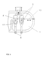
- Fig. 1 einen Querschnitt eines stehenden Kohlevergasers mit separat angeordnetem Zyklonabscheider,
- Fig. 2 einen ausschnittsweisen Querschnitt eines liegenden Kohlevergasers mit integriertem Zyklon;
- Fig. 3 eine Draufsicht zu Fig. 2;
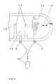
- Fig. 4 einen ausschnittsweisen Querschnitt des Kohlevergasers mit Asche-Staub-Schleusensystem.
- Fig. 1 zeigt schematisch einen Kohlevergasungsreaktor (1) mit einem nachgeschalteten, neben dem Reaktor aufgestellten Heißgaszyklon (2) entsprechend dem Stand der Technik. Der Zykloneintritt ist mit (3) bezeichnet, das Tauchrohr, bestehend aus HT-Blech, mit (4), das feuerfeste Mauerwerk mit (5) und der Druckmantel mit (6).
- Bei dem in den Fig. bis 4 gezeigten Reaktor (1) zur Kohlevergasung handelt es sich um einen Reaktortyp, wie er beispielsweise in der deutschen Patentanmeldung P 36 00 432.4 beschrieben wird, und zwar um einen liegenden Wirbelbett-Reaktor.
- In Fig. 4 ist ganz links ein Teil des Resktorraumes (12) des Reaktors (1) angedeutet, rechts daneben - durch ein Wehr (11) getrennt - der Ascheraum (13) und ganz rechts - wiederum durch ein Wehr (11) getrennt - der Entstaubungsraum (14).
- In dem Entstaubungsraum ist gemäß Fig. 4 nur ein Heißgaszyklon (7) angedeutet, während in den Fig. 2 und 3 der Entstaubungsraum (4) Heißgaszyklone (7) aufweist.
- Die vier Zyklone sind baugleich. Die Gasbeaufschlagung ist infolge des in dem Reaktor herrschenden Überdruckes gleichmäßig. Die Zyklone sind aus HT-Blechen hergestellt. Ein Druckmantel und eine feuerfeste Ausmauerung sind nicht erforderlich.
- Die Reingasaustrittsrohre der Zyklone enthalten an der Rohrdurchführung durch die Reakterwandung Kompensatoren.
- Mit Hilfe von verfahrbaren Verschlußeinrichtungen (10) lassen sich zur Konstanthaltung des Abscheidegrades bei Lastwechseln einzelne Zykloneintritte (3) durch an Gewindespindeln angeordnete Teller schließen. Die Betätigung erfolgt außerhalb des Reaktors über aufgesetzte Elektromotoren. Die Auflage des Tellers auf dem Zykloneintritt bedarf keiner Dichtung, weil kein nennenswerter Differenzdruck vorherrscht. Die Durchführung der Verschlußeinrichtung (10) durch die Reaktorwand erfolgt in wassergekählten Stoffbuchsen mit Sperrgasringen.
- Zum Austrag des von den Heißgaszyklonen (7) abgeschiedenen Staubes sind wassergekühlte Zellenräder (8) angeordnet. Die Asche aus dem Ascheraum (13) wird mit Hilfe des ebenfalls wassergekühlten Zellenrades (9) ausgetragen.
- Durch die Anordnung der Heißgaszyklone innerhalb des Reaktors wird aufgrund der geometrischen Verhältnisse die Möglichkeit geschaffen, entsprechend Fig. 4 Asche unc Staub mit nur einem Schleusensystem (15) auszutragen.
Claims (3)
Applications Claiming Priority (2)
| Application Number | Priority Date | Filing Date | Title |
|---|---|---|---|
| DE19863630916 DE3630916A1 (de) | 1986-09-11 | 1986-09-11 | Reaktor zur kohlevergasung |
| DE3630916 | 1986-09-11 |
Publications (2)
| Publication Number | Publication Date |
|---|---|
| EP0259577A2 true EP0259577A2 (de) | 1988-03-16 |
| EP0259577A3 EP0259577A3 (de) | 1988-09-14 |
Family
ID=6309352
Family Applications (1)
| Application Number | Title | Priority Date | Filing Date |
|---|---|---|---|
| EP87110422A Withdrawn EP0259577A3 (de) | 1986-09-11 | 1987-07-18 | Reaktor zur Kohlevergasung |
Country Status (7)
| Country | Link |
|---|---|
| EP (1) | EP0259577A3 (de) |
| JP (1) | JPS6375093A (de) |
| CN (1) | CN87106252A (de) |
| BR (1) | BR8704701A (de) |
| DE (1) | DE3630916A1 (de) |
| PT (1) | PT85659A (de) |
| ZA (1) | ZA876599B (de) |
Families Citing this family (2)
| Publication number | Priority date | Publication date | Assignee | Title |
|---|---|---|---|---|
| JPH0613240Y2 (ja) * | 1986-10-23 | 1994-04-06 | バブコツク日立株式会社 | 石炭等のガス化装置 |
| CN101285007B (zh) * | 2008-06-06 | 2011-06-22 | 沈阳清井环保机械工程有限公司 | 煤制气高、低温干法卸灰方法 |
Family Cites Families (10)
| Publication number | Priority date | Publication date | Assignee | Title |
|---|---|---|---|---|
| US1890070A (en) * | 1931-07-14 | 1932-12-06 | Prat Daniel Corp | Dust separator control |
| DE974634C (de) * | 1951-03-03 | 1961-03-09 | Ruhrgas Ag | Verfahren zur Brennglaserzeugung durch Vergasen eines feinkoernigen Brennstoffes |
| GB687097A (en) * | 1951-11-09 | 1953-02-04 | Richard Fritz Heinrich | Improvements relating to multi-cyclone assemblies |
| FR1403764A (fr) * | 1964-05-12 | 1965-06-25 | Aerotec Ind | Séparation centrifuge à plusieurs compartiments |
| DE1271655B (de) * | 1964-07-08 | 1968-07-04 | Donald A Sillers Jun | Vorrichtung zum Herabsetzen des Partikelgehaltes von und der Pulsationen in einem Gasstrom |
| US4257788A (en) * | 1979-04-16 | 1981-03-24 | Nicholas Nassir | Power recovery hot gas separator |
| DE2947222C2 (de) * | 1979-11-23 | 1987-05-07 | Carbon Gas Technologie GmbH, 4030 Ratingen | Vorrichtung zur Vergasung von festen, staubförmigen bis stückigen kohlenstoffhaltigen Brennstoffen und deren Verwendung |
| FR2530796A1 (fr) * | 1982-07-21 | 1984-01-27 | Creusot Loire | Dispositif de conversion et de recuperation thermique |
| US4588558A (en) * | 1983-09-06 | 1986-05-13 | Mobil Oil Corporation | Closed FCC cyclone system |
| EP0153624A3 (de) * | 1984-02-28 | 1986-08-13 | Ruhrkohle Aktiengesellschaft | Gaserzeugungsanlage (Wirbelschicht- oder Flugstrom-Druckreaktor mit Zyklonreinigung |
-
1986
- 1986-09-11 DE DE19863630916 patent/DE3630916A1/de not_active Withdrawn
-
1987
- 1987-07-18 EP EP87110422A patent/EP0259577A3/de not_active Withdrawn
- 1987-09-03 JP JP62219320A patent/JPS6375093A/ja active Pending
- 1987-09-03 ZA ZA876599A patent/ZA876599B/xx unknown
- 1987-09-08 PT PT85659A patent/PT85659A/pt not_active Application Discontinuation
- 1987-09-10 BR BR8704701A patent/BR8704701A/pt unknown
- 1987-09-11 CN CN198787106252A patent/CN87106252A/zh active Pending
Also Published As
| Publication number | Publication date |
|---|---|
| PT85659A (pt) | 1988-10-14 |
| CN87106252A (zh) | 1988-05-11 |
| DE3630916A1 (de) | 1988-03-24 |
| JPS6375093A (ja) | 1988-04-05 |
| ZA876599B (en) | 1988-03-14 |
| BR8704701A (pt) | 1988-04-26 |
| EP0259577A3 (de) | 1988-09-14 |
Similar Documents
| Publication | Publication Date | Title |
|---|---|---|
| DE3625992C2 (de) | ||
| EP0616023A1 (de) | Vergasungsapparat für die Druckvergasung von feinteiligen Brennstoffen | |
| DE3409106C2 (de) | ||
| DE2503330B2 (de) | Vorrichtung zum Kalzinieren von Rohmaterial | |
| DE948054C (de) | Verfahren und Vorrichtung zum Abstreifen und nachfolgenden Regenerieren feinverteilter, mit brennbaren Stoffen verunreinigter fester Stoffe | |
| DE3107156A1 (de) | Anlage zur erzeugung von gasfoermigen produkten | |
| DE3225509C2 (de) | Wirbelschichtreaktor | |
| DE19834881B4 (de) | Wirbelschicht-Feuerungssystem mit Dampferzeugung | |
| EP0441999B1 (de) | Einrichtung zur Überwachung des Wasserstands eines Kessels | |
| EP0259577A2 (de) | Reaktor zur Kohlevergasung | |
| EP0253273B1 (de) | Vorrichtung zur Gasentstaubung | |
| DE3208421C2 (de) | ||
| EP0205718B1 (de) | Zyklondampferzeuger | |
| DE2650491C2 (de) | Gas-Dampf-Turbinenanlage zur Erzeugung elektrischer Energie | |
| EP0330666B1 (de) | Wirbelschichtreaktor aus edelstahlgussgehäuse | |
| DE3004847C2 (de) | Dampferzeuger mit einer Wirbelschichtfeuerung | |
| DE3714749A1 (de) | Verfahren und vorrichtung zum ausschleusen von feinkoernigen, heissen feststoffen | |
| EP1133539B1 (de) | Reaktor zum vergasen körniger brennstoffe, die ein festbett bilden | |
| EP0035783B1 (de) | Verfahren und Vorrichtung zur Strom- und Wärmeerzeugung aus Brennstoffen | |
| DE1407941C3 (de) | Schlauchfilteranlage für Nieder- und Hochdruck-Trockengasreinigung | |
| DE3638766C2 (de) | ||
| DE2625275A1 (de) | Anlage zur abscheidung von schadstoffen aus luft | |
| DE3434619A1 (de) | Verfahren und vorrichtung zur mehrstufigen veredlung von organischen schuettguetern | |
| DE3703855A1 (de) | Verbrennungsanlage fuer abfallstoffe | |
| DE2635292A1 (de) | Vorrichtung zum abscheiden von fluessigkeiten und feststoffen aus einem gasfoermigen medium |
Legal Events
| Date | Code | Title | Description |
|---|---|---|---|
| PUAI | Public reference made under article 153(3) epc to a published international application that has entered the european phase |
Free format text: ORIGINAL CODE: 0009012 |
|
| AK | Designated contracting states |
Kind code of ref document: A2 Designated state(s): DE ES GB IT NL SE |
|
| PUAL | Search report despatched |
Free format text: ORIGINAL CODE: 0009013 |
|
| AK | Designated contracting states |
Kind code of ref document: A3 Designated state(s): DE ES GB IT NL SE |
|
| STAA | Information on the status of an ep patent application or granted ep patent |
Free format text: STATUS: THE APPLICATION IS DEEMED TO BE WITHDRAWN |
|
| 18D | Application deemed to be withdrawn |
Effective date: 19890315 |
|
| RIN1 | Information on inventor provided before grant (corrected) |
Inventor name: GEBHARDT, JUERGEN, DIPL.-ING. Inventor name: KNOP, KLAUS, DR.-ING. Inventor name: WOLTERS, GUENTER |