EP0259619B1 - Pompe à huile de lubrification - Google Patents
Pompe à huile de lubrification Download PDFInfo
- Publication number
- EP0259619B1 EP0259619B1 EP87111451A EP87111451A EP0259619B1 EP 0259619 B1 EP0259619 B1 EP 0259619B1 EP 87111451 A EP87111451 A EP 87111451A EP 87111451 A EP87111451 A EP 87111451A EP 0259619 B1 EP0259619 B1 EP 0259619B1
- Authority
- EP
- European Patent Office
- Prior art keywords
- pressure
- lubricating oil
- channel
- outlet
- valve
- Prior art date
- Legal status (The legal status is an assumption and is not a legal conclusion. Google has not performed a legal analysis and makes no representation as to the accuracy of the status listed.)
- Expired - Lifetime
Links
- 238000005461 lubrication Methods 0.000 title description 7
- 239000010687 lubricating oil Substances 0.000 claims description 108
- 239000003921 oil Substances 0.000 claims description 55
- 238000002485 combustion reaction Methods 0.000 claims description 31
- 210000003734 kidney Anatomy 0.000 description 8
- 238000001816 cooling Methods 0.000 description 4
- 238000010438 heat treatment Methods 0.000 description 4
- 210000002105 tongue Anatomy 0.000 description 4
- 230000001105 regulatory effect Effects 0.000 description 3
- 208000034423 Delivery Diseases 0.000 description 2
- 230000001419 dependent effect Effects 0.000 description 2
- 230000003247 decreasing effect Effects 0.000 description 1
- 238000010586 diagram Methods 0.000 description 1
- 230000010354 integration Effects 0.000 description 1
- 238000004519 manufacturing process Methods 0.000 description 1
- 239000010705 motor oil Substances 0.000 description 1
Images


Classifications
-
- F—MECHANICAL ENGINEERING; LIGHTING; HEATING; WEAPONS; BLASTING
- F04—POSITIVE - DISPLACEMENT MACHINES FOR LIQUIDS; PUMPS FOR LIQUIDS OR ELASTIC FLUIDS
- F04C—ROTARY-PISTON, OR OSCILLATING-PISTON, POSITIVE-DISPLACEMENT MACHINES FOR LIQUIDS; ROTARY-PISTON, OR OSCILLATING-PISTON, POSITIVE-DISPLACEMENT PUMPS
- F04C14/00—Control of, monitoring of, or safety arrangements for, machines, pumps or pumping installations
- F04C14/24—Control of, monitoring of, or safety arrangements for, machines, pumps or pumping installations characterised by using valves controlling pressure or flow rate, e.g. discharge valves or unloading valves
-
- F—MECHANICAL ENGINEERING; LIGHTING; HEATING; WEAPONS; BLASTING
- F01—MACHINES OR ENGINES IN GENERAL; ENGINE PLANTS IN GENERAL; STEAM ENGINES
- F01M—LUBRICATING OF MACHINES OR ENGINES IN GENERAL; LUBRICATING INTERNAL COMBUSTION ENGINES; CRANKCASE VENTILATING
- F01M1/00—Pressure lubrication
- F01M1/02—Pressure lubrication using lubricating pumps
-
- F—MECHANICAL ENGINEERING; LIGHTING; HEATING; WEAPONS; BLASTING
- F01—MACHINES OR ENGINES IN GENERAL; ENGINE PLANTS IN GENERAL; STEAM ENGINES
- F01M—LUBRICATING OF MACHINES OR ENGINES IN GENERAL; LUBRICATING INTERNAL COMBUSTION ENGINES; CRANKCASE VENTILATING
- F01M1/00—Pressure lubrication
- F01M1/16—Controlling lubricant pressure or quantity
-
- F—MECHANICAL ENGINEERING; LIGHTING; HEATING; WEAPONS; BLASTING
- F04—POSITIVE - DISPLACEMENT MACHINES FOR LIQUIDS; PUMPS FOR LIQUIDS OR ELASTIC FLUIDS
- F04B—POSITIVE-DISPLACEMENT MACHINES FOR LIQUIDS; PUMPS
- F04B49/00—Control, e.g. of pump delivery, or pump pressure of, or safety measures for, machines, pumps, or pumping installations, not otherwise provided for, or of interest apart from, groups F04B1/00 - F04B47/00
- F04B49/22—Control, e.g. of pump delivery, or pump pressure of, or safety measures for, machines, pumps, or pumping installations, not otherwise provided for, or of interest apart from, groups F04B1/00 - F04B47/00 by means of valves
Definitions
- the invention relates to an internal combustion engine according to the preamble of claims 1 and 2.
- Such an internal combustion engine is used in particular for use in motor vehicles.
- This internal combustion engine is the subject of WO-A 86/06797.
- Such internal combustion engines are distinguished on the one hand by the fact that they are operated with very different and constantly changing operating parameters, starting from idling up to maximum load operation at the highest speeds.
- the lubricating oil system must therefore meet the maximum load conditions, but, on the other hand, should not consume unnecessarily much energy in the lower load ranges.
- the known internal combustion engine has a lubricating oil system which, on the one hand, supplies a sufficient quantity of lubricating oil in all operating states, and on the other hand avoids unnecessary, lossy delivery.
- a cell pump is used. That means:
- the cell pump has so many revolving and mutually closed cells that there are always several - at least three - cells with a decreasing volume in the outlet zone. There are a number of outlets corresponding to the number of cells. Some or all of these outlets open into the lubricating oil channel. However, those outlets that are assigned to a cell with a large volume are blocked by a check valve. Only the smallest or the smallest outlet openings assigned to the lubricating oil channel can open directly into the lubricating oil channel without a check valve. A restriction is arranged in the inlet of the pump.
- An internal gear pump is particularly suitable as such a pump.
- the throttle of the inlet is bypassed by a bypass duct, a pressure-controlled throttle valve being located in the bypass duct, which is controlled by the outlet pressure of the lubricating oil pump and which opens the bypass when the pressure in the outlet duct drops.
- the throttle is set in such a way that the amount of lubricating oil that is conveyed by the lubricating oil pump only depends on the speed up to a certain speed.
- This threshold speed can be specified by dimensioning the throttle.
- the lubricating oil system can be used by anyone, e.g. Adjust increased additional demand due to wear by determining the pressure drop and using it to open a bypass. By opening the bypass, the entire delivery capacity or an additional portion of the delivery capacity of the lubricating oil pump can be accessed.
- the object of the invention is to design the internal combustion engine, which is the subject of WO-A 86/06797, in such a way that not only is sufficient lubrication ensured, especially in the cold state, but also that the lubricating oil and the internal combustion engine are rapidly heated to their operating temperature he follows.
- the solution according to claim 1 provides that the quantity of lubricating oil delivered at maximum pressure (minimum throughput) is not limited to the lowest quantity required for sufficient lubrication, but rather in terms of quantity is in a range that at least approximately meets the requirements in normal operation.
- the very compact embodiment of the invention according to claim 2, which is therefore suitable for integration into the lubricating oil pump, provides that the intake oil flow is guided via two throttles which are parallel to one another and which are controlled by one and the same pressure-controlled throttle valve.
- the overlap of the lines in the pressure-controlled throttle valve is such that at maximum pressure the one line string, which is throttled variably by the throttle valve, is closed, while the second line string, which is provided with a fixed throttle or orifice, is completely open.
- the throttling is designed in such a way that the fixed throttle has a passage cross-section in this wiring harness, which ensures the minimum throughput at a pressure difference of 1 bar.
- the overlap is designed so that at operating pressure the second line is closed with the fixed throttle, so that lubricating oil is only drawn in via the pressure-controlled, variable throttle point of the pressure control valve.
- the pressure-controlled throttle valve is designed in such a way that the entire lubricating oil requirement can be covered by this second wiring harness when the second wiring harness is opened as far as possible.
- a lubricating oil system the delivery of which is adapted to the lubricating oil requirement without loss via the pressure control and which, as a special requirement, also ensures an oil delivery which leads to the rapid heating of the cold engine.
- the invention is based on the fact that when the engine is cold and the lubricating oil is cold, the lubricating oil requirement of the engine is very low. This creates in Lube oil system a high oil pressure, which according to the known teachings, cf. DE-A 3 506 629 should lead to the fact that the oil production by the lubricating oil pump would be greatly reduced and adapted to the low lubricating oil requirement. According to the invention, an amount of oil which is greater than the demand is conveyed at high oil pressure.
- the throttling in the inlet can be brought about by a throttle or an orifice.
- a throttle or an orifice For the difference between throttle and orifice, reference is made to Cheek, "Fundamentals of Oil Hydraulics", 4th edition, 1979, pages 47 ff.
- the throttle or orifice in the inlet of the lubricating oil pump is designed or controllable in such a way that, at the highest lubricating oil pressure in the pump outlet, a throughput is achieved which is at least 30% of the normal oil consumption, and that the minimum throughput at the maximum pressure of the lubricating oil system and an oil temperature which is lower than the operating oil temperature (approx. 90 ° C.) is a multiple of the minimum consumption of the engine at the same oil temperature, preferably at least twice, at most 20 times.
- the normal oil consumption here is the oil consumption of the internal combustion engine that occurs at the operating temperature of the engine or lubricating oil.
- This normal oil consumption of the internal combustion engine corresponds to the normal delivery of the lubricating oil pump.
- the normal delivery is regulated by the pressure-controlled throttle valve when the oil and engine are at their operating temperature and the lubricating oil pump is driven at a speed at which it delivers regardless of the speed.
- the minimum consumption is defined here as the oil consumption of the engine, which occurs when the lubricating oil and the engine are cold (20 ° C) and in the lubricating oil system there is the highest permitted pressure at which excess oil quantities are drained into the oil sump via the pressure relief valve.
- the minimum throughput according to this invention is of course dependent on the size of the motor and should be between 8 and 20 l / min.
- the minimum throughput also depends on the desired heating time.
- the minimum throughput is preferably between 70 and 100% of normal oil consumption.
- the minimum throughput depends not only on the opening cross-section and the other design of the throttle or orifice, but also on the properties, in particular the viscosity of the oil and thus also on the temperature of the oil.
- the pressure-controlled valve which can be loaded with two different back pressures, can be switched to different back pressure by an electromagnetic valve.
- the electromagnetic valve detects predetermined operating states, e.g. the lubricating oil temperature, the temperature of certain machine parts, etc.
- the pressure-controlled valve can be loaded in particular with the tank pressure or outside pressure.
- the pressure of the lubricating oil system and, on the other hand, a spring and the tank pressure or atmospheric pressure act on the control piston of the pressure-controlled valve.
- the pressure-controlled valve can be connected to the pressure in the intake duct, a negative pressure. This means that the lubricating oil pressure outweighs the spring force including back pressure and opens the pressure-controlled valve until a correspondingly higher lubricating oil pressure has set in.
- the additional consumer can e.g. are supplied via a pressure relief valve that opens at the higher pressure now set.
- the peculiarity of this invention is that the lessons to be learned from DE-A 3 444 859 and 3 506 629 are adapted to a lubricating oil system.
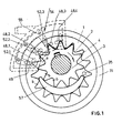
- the outer wheel 1 is freely rotatably mounted in the housing 31.
- the outer wheel 1 has an internal toothing 2.
- the cylindrical housing 31 is closed on both sides by the covers 32 and 33.
- the shaft 34 is rotatably mounted in the cover 32 and driven by the internal combustion engine.
- the inner wheel 3 is rotatably mounted on the shaft 34.
- the inner wheel 3 has an external toothing 4 which engages with the internal toothing 2 of the outer wheel 1.
- the interior of the pump which lies outside the engagement area, is filled with sickle 57.
- the sickle hugs the circles of the gears to a large extent.
- the inlet channel 35 is located in the cover 33.
- the pump forms - as shown in FIG. 1 - on the outlet side between the intermeshing teeth of the outer wheel 1 and the inner wheel 3 four cells which are closed in the circumferential direction and the axial direction and which have been completely or partly filled with 01 via the inlet channel 35.
- Four outlet kidneys 48.1, 48.2, 48.3, 48.4 are introduced into the cover 32. 2 to 4, only one of these outlet kidneys can be seen. This outlet kidney is designated there by 48.
- Each of the outlet kidneys is connected to an outlet channel 49 drilled in the cover 33.
- the outlet channel is also directed radially outwards, as shown in FIGS. 2 to 4. Therefore, each outer channel 49 opens on the outside of the cover 33 as close as possible to the housing 31.
- An outlet housing 50 is placed on the cover 33 in a pressure-tight manner.
- the outlet housing 50 forms an outlet chamber which is connected to the outlet kidneys 48.1 to 48.4 via a pressure channel 49 and a bore 52.
- the bores 52.1, 52.2 and 52.3 are each closed by a check valve.
- the check valve is formed by an m-shaped plate which is screwed against the wall 53 of the outlet housing 50.
- the tongues protruding from the common crossbeam 55 of the check valve 54 cover the bores 52. Therefore, these tongues act as check valves.
- Each check valve only releases the connection from the respective pressure cell formed between the teeth via the respective outlet kidney 48, pressure channel 49 and bore 52 if the pressure of the outlet cell is at least equal to the outlet pressure in the outlet chamber 51.
- the last and smallest pressure cell can be connected directly to the outlet chamber via kidney 48.4 and corresponding channels 49, 52.
- the outlet chamber 51 has an outlet which leads into the common lubricating oil channel 29.
- This operating state is maintained at low speeds of the motor vehicle engine.
- the lubricating oil flow is therefore proportional to the demand according to the speed.
- the lubricating oil pump automatically adapts to an increased demand.
- the lubricating oil pump therefore meets the increasing need for lubricating oil throughout the life of the motor vehicle engine.
- the lubricating oil pump works economically even with a new engine with a relatively low need for lubricating oil, since this lubricating oil pump avoids that an unnecessary delivery portion must be returned to the sump with losses.
- the inlet 35 communicates with the sump 36 via a pressure-controlled throttle valve 39.
- the inlet 35 of the lubricating oil pump is connected to the oil sump of the engine (tank 36) by means of the parallel connection through two channels, namely bypass channel 38 and suction channel 67.
- the constant throttle 37 is located in the intake duct 67.
- the bypass duct 38 also has a throttle resistance, which is symbolically designated here with throttle 63.
- the pressure-controlled throttle valve 39 has a piston 40 which is movable in a housing against the force of a spring 42.
- the piston 40 has two piston collars 68 and 69, which are arranged at a distance from one another on a piston rod.
- the piston collar 69 delimits the pressure-free spring chamber 27 of the spring 42.
- the other piston collar 68 in the control chamber 43 is acted upon by the outlet pressure of the lubricating oil pump via the control line 44.
- valve housing has the inlet 45, which is connected to the bypass channel, and the outlet 46, which is connected to the tank 36.
- Inlet 45 and outlet 46 are one arranged opposite one another that they are opened simultaneously by the control edge of the end faces when the control collar 68 is displaced under the force of the spring 42 against the outlet pressure of the lubricating oil pump.
- the axial extent of the outlet 46 is greater than the axial extent of the inlet 45. This will be discussed later.
- the intake duct 67 is connected to the tank via the throttle valve 39 through inlet 71 and outlet 72.
- Inlet 71 and outlet 72 are on the same normal plane. They are opened and closed by the end face or control edge 70 of the piston collar 69 facing away from the spring.
- the function of the throttle valve 39 as a function of the outlet pressure is described below for the embodiment according to FIG. 2, in particular with reference to FIGS. 3A and 3B.
- the piston collar 68 with its control edge 41 releases the flow of the bypass channel 38 from the inlet 45 to the outlet 46.
- Lubricating oil can now be sucked in from the sump 36 without throttling through the throttle valve via bypass duct 38 from the pump.
- the intake duct 67 with inlet 71 and outlet 72 is completely blocked by the control collar 69, as can be seen in FIG. 3A.
- This position of the throttle valve ensures the greatest normal throughput or covers the greatest normal consumption of the engine.
- Fig. 3A This is the control range of the throttle valve, in which, by regulating the outlet pressure, the delivery of the pump to the changing consumption during normal operation of the engine, i.e. at the permissible operating temperature of the oil.
- control collar 69 with its control edge 70 increasingly opens inlet 71 and outlet 72 of intake duct 67.
- inlet 45 and outlet 46 of bypass duct 38 are completely closed ( Fig. 2). In this position, inlet 71 and outlet 72 of the intake duct 67 are completely open.
- the outlet 46 is made axially longer in the direction of the control chamber 43 than the inlet 45. Therefore, inlet 45 remains closed by the control collar 68, while outlet 46 together with the control edge 47 acts as an outlet throttle.
- the outlet pressure of the lubricating oil pump in outlet chamber 51 is regulated to a constant maximum value via this outlet throttle. This maximum value depends on the size of the spring force. This state is shown in Fig. 3B.
- the lubricating oil that escapes from the outlet chamber 51 via the control line 44, the control chamber 43, the outlet 46 into the oil sump 36 is throttled down at the throttle point between the control edge 47 and outlet 46 from the maximum pressure of the outlet chamber 51 to the pressure in the oil sump 36. This throttling occurs due to energy loss, which is largely converted into heat, namely heating the oil.
- the passage 71, 72 for the intake duct 67 is opened. Therefore, the partial flows carried in parallel add up in such a way that the sum of the oil flow in the inlet 35 is at least equal to 30% of the maximum possible amount of oil, provided the oil is of the same quality.
- the passages 71, 72 for the intake duct 67 are opened completely, so that the greatest possible oil flow Q37 flows there, which is approximately as large as the oil flow flowing in normal operation.
- the lubricating oil pump also meets other requirements of special operating conditions. For example, occur that the lubricating oil heats up excessively or that engine parts have to be cooled by lubricating oil due to special performance requirements.
- the pressure channel 56 branches into two systems on the outlet side of the lubricating oil pump.
- lubricating oil is supplied to a multiplicity of bearings and lubrication points 73 via a multiplicity of lines 29.
- a drain leads from each lubrication point into the sump.
- the lubricating oil line 29 is secured by the pressure-controlled throttle valve 39, which acts as a pressure relief valve.
- the setting of the spring 42 ensures that the pressure does not exceed a harmful limit.
- a maximum pressure of 6 bar can be set.
- a second oil channel 74 leads via a pressure relief valve 75 to a special consumer 76, for which lubricating oil is only required in special situations.
- This special consumer 76 can e.g. is a piston cooling nozzle that is only operated when piston cooling is required or when sufficient lubricating oil is available.
- the pressure relief valve 75 is set so that it opens at a lower pressure than the control edge 47 opposite the outlet 46 in the throttle valve 39. Therefore, the special consumer 76 is only supplied with lubricating oil if a sufficiently high supply of lubricating oil is available for the lubricating oil line 29.
- a switching valve 77 can be switched into the pressure channel 74, which is switched electromagnetically.
- This valve is actuated via signal line 60 and amplifier 61 by a temperature sensor 62.
- the temperature sensor can e.g. - as indicated - the oil temperature or the temperature of a machine part, e.g. Pistons to be detected. It is also possible to use a different measuring instrument, e.g. Speed counter to use.
- the message line can also be used to record other extraordinary operating conditions. In any event, the valve 77 serves the purpose of meeting an extraordinary need.
- the specified setting of the pressure relief valve 75 and the throttle valve 39 ensures, however, that in any case the lubricating oil supply to the lubrication points 73 is initially ensured without leaving the control range of the throttle valve 39.
- the inlet 35 of the pump is connected to the sump 36 via a throttle 37.
- a bypass 38 which is connected in parallel to the throttle duct 37, there is a pressure-controlled throttle valve 39.
- the piston 40 of the valve controls with its control edge 41 the openings 45, 46 of the bypass duct 38 to the sump 36.
- the piston is on one side loaded with a spring 42.
- the piston in control chamber 43 is acted upon by the outlet pressure via control line 44.
- the constant throttle 37 in the intake duct is now designed so that the throughput according to the invention is achieved even when the bypass duct 38 is closed by the throttle valve 39.
- the constant choke has a sufficiently large cross section.
- an additional pressure control of the pressure-controlled throttle valve 39 is provided.
- This pressure control is used by the solenoid valve 59.
- the solenoid valve 59 is used via the signal line 60, amplifier 61 and a measuring instrument, e.g. Temperature sensor 62, an operating state of the lubricating oil circuit, e.g. the temperature.
- the solenoid valve 59 has two switching states.
- the valve 59 connects the spring chamber 27 of the pressure control valve 39 to the intake duct 35, it being emphasized that there is a negative pressure here as a result of the throttling between the tank 36 and the intake duct 35.
- the solenoid valve 59 connects the spring chamber 27 to the tank 36 via channel 28 the front control edge 47 in the control chamber 43 prevailing lubricating oil system pressure and shift the control piston 40 - in FIG. 4 - to the left.
- the throttling at control edge 41 is partially eliminated, so that a larger oil flow is available in the intake duct 35 and the higher lubricating oil requirement of the system can be covered.
- a pressure relief valve 30 is now additionally provided in the connecting line 29 to an additional consumer to be connected. This pressure relief valve 30 is set so that it opens at the higher system pressure, so that the additional consumers are supplied with the additional oil supplied can. This system is particularly applicable for lubricating oil cooling of engine parts.
Landscapes
- Engineering & Computer Science (AREA)
- Mechanical Engineering (AREA)
- General Engineering & Computer Science (AREA)
- Physics & Mathematics (AREA)
- Fluid Mechanics (AREA)
- Lubrication Of Internal Combustion Engines (AREA)
Claims (9)
Priority Applications (1)
| Application Number | Priority Date | Filing Date | Title |
|---|---|---|---|
| US07/118,660 US4850814A (en) | 1987-01-09 | 1987-11-09 | Hydraulic gear pump |
Applications Claiming Priority (2)
| Application Number | Priority Date | Filing Date | Title |
|---|---|---|---|
| DE3627414 | 1986-08-13 | ||
| DE19863627414 DE3627414A1 (de) | 1986-08-13 | 1986-08-13 | Verbrennungsmotor |
Publications (2)
| Publication Number | Publication Date |
|---|---|
| EP0259619A1 EP0259619A1 (fr) | 1988-03-16 |
| EP0259619B1 true EP0259619B1 (fr) | 1990-10-17 |
Family
ID=6307281
Family Applications (1)
| Application Number | Title | Priority Date | Filing Date |
|---|---|---|---|
| EP87111451A Expired - Lifetime EP0259619B1 (fr) | 1986-08-13 | 1987-08-07 | Pompe à huile de lubrification |
Country Status (2)
| Country | Link |
|---|---|
| EP (1) | EP0259619B1 (fr) |
| DE (2) | DE3627414A1 (fr) |
Cited By (1)
| Publication number | Priority date | Publication date | Assignee | Title |
|---|---|---|---|---|
| DE102009020405B4 (de) | 2008-05-21 | 2018-08-23 | GM Global Technology Operations LLC (n. d. Ges. d. Staates Delaware) | Dynamisches Motorölansaugsystem, dynamische Motorölansaugrohranordnung und Verbrennungsmotor |
Families Citing this family (5)
| Publication number | Priority date | Publication date | Assignee | Title |
|---|---|---|---|---|
| DE3933978A1 (de) * | 1989-10-11 | 1991-05-02 | Eisenmann Siegfried A | Sauggeregelte zahnringpumpe |
| DE4129854A1 (de) * | 1991-09-07 | 1993-03-11 | Teves Gmbh Alfred | Zahnradpumpe mit einer nichtlinear von der drehzahl abhaengenden foerdermenge |
| DE4241002C2 (de) * | 1991-12-19 | 2001-05-10 | Luk Automobiltech Gmbh & Co Kg | Hydraulische Rotationszellenpumpe |
| DE4209143C1 (fr) * | 1992-03-20 | 1993-04-15 | Siegfried A. Dipl.-Ing. 7960 Aulendorf De Eisenmann | |
| DE19631910B4 (de) * | 1996-07-31 | 2005-02-03 | Andreas Voulgaris | Hydraulische Maschine der Zahnring-Bauart |
Family Cites Families (7)
| Publication number | Priority date | Publication date | Assignee | Title |
|---|---|---|---|---|
| US1537013A (en) * | 1921-02-02 | 1925-05-05 | Howard C Marmon | Oiling system |
| US2550967A (en) * | 1945-06-04 | 1951-05-01 | Caterpillar Tractor Co | Motor lubrication |
| GB836321A (en) * | 1957-07-02 | 1960-06-01 | Daimler Benz Ag | New or improved automatic control means for a forced lubricating oil system of a fuel injection pump for an internal combustion engine |
| CH385632A (de) * | 1960-10-19 | 1964-12-15 | Schweizerische Lokomotiv | Axialkolbenpumpe mit Steuereinrichtung zum Verändern der Fördermenge |
| DE2920685A1 (de) * | 1979-05-22 | 1980-12-04 | Bosch Gmbh Robert | Drucklufterzeugungsanlage |
| DE3210759A1 (de) * | 1981-09-17 | 1983-10-06 | Walter Schopf | Pumpenkombination mit mengenreguliereinrichtung |
| DE3506629A1 (de) * | 1984-03-01 | 1985-10-03 | Barmag Barmer Maschinenfabrik Ag, 5630 Remscheid | Hydrauliksysteme |
-
1986
- 1986-08-13 DE DE19863627414 patent/DE3627414A1/de not_active Withdrawn
-
1987
- 1987-08-07 EP EP87111451A patent/EP0259619B1/fr not_active Expired - Lifetime
- 1987-08-07 DE DE8787111451T patent/DE3765607D1/de not_active Expired - Lifetime
Cited By (1)
| Publication number | Priority date | Publication date | Assignee | Title |
|---|---|---|---|---|
| DE102009020405B4 (de) | 2008-05-21 | 2018-08-23 | GM Global Technology Operations LLC (n. d. Ges. d. Staates Delaware) | Dynamisches Motorölansaugsystem, dynamische Motorölansaugrohranordnung und Verbrennungsmotor |
Also Published As
| Publication number | Publication date |
|---|---|
| DE3765607D1 (de) | 1990-11-22 |
| DE3627414A1 (de) | 1988-02-18 |
| EP0259619A1 (fr) | 1988-03-16 |
Similar Documents
| Publication | Publication Date | Title |
|---|---|---|
| DE69113195T2 (de) | Fluidpumpe für Doppelfördermenge. | |
| EP0724068B1 (fr) | Système d'amenée d'huile | |
| DE3333647C2 (de) | Schmiermittelpumpe für die Druckerzeugung bei einem druckumlaufgeschmierten Verbrennungsmotor | |
| EP3516273B1 (fr) | Traitement de fluide hydraulique à alimentation en huile par système de pompe double | |
| DE10028416A1 (de) | Steuerung für eine variable Pumpe für einen Hydraulikventilatorantrieb | |
| DE112008000377B4 (de) | Hydraulisches System | |
| DE3824398C2 (de) | Schmierölpumpe | |
| DE102020125021A1 (de) | Reihenkolbenpumpe | |
| EP1903238B1 (fr) | Système hydraulique | |
| DE4224973C2 (de) | Fluidversorgungssystem mit Druckbegrenzung | |
| EP1463888B1 (fr) | Dispositif pour reguler la pression de pompes hydrauliques | |
| EP0225338B1 (fr) | Pompe a capacite variable | |
| WO1993024346A1 (fr) | Pompe hydraulique entrainee par un moteur a combustion interne | |
| DE60305812T2 (de) | Hydraulische Pumpe mit doppeltem Auslass und System mit derselben | |
| DE3906477C2 (fr) | ||
| EP0259619A1 (fr) | Pompe à huile de lubrification | |
| EP0561304B1 (fr) | Pompe à engrenages avec contrôle de l'aspiration | |
| DE102018219122A1 (de) | Kühlungs-Priorisierungsventil für ein Hydrauliksystem eines Kraftfahrzeug-Getriebes | |
| DE102017118525A1 (de) | Hydraulisches steuersystem für ein getriebe | |
| EP0499794B1 (fr) | Pompe hydraulique | |
| DE102009060188A1 (de) | Verstellventil für die Verstellung des Fördervolumens einer Verdrängerpumpe mit Kaltstartfunktion | |
| WO2008031390A1 (fr) | système hydraulique d'amenée d'un fluide hydraulique à un consommateur | |
| EP0208692B1 (fr) | Pompe a piston | |
| AT526441B1 (de) | Ölversorgungsvorrichtung | |
| DE69014555T2 (de) | Fluidpumpe für Doppelfördermenge. |
Legal Events
| Date | Code | Title | Description |
|---|---|---|---|
| PUAI | Public reference made under article 153(3) epc to a published international application that has entered the european phase |
Free format text: ORIGINAL CODE: 0009012 |
|
| AK | Designated contracting states |
Kind code of ref document: A1 Designated state(s): DE FR GB IT |
|
| 17P | Request for examination filed |
Effective date: 19880213 |
|
| 17Q | First examination report despatched |
Effective date: 19890213 |
|
| ITF | It: translation for a ep patent filed | ||
| GRAA | (expected) grant |
Free format text: ORIGINAL CODE: 0009210 |
|
| AK | Designated contracting states |
Kind code of ref document: B1 Designated state(s): DE FR GB IT |
|
| ET | Fr: translation filed | ||
| GBT | Gb: translation of ep patent filed (gb section 77(6)(a)/1977) | ||
| REF | Corresponds to: |
Ref document number: 3765607 Country of ref document: DE Date of ref document: 19901122 |
|
| PLBE | No opposition filed within time limit |
Free format text: ORIGINAL CODE: 0009261 |
|
| STAA | Information on the status of an ep patent application or granted ep patent |
Free format text: STATUS: NO OPPOSITION FILED WITHIN TIME LIMIT |
|
| ITTA | It: last paid annual fee | ||
| 26N | No opposition filed | ||
| PGFP | Annual fee paid to national office [announced via postgrant information from national office to epo] |
Ref country code: FR Payment date: 20000807 Year of fee payment: 14 |
|
| PGFP | Annual fee paid to national office [announced via postgrant information from national office to epo] |
Ref country code: GB Payment date: 20000811 Year of fee payment: 14 |
|
| PG25 | Lapsed in a contracting state [announced via postgrant information from national office to epo] |
Ref country code: GB Free format text: LAPSE BECAUSE OF NON-PAYMENT OF DUE FEES Effective date: 20010807 |
|
| GBPC | Gb: european patent ceased through non-payment of renewal fee |
Effective date: 20010807 |
|
| PG25 | Lapsed in a contracting state [announced via postgrant information from national office to epo] |
Ref country code: FR Free format text: LAPSE BECAUSE OF NON-PAYMENT OF DUE FEES Effective date: 20020430 |
|
| REG | Reference to a national code |
Ref country code: FR Ref legal event code: ST |
|
| PGFP | Annual fee paid to national office [announced via postgrant information from national office to epo] |
Ref country code: DE Payment date: 20030901 Year of fee payment: 17 |
|
| PG25 | Lapsed in a contracting state [announced via postgrant information from national office to epo] |
Ref country code: DE Free format text: LAPSE BECAUSE OF NON-PAYMENT OF DUE FEES Effective date: 20050301 |
|
| PG25 | Lapsed in a contracting state [announced via postgrant information from national office to epo] |
Ref country code: IT Free format text: LAPSE BECAUSE OF NON-PAYMENT OF DUE FEES;WARNING: LAPSES OF ITALIAN PATENTS WITH EFFECTIVE DATE BEFORE 2007 MAY HAVE OCCURRED AT ANY TIME BEFORE 2007. THE CORRECT EFFECTIVE DATE MAY BE DIFFERENT FROM THE ONE RECORDED. Effective date: 20050807 |