EP0259719A2 - Pont déplaçable - Google Patents
Pont déplaçable Download PDFInfo
- Publication number
- EP0259719A2 EP0259719A2 EP87112529A EP87112529A EP0259719A2 EP 0259719 A2 EP0259719 A2 EP 0259719A2 EP 87112529 A EP87112529 A EP 87112529A EP 87112529 A EP87112529 A EP 87112529A EP 0259719 A2 EP0259719 A2 EP 0259719A2
- Authority
- EP
- European Patent Office
- Prior art keywords
- ramp
- bridge
- bridge according
- connecting part
- recess
- Prior art date
- Legal status (The legal status is an assumption and is not a legal conclusion. Google has not performed a legal analysis and makes no representation as to the accuracy of the status listed.)
- Granted
Links
- 230000008878 coupling Effects 0.000 description 2
- 238000010168 coupling process Methods 0.000 description 2
- 238000005859 coupling reaction Methods 0.000 description 2
- 238000005452 bending Methods 0.000 description 1
- 230000037431 insertion Effects 0.000 description 1
- 238000003780 insertion Methods 0.000 description 1
Images


Classifications
-
- E—FIXED CONSTRUCTIONS
- E01—CONSTRUCTION OF ROADS, RAILWAYS, OR BRIDGES
- E01D—CONSTRUCTION OF BRIDGES, ELEVATED ROADWAYS OR VIADUCTS; ASSEMBLY OF BRIDGES
- E01D15/00—Movable or portable bridges; Floating bridges
- E01D15/14—Floating bridges, e.g. pontoon bridges
-
- E—FIXED CONSTRUCTIONS
- E01—CONSTRUCTION OF ROADS, RAILWAYS, OR BRIDGES
- E01D—CONSTRUCTION OF BRIDGES, ELEVATED ROADWAYS OR VIADUCTS; ASSEMBLY OF BRIDGES
- E01D15/00—Movable or portable bridges; Floating bridges
- E01D15/12—Portable or sectional bridges
- E01D15/133—Portable or sectional bridges built-up from readily separable standardised sections or elements, e.g. Bailey bridges
Definitions
- the invention relates to a relocatable bridge which has at its two ends at least one non-height-adjustable ramp end tapering in a vertical longitudinal section.
- Mobile bridges which are mostly used as pioneering bridges, generally have ramps at their ends, which can be adjusted in height by appropriate linkages. Such a height adjustment is usually necessary if these bridges are used as floating bridges on pontoons.
- Fixed bridges that is, bridges that are not used as floating bridges, on the other hand, generally do not require a height adjustment of their ends, which are also ramp-shaped. This is especially true for shorter fixed bridges.
- bridges have the disadvantage of not being suitable as pioneer bridges for all applications.
- these cases of application also - if the bridge parts are buoyant - can also be used as a ferry. In this case, the end of the bridge, namely the ramp, must be raised to serve as a vehicle bow so that the ferry thus formed is not flooded.
- the invention is based, to lay bridges of the type mentioned for all the aforementioned applications, i.e. to make it universally applicable.
- the invention has the further advantage that this fixed bridge can not only be used as a floating bridge and ferry, but can also be extended when used as a fixed bridge.
- the ramp end 1 of a relocatable bridge rests on a pontoon 3 floating in a river 2.
- the tip 4 of the ramp end 1 is connected to a connecting part 5, which has a swivel joint 6 on the upper side, the axis of which runs transversely to the longitudinal direction of the bridge, and to which a support 7 is articulated, which has its other end on the bank 8 of the river 2 lies on.
- the carrier 7 has on its underside longitudinal ribs 9 which form two projecting double eyes 10, one end of a hydraulic cylinder 11 being articulated to each double eye, the other end of which is articulated with a double eye 13 located opposite on a lower projection 12 of the connecting part 5 is.
- the two hydraulic cylinders 11 are connected via lines 14 to a pump unit 15 arranged in the interior of a pontoon 3 for actuating the hydraulic cylinders.
- the two outer pivot positions of the carrier 7 caused thereby are also indicated in FIG. 1.
- a SpeI arranged between two ribs 9 in the carrier 7 and connected to the hydraulic cylinders 11
- the device 16 serves to provide resilient support for the swivel joint 6 when under load.
- the storage device also brings about an automatic return of the cylinders 11 to the starting position after the bridge is relieved.
- This ramp 7 and the ramp end 1 each form only one track of the relocatable bridge.
- the second track not shown in FIG. 2, is accordingly beyond the longitudinal axis 17 of the bridge. If necessary, instead of the two ramps, only a single, correspondingly wider ramp can be provided or the two ramps e.g. to be connected by striving.
- the connecting part is formed by two angle pieces 18, which have the width shown in FIG. 4 and are connected to one another via an upper carriageway plate 19.
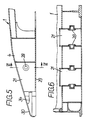
- the angle pieces 18 each form a projection 20 which engages in a corresponding recess 21 of the tip of the ramp end 1 shown on a larger scale in FIGS. 5 and 6.
- the other end of the angle piece 18 has two eyes belonging to the swivel joint 6 on its upper side, while the eyes 13 for projecting one of the cylinders 11 are arranged underneath and projecting downwards.
- a release device 21 is mounted in the projection 20, by means of which a pin 22 can be moved up and down to move two bolts 23 laterally in the direction of their common axis.
- a vertical apron provided with oblique grooves 24 is displaced downward, as a result of which in the oblique grooves 24 are displaceable, in each case one of the bolts 23 arranged guide pins 26 are pushed outwards.
- Guide pins, not shown, opposite the guide pins 26 engage in horizontally running grooves 27 in order to prevent the bolts 23 from rotating.
- the bolts 23 When disengaging, the bolts 23 engage in bores 28 which can be seen in FIGS. 5 and 6 and which, in the coupling position of the connecting part 5, lie opposite the bolts 23. In this position, the underside of the projection 20 rests on a plate 29 which closes off the part of the recess 21 in question facing the bridge at the bottom.
- the comb-like protruding tips 30, which are formed by the recesses 21 in the ramp end 1, lie laterally in the coupling position on pressure pieces 31, which are laterally projecting on the angle pieces 18. The pressure pieces 31 are only acted upon when the bridge is loaded. Shoulders 33 are supported on the top of the tip 30 and, like the track 19, connect the angle pieces 18 to one another.
- each angle piece has two coaxially opposite guide pins 33 on the side, which engage in opposite grooves 34 of the tip 30 when threading.
- the bending moment occurring when the bridge is loaded in the area of the connection piece 5 is absorbed by a pair of forces in which the pressure force is transmitted via the pressure piece 31 and the tensile force is transmitted via the bolts 23.
Landscapes
- Engineering & Computer Science (AREA)
- Architecture (AREA)
- Civil Engineering (AREA)
- Structural Engineering (AREA)
- Bridges Or Land Bridges (AREA)
Applications Claiming Priority (2)
| Application Number | Priority Date | Filing Date | Title |
|---|---|---|---|
| DE19863629842 DE3629842A1 (de) | 1986-09-02 | 1986-09-02 | Verlegbare bruecke |
| DE3629842 | 1986-09-02 |
Publications (3)
| Publication Number | Publication Date |
|---|---|
| EP0259719A2 true EP0259719A2 (fr) | 1988-03-16 |
| EP0259719A3 EP0259719A3 (en) | 1989-01-25 |
| EP0259719B1 EP0259719B1 (fr) | 1991-03-27 |
Family
ID=6308747
Family Applications (1)
| Application Number | Title | Priority Date | Filing Date |
|---|---|---|---|
| EP87112529A Expired - Lifetime EP0259719B1 (fr) | 1986-09-02 | 1987-08-28 | Pont déplaçable |
Country Status (4)
| Country | Link |
|---|---|
| EP (1) | EP0259719B1 (fr) |
| DE (2) | DE3629842A1 (fr) |
| ES (1) | ES2021312B3 (fr) |
| NO (1) | NO873509L (fr) |
Cited By (3)
| Publication number | Priority date | Publication date | Assignee | Title |
|---|---|---|---|---|
| WO1998032649A1 (fr) * | 1997-01-24 | 1998-07-30 | Mannesmann Rexroth Ag | Dispositif pour le reglage de rampes |
| US7017219B2 (en) * | 2003-02-25 | 2006-03-28 | Eurobridge Mobile Bruecken Gmbh | Dismountable bridge |
| KR101274607B1 (ko) * | 2011-06-10 | 2013-06-14 | 주식회사 위더스씨아이에스 | 수상부유 구조물의 도교 연결 시스템 |
Families Citing this family (2)
| Publication number | Priority date | Publication date | Assignee | Title |
|---|---|---|---|---|
| US5816767A (en) * | 1996-07-08 | 1998-10-06 | Mann; Fred W. | Transport locking system for movable-deck vehicle |
| US8118315B2 (en) | 2008-06-26 | 2012-02-21 | Mann Fred W | Trailer with hydraulic bed tilt control |
Family Cites Families (10)
| Publication number | Priority date | Publication date | Assignee | Title |
|---|---|---|---|---|
| DE1100067B (de) * | 1958-05-24 | 1961-02-23 | Beteiligungs & Patentverw Gmbh | Zerlegbare Bruecke, z. B. Schwimmbruecke oder Grabenbruecke |
| DE1184928B (de) * | 1959-06-05 | 1965-01-07 | Beteiligungs & Patentverw Gmbh | Einrichtung zum Herstellen einer loesbaren, in drei senkrecht zueinander stehenden Ebenen zug- und druckfesten Stossverbindung zwischen zwei platten- oder balkenfoermigen Baukoerpern, z. B. bei zerlegbaren Bruecken |
| DE1153404B (de) * | 1960-06-01 | 1963-08-29 | Beteiligungs & Patentverw Gmbh | Vorrichtung zum Kuppeln zweier Bauteile miteinander, insbesondere zum Kuppeln eines Rampenkeiles mit Haupttraegern einer zerlegbaren Bruecke |
| DE1159486B (de) * | 1961-05-30 | 1963-12-19 | Maschf Augsburg Nuernberg Ag | Hoehenverstellbare Rampe fuer Schwimmbruecken und Faehren |
| GB1137278A (en) * | 1966-09-01 | 1968-12-18 | Secr Defence | Improvements in or relating to bridges |
| DE1927286A1 (de) * | 1969-05-29 | 1971-03-18 | Licentia Gmbh | Gelenkige Rampenverbindung Textilbaendern sowie derart hergestellte Produkte |
| DE1945676A1 (de) * | 1969-09-10 | 1971-03-11 | Krupp Gmbh | Bauelemente fuer zerlegbare Bruecken und UEberbau einer solchen |
| DE2900861C3 (de) * | 1979-01-11 | 1984-01-26 | Salzgitter Ag, 1000 Berlin Und 3320 Salzgitter | Rampenverstellvorrichtung an einem schwimmfähigen Brückengerät |
| DE7900604U1 (de) * | 1979-01-11 | 1983-08-04 | Salzgitter Ag, 1000 Berlin Und 3320 Salzgitter | Rampenverstellelement fuer brueckengeraet |
| DE3248734C2 (de) * | 1982-12-31 | 1986-01-09 | Eisenwerke Kaiserslautern Göppner GmbH, 6750 Kaiserslautern | Uferrampe für Amphibienfahrzeuge, Schwimmbrücken od.dgl. |
-
1986
- 1986-09-02 DE DE19863629842 patent/DE3629842A1/de not_active Withdrawn
-
1987
- 1987-08-20 NO NO873509A patent/NO873509L/no unknown
- 1987-08-28 DE DE8787112529T patent/DE3768884D1/de not_active Expired - Lifetime
- 1987-08-28 ES ES87112529T patent/ES2021312B3/es not_active Expired - Lifetime
- 1987-08-28 EP EP87112529A patent/EP0259719B1/fr not_active Expired - Lifetime
Cited By (4)
| Publication number | Priority date | Publication date | Assignee | Title |
|---|---|---|---|---|
| WO1998032649A1 (fr) * | 1997-01-24 | 1998-07-30 | Mannesmann Rexroth Ag | Dispositif pour le reglage de rampes |
| US6176192B1 (en) | 1997-01-24 | 2001-01-23 | Mannesmann Rexroth Ag | Device for adjusting ramps |
| US7017219B2 (en) * | 2003-02-25 | 2006-03-28 | Eurobridge Mobile Bruecken Gmbh | Dismountable bridge |
| KR101274607B1 (ko) * | 2011-06-10 | 2013-06-14 | 주식회사 위더스씨아이에스 | 수상부유 구조물의 도교 연결 시스템 |
Also Published As
| Publication number | Publication date |
|---|---|
| ES2021312B3 (es) | 1991-11-01 |
| EP0259719B1 (fr) | 1991-03-27 |
| DE3768884D1 (de) | 1991-05-02 |
| NO873509L (no) | 1988-03-03 |
| DE3629842A1 (de) | 1988-03-10 |
| NO873509D0 (no) | 1987-08-20 |
| EP0259719A3 (en) | 1989-01-25 |
Similar Documents
| Publication | Publication Date | Title |
|---|---|---|
| DE2831732C2 (de) | Rampenanordnung für einen als Halbtaucher ausgebildeten Rohrleger zum Verlegen von Rohrleitungen | |
| DE1781456C2 (de) | Schubkupplung für einen aus einem Schubfahrzeug und einem Lastkahn bestehenden Schubverband | |
| DE69601017T2 (de) | Automatisch einsteckbarer elektrischer Verbinder | |
| DE2046900C3 (de) | Mit einem Schiff gelenkig verbundene Laderampe | |
| EP0259719B1 (fr) | Pont déplaçable | |
| DE3506723C2 (fr) | ||
| WO1987003863A1 (fr) | Dispositif pour le transport de charges | |
| DE2818292C2 (fr) | ||
| DE4231476C1 (de) | Überladebrücke für Rampen | |
| EP0640722A1 (fr) | Pont déplaçable | |
| DE2705979B2 (de) | Lastwagen mit in seiner Längsrichtung verschiebbarem Ladebodenabschnitt | |
| DE2843715A1 (de) | Stuetzvorrichtung mit zwei winkelfreiheitsgraden | |
| DE1459634B1 (de) | Weiche für zweispurige Schwebebahnfahrzeuge | |
| DE9311520U1 (de) | Verstelleinrichtung für die Kopfstütze eines Bettrahmens | |
| DE2550914A1 (de) | Verladerampe | |
| DE3910180C2 (fr) | ||
| DE69008463T2 (de) | Lasthebegerät, insbesondere für einen Lastwagen. | |
| DE1580380A1 (de) | Hebezeug,insbesondere zum Kippen von Mulden oder aehnlichen Teilen von Lastwagen | |
| EP0563872A1 (fr) | Pont déplaçable et véhicule pour la pose du pont | |
| EP0562338A1 (fr) | Pont déplaçable | |
| EP0306015A1 (fr) | Système de guidage pour le guidage forcé d'éléments mobiles l'un par rapport à l'autre | |
| EP0576722B1 (fr) | Dispositif pour le déplacement en hauteur de la sellette d'attelage d'une semi-remorque | |
| EP0066567A2 (fr) | Grue pouvant être montée sur un camion | |
| DE2637870C3 (de) | Sicherheitsskibindung | |
| DE102004025349A1 (de) | Schwenkfuß für eine Stütz- oder Hubeinrichtung |
Legal Events
| Date | Code | Title | Description |
|---|---|---|---|
| PUAI | Public reference made under article 153(3) epc to a published international application that has entered the european phase |
Free format text: ORIGINAL CODE: 0009012 |
|
| AK | Designated contracting states |
Kind code of ref document: A2 Designated state(s): DE ES FR GB SE |
|
| PUAL | Search report despatched |
Free format text: ORIGINAL CODE: 0009013 |
|
| AK | Designated contracting states |
Kind code of ref document: A3 Designated state(s): DE ES FR GB SE |
|
| 17P | Request for examination filed |
Effective date: 19890306 |
|
| 17Q | First examination report despatched |
Effective date: 19900523 |
|
| GRAA | (expected) grant |
Free format text: ORIGINAL CODE: 0009210 |
|
| AK | Designated contracting states |
Kind code of ref document: B1 Designated state(s): DE ES FR GB SE |
|
| GBT | Gb: translation of ep patent filed (gb section 77(6)(a)/1977) | ||
| REF | Corresponds to: |
Ref document number: 3768884 Country of ref document: DE Date of ref document: 19910502 |
|
| ET | Fr: translation filed | ||
| PLBE | No opposition filed within time limit |
Free format text: ORIGINAL CODE: 0009261 |
|
| STAA | Information on the status of an ep patent application or granted ep patent |
Free format text: STATUS: NO OPPOSITION FILED WITHIN TIME LIMIT |
|
| 26N | No opposition filed | ||
| PGFP | Annual fee paid to national office [announced via postgrant information from national office to epo] |
Ref country code: GB Payment date: 19940715 Year of fee payment: 8 |
|
| PGFP | Annual fee paid to national office [announced via postgrant information from national office to epo] |
Ref country code: FR Payment date: 19940719 Year of fee payment: 8 |
|
| PGFP | Annual fee paid to national office [announced via postgrant information from national office to epo] |
Ref country code: ES Payment date: 19940729 Year of fee payment: 8 |
|
| PGFP | Annual fee paid to national office [announced via postgrant information from national office to epo] |
Ref country code: SE Payment date: 19940831 Year of fee payment: 8 |
|
| EAL | Se: european patent in force in sweden |
Ref document number: 87112529.0 |
|
| PG25 | Lapsed in a contracting state [announced via postgrant information from national office to epo] |
Ref country code: GB Effective date: 19950828 |
|
| PG25 | Lapsed in a contracting state [announced via postgrant information from national office to epo] |
Ref country code: SE Effective date: 19950829 Ref country code: ES Free format text: LAPSE BECAUSE OF EXPIRATION OF PROTECTION Effective date: 19950829 |
|
| GBPC | Gb: european patent ceased through non-payment of renewal fee |
Effective date: 19950828 |
|
| PG25 | Lapsed in a contracting state [announced via postgrant information from national office to epo] |
Ref country code: FR Effective date: 19960430 |
|
| EUG | Se: european patent has lapsed |
Ref document number: 87112529.0 |
|
| REG | Reference to a national code |
Ref country code: FR Ref legal event code: ST |
|
| REG | Reference to a national code |
Ref country code: ES Ref legal event code: FD2A Effective date: 19990601 |
|
| PGFP | Annual fee paid to national office [announced via postgrant information from national office to epo] |
Ref country code: DE Payment date: 20060816 Year of fee payment: 20 |