EP0259876A2 - Procédé pour commande automatique du niveau pour des machines à coulée continue à double bande - Google Patents
Procédé pour commande automatique du niveau pour des machines à coulée continue à double bande Download PDFInfo
- Publication number
- EP0259876A2 EP0259876A2 EP87113253A EP87113253A EP0259876A2 EP 0259876 A2 EP0259876 A2 EP 0259876A2 EP 87113253 A EP87113253 A EP 87113253A EP 87113253 A EP87113253 A EP 87113253A EP 0259876 A2 EP0259876 A2 EP 0259876A2
- Authority
- EP
- European Patent Office
- Prior art keywords
- pool
- casting
- signal
- belt
- metal
- Prior art date
- Legal status (The legal status is an assumption and is not a legal conclusion. Google has not performed a legal analysis and makes no representation as to the accuracy of the status listed.)
- Granted
Links
- 238000005058 metal casting Methods 0.000 title claims abstract description 8
- 238000000034 method Methods 0.000 title claims description 40
- 239000000523 sample Substances 0.000 claims abstract description 99
- 238000005266 casting Methods 0.000 claims abstract description 91
- 229910052751 metal Inorganic materials 0.000 claims abstract description 86
- 239000002184 metal Substances 0.000 claims abstract description 86
- 230000002441 reversible effect Effects 0.000 claims abstract description 28
- 230000009975 flexible effect Effects 0.000 claims abstract description 10
- 230000003247 decreasing effect Effects 0.000 claims abstract 2
- 238000011144 upstream manufacturing Methods 0.000 claims description 14
- 239000002826 coolant Substances 0.000 claims description 11
- 238000002347 injection Methods 0.000 claims description 11
- 239000007924 injection Substances 0.000 claims description 11
- 239000011800 void material Substances 0.000 claims description 10
- 239000013256 coordination polymer Substances 0.000 claims description 8
- 230000001174 ascending effect Effects 0.000 claims description 7
- 229910001220 stainless steel Inorganic materials 0.000 claims description 5
- 239000010935 stainless steel Substances 0.000 claims description 5
- 230000001276 controlling effect Effects 0.000 claims 16
- 238000007789 sealing Methods 0.000 claims 1
- RYGMFSIKBFXOCR-UHFFFAOYSA-N Copper Chemical compound [Cu] RYGMFSIKBFXOCR-UHFFFAOYSA-N 0.000 description 13
- 230000003287 optical effect Effects 0.000 description 13
- 229910052802 copper Inorganic materials 0.000 description 12
- 239000010949 copper Substances 0.000 description 12
- XLYOFNOQVPJJNP-UHFFFAOYSA-N water Substances O XLYOFNOQVPJJNP-UHFFFAOYSA-N 0.000 description 12
- 229910052782 aluminium Inorganic materials 0.000 description 11
- XAGFODPZIPBFFR-UHFFFAOYSA-N aluminium Chemical compound [Al] XAGFODPZIPBFFR-UHFFFAOYSA-N 0.000 description 11
- 238000009749 continuous casting Methods 0.000 description 9
- 229910001369 Brass Inorganic materials 0.000 description 7
- 239000010951 brass Substances 0.000 description 7
- 230000033001 locomotion Effects 0.000 description 5
- 229910045601 alloy Inorganic materials 0.000 description 4
- 239000000956 alloy Substances 0.000 description 4
- 238000007710 freezing Methods 0.000 description 4
- 230000008014 freezing Effects 0.000 description 4
- 238000009434 installation Methods 0.000 description 4
- 150000002739 metals Chemical class 0.000 description 4
- 238000012544 monitoring process Methods 0.000 description 4
- 238000005096 rolling process Methods 0.000 description 4
- 210000004894 snout Anatomy 0.000 description 4
- 239000000498 cooling water Substances 0.000 description 3
- 230000000694 effects Effects 0.000 description 3
- 210000003128 head Anatomy 0.000 description 3
- 238000002844 melting Methods 0.000 description 3
- 230000008018 melting Effects 0.000 description 3
- 230000008569 process Effects 0.000 description 3
- 230000001681 protective effect Effects 0.000 description 3
- 230000005855 radiation Effects 0.000 description 3
- 229910000831 Steel Inorganic materials 0.000 description 2
- 230000008901 benefit Effects 0.000 description 2
- 238000000576 coating method Methods 0.000 description 2
- 239000004020 conductor Substances 0.000 description 2
- 238000010438 heat treatment Methods 0.000 description 2
- 238000004519 manufacturing process Methods 0.000 description 2
- 230000004048 modification Effects 0.000 description 2
- 238000012986 modification Methods 0.000 description 2
- 230000004044 response Effects 0.000 description 2
- 239000010959 steel Substances 0.000 description 2
- UONOETXJSWQNOL-UHFFFAOYSA-N tungsten carbide Chemical compound [W+]#[C-] UONOETXJSWQNOL-UHFFFAOYSA-N 0.000 description 2
- 229910001006 Constantan Inorganic materials 0.000 description 1
- 239000004593 Epoxy Substances 0.000 description 1
- 240000008790 Musa x paradisiaca Species 0.000 description 1
- 235000018290 Musa x paradisiaca Nutrition 0.000 description 1
- HCHKCACWOHOZIP-UHFFFAOYSA-N Zinc Chemical compound [Zn] HCHKCACWOHOZIP-UHFFFAOYSA-N 0.000 description 1
- 238000009835 boiling Methods 0.000 description 1
- 239000004568 cement Substances 0.000 description 1
- 239000011248 coating agent Substances 0.000 description 1
- 150000001875 compounds Chemical class 0.000 description 1
- 230000006835 compression Effects 0.000 description 1
- 238000007906 compression Methods 0.000 description 1
- 238000010276 construction Methods 0.000 description 1
- 230000001186 cumulative effect Effects 0.000 description 1
- 238000005520 cutting process Methods 0.000 description 1
- 238000013461 design Methods 0.000 description 1
- 230000003292 diminished effect Effects 0.000 description 1
- 238000010292 electrical insulation Methods 0.000 description 1
- 230000005611 electricity Effects 0.000 description 1
- 238000003872 feeding technique Methods 0.000 description 1
- 238000007689 inspection Methods 0.000 description 1
- 238000009413 insulation Methods 0.000 description 1
- 230000001788 irregular Effects 0.000 description 1
- 239000007788 liquid Substances 0.000 description 1
- 230000007246 mechanism Effects 0.000 description 1
- 230000010355 oscillation Effects 0.000 description 1
- 230000003647 oxidation Effects 0.000 description 1
- 238000007254 oxidation reaction Methods 0.000 description 1
- TWNQGVIAIRXVLR-UHFFFAOYSA-N oxo(oxoalumanyloxy)alumane Chemical compound O=[Al]O[Al]=O TWNQGVIAIRXVLR-UHFFFAOYSA-N 0.000 description 1
- 239000000088 plastic resin Substances 0.000 description 1
- 238000004382 potting Methods 0.000 description 1
- 238000004886 process control Methods 0.000 description 1
- 230000035945 sensitivity Effects 0.000 description 1
- 230000011664 signaling Effects 0.000 description 1
- 239000000126 substance Substances 0.000 description 1
- 230000001502 supplementing effect Effects 0.000 description 1
- 238000012546 transfer Methods 0.000 description 1
- 230000000007 visual effect Effects 0.000 description 1
- 239000011701 zinc Substances 0.000 description 1
- 229910052725 zinc Inorganic materials 0.000 description 1
Images





Classifications
-
- B—PERFORMING OPERATIONS; TRANSPORTING
- B22—CASTING; POWDER METALLURGY
- B22D—CASTING OF METALS; CASTING OF OTHER SUBSTANCES BY THE SAME PROCESSES OR DEVICES
- B22D11/00—Continuous casting of metals, i.e. casting in indefinite lengths
- B22D11/16—Controlling or regulating processes or operations
- B22D11/20—Controlling or regulating processes or operations for removing cast stock
- B22D11/201—Controlling or regulating processes or operations for removing cast stock responsive to molten metal level or slag level
- B22D11/202—Controlling or regulating processes or operations for removing cast stock responsive to molten metal level or slag level by measuring temperature
-
- B—PERFORMING OPERATIONS; TRANSPORTING
- B22—CASTING; POWDER METALLURGY
- B22D—CASTING OF METALS; CASTING OF OTHER SUBSTANCES BY THE SAME PROCESSES OR DEVICES
- B22D11/00—Continuous casting of metals, i.e. casting in indefinite lengths
- B22D11/06—Continuous casting of metals, i.e. casting in indefinite lengths into moulds with travelling walls, e.g. with rolls, plates, belts, caterpillars
- B22D11/0605—Continuous casting of metals, i.e. casting in indefinite lengths into moulds with travelling walls, e.g. with rolls, plates, belts, caterpillars formed by two belts, e.g. Hazelett-process
Definitions
- a third problem applies to both the open-pool and closed-pool modes of pouring.
- the indication of level was not continuous but occurred in only a small number of discrete steps over the range of pool-height sensitivity.
- the probes responded with signals of essentially "yes" or "no."
- the number of steps corresponded to the necessarily limited number of thermal sensing probes, because the probes could, of necessity, be practically inserted only in particular locations due to the congested presence of other machine elements, notably backup rollers and water handling apparatus.
- the lack of a relatively continuous indication of pool level meant less information and less accurate level control when that multiple thermal probe apparatus was so used.
- This sensing point is selected with respect to the ramp R of temperature so as to be within the range from about 30 °F (17 °C) to about 60 °F (33 °C) above the incoming coolant temperature.
- This sensing point SP is at the point on the reverse face of the moving belt which has a temperature equal to the desired control-point temperature CP (please see also FIG> 10 ) on the ramp R of temperature (FIG> 11A ), and said control-point temperature is preferred to be near the middle of the foregoing range of about 30 °F to about 60 °F above incoming coolant temperature.
- Incoming coolant temperature is usually near or not far above room temperature, namely, from about 67 °F (20 °C) to about 110 °F (43 °C). Then, the small sensitive area 102 of the thermal probe 48 (or the modified probe 62 in FIG. 9) is positioned at this selected sensing point SP .
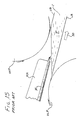
- Injection-fed installations as illustrated in FIG. 13 are commonly presupposed to run with the moving mold full of metal and hence instrumentation to determine the level of the metal is commonly regarded as unnecessary.
- the mold under conditions of injection feeding, the mold is not visible, and with some alloys, when the mold does not run full, metallurgical problems may result in the product.
- one cause is apt to be that one or more passages for the feeding of molten metal through the nosepiece have become clogged with foreign matter, such as aluminum oxide in the case of aluminum casting.
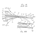
- a thermal sensing probe at or near the beginning of the mold, notably against the top belt, can detect a gaseous void G forming in the mold (FIGS.
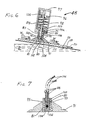
- the emerging frozen product is F (FIG. 1 ).
- the direction of movement of the frozen product F and typically of the liquid coolant W (FIG. 6 ) is shown by arrows, which direction is designated downstream .
- the backup rollers are BR
- the moving edge dams are ED .
- thermocouple 104 (FIGS. 5 , 6 , and 7 ) is the preferred sensing element. Other thermocouple pairs may be used. Alternatively, a small thermistor may be used, with appropriately altered input circuitry in the electronic processor.
- a contact sleeve 100 (FIG. 7 ) of highly heat-conductive material such as copper encompasses the thermocouple junction 104 . This conductive sleeve 100 has a closed end 102 (FIG. 7 ), which is intended to touch the casting belt UB , as shown in FIG 6 .
- the thermocouple 104 and the sleeve 100 are secured together with a potting compound such as epoxy plastic resin 108 (FIG. 7 ).
- cylindrical sleeve 83 (FIG. 5 ), which may be of brass.
- a protective streamlined wear shoe or skate 91 of an extra hard substance is secured to the brass sleeve 83 by cap screw 81 , as seen in FIG. 7 .
- a carbide such as tungsten carbide, or hardened stainless steel such as full-hardened 440C, may be used for the skate 91 , in order to endure for a sufficient period of continuous sliding against the reverse side of the casting belt UB , for protecting the closed end 102 of the copper sleeve 100 meanwhile against too rapid wear. As shown most clearly in FIG.
- the electronic process controller with a circuit designed for automatic operation is shown schematically in FIG. 16 as set up for only one thermal sensor or probe 48 or 62 that bears or skates against the casting belt.
- the components and electrical quantities mentioned below are illustrative examples of one successful installation.
- the signal from the thermal sensor 48 is a weak DC signal of millivolts and microamperes. This weak signal goes to a thermocouple transmitter 201 .
- the transmitter 201 amplifies and transforms the weak signal (or signals if more than one sensor) to an amperage varying from 4 to 20 milliamperes.
- the resulting signal from the transmitter 201 is a single-channel signal (it is a combined unitary outpout signal of the thermal sensors, when there is more than one sensor).
- the single-channel signal enters filter 202 , whence it emerges as a signal of up to 10 millivolts.
- the filtered signal enters the digital single-loop controller indicated generally at 204 , which may be a Leeds & Northrup Electromax 5+.
- the signal first goes to the comparator point 206 where an adjustable "set point" voltage from potentiometer (or digital reference pont) 207 is subtracted, in order to establish the desired set-point CP (FIGS. 10 and 11 ) for pool level control.
- the resulting output is displayed at 208 .
- This output is also amplified at 209 and put through an automatic/manual switch 210 .
- An alarm signal device 205 for example, a light plus a bell--is associated with the process display 208 for giving an alarm warning when the thermal sensor 48 or 62 happens to transmit a signal indicating a temperature being sensed which is above or below the predetermined maximum and minimum values preselected in relation to the desired selected control point CP (FIG. 10 ) and relating to the ramp of temperature R (FIG. 11 ).
- Feedback of the position of cylinder 222 comes from a linear, sliding, conductive plastic potentiometer 224 . Its signal goes through an adjustment at process control station 226 , where a null adjusting potentiometer 227 is used to establish at commissioning the preferred steady-state set-point for the location of the stopper rod 224 .
- the modified signal from flow-control set-point station 226 is fed to the comparator 212 to be compared with the pool-level indication that originated at thermal sensor 48 or 62 . That comparison at 212 completes the internal feedback control loop 214 , and at the same time completes the external feedback control loop involving molten metal and mechanical hardware, so that automatic control of metal level is achieved.
- the feedback signal of stopper-rod metal flow control position from potentiometer 224 as modified at 226 is amplified at 229 and displayed at 228 , on a vertical bar scale consisting of a multiplicity of vertically stacked light-emitting diodes.
- Coarse-fine circuit 230 will, when switched to "fine,” magnify a section of the bar-scale display 228 to obtain a very sensitive readout of the position of stopper-rod 224 .
- All electrical and electronic controls are advantageously centralized at one location for the purpose, for instance, of facilitating and synchronizing the automation of a casting and rolling line.
- Apparatus similar to the electronic and hydraulic control equipment just described apply also to the feeding of molten metal into the tundisch T that in turn feeds metal to the casting machine, as in the control of a tilting holding furnace.
- an optional modification 62 (FIG. 9 ) now under study is to mount a simpler thermal sensing probe on a cantilever beam spring, as shown in FIG. 9 .
- Such an assembly 62 may be discarded when worn out.
- the base 34 holds the insert 132 , to which is firmly fastened the extra hard shoe or skate 138 .
- This shoe may be advantageously made from a small reversible tungsten carbide tool bit, with the protruding sides ground slightly for streamlining in the direction of water flow.
- the thermocouple 130 terminates the lead wires 136 .
- the whole "throw-away probe” is mounted on a cantilever metal spring 144 and removably secured with a pin 146 .
- An advantage of the throwaway probe is that frequent inspection is not so necessary; in this respect, this modification shown in FIG. 9 is unlike the probe described above with its plunger 83 which, if allowed to wear too far, must be replaced, plunger mechanism and all.
- thermal sensing probes 48 there are four thermal sensing probes 48 having their shoes 91 in sliding contact with the reverse surface of the upper belt UB .
- One of these sensors 48 is located between the first two backup rollers BR for the upper belt.
- the other three sensors 48 have their housings 89 secured to a support arm 52 projecting in an upstream direction from a transverse support tube 85 attached at each end to a yoke 148 .
- the support arm 52 extends into a circumferential groove 54 in the upstream upper pulley UUP .
- thermocouple sensor 48 or 62 is calibrated and plotted according to the temperature values shown along the vertical line at left.
- the optical sensor record is plotted at the same relative scale of size as the thermocouple record for purposes of comparison, but is not calibrated with respect to temperature marks on the vertical scale.
- the record of the optics sensor may be regarded as relatively accurate for present purposes. The two records will be seen to correlate closely, thereby illustrating the usefulness of the thermal sensing probe, especially in instances where the optical probe cannot be used.
Landscapes
- Engineering & Computer Science (AREA)
- Mechanical Engineering (AREA)
- Continuous Casting (AREA)
- Control Of Non-Electrical Variables (AREA)
Priority Applications (1)
| Application Number | Priority Date | Filing Date | Title |
|---|---|---|---|
| AT87113253T ATE65197T1 (de) | 1986-09-11 | 1987-09-10 | Verfahren zur automatischen fuellstandskontrolle fuer doppelband-stranggussmaschinen. |
Applications Claiming Priority (2)
| Application Number | Priority Date | Filing Date | Title |
|---|---|---|---|
| US06/906,256 US4712602A (en) | 1986-09-11 | 1986-09-11 | Pool-level sensing probe and automatic level control for twin-belt continuous metal casting machines |
| US906256 | 1986-09-11 |
Publications (3)
| Publication Number | Publication Date |
|---|---|
| EP0259876A2 true EP0259876A2 (fr) | 1988-03-16 |
| EP0259876A3 EP0259876A3 (en) | 1988-07-06 |
| EP0259876B1 EP0259876B1 (fr) | 1991-07-17 |
Family
ID=25422156
Family Applications (1)
| Application Number | Title | Priority Date | Filing Date |
|---|---|---|---|
| EP87113253A Expired - Lifetime EP0259876B1 (fr) | 1986-09-11 | 1987-09-10 | Procédé pour commande automatique du niveau pour des machines à coulée continue à double bande |
Country Status (6)
| Country | Link |
|---|---|
| US (1) | US4712602A (fr) |
| EP (1) | EP0259876B1 (fr) |
| JP (1) | JPS63101055A (fr) |
| AT (1) | ATE65197T1 (fr) |
| CA (1) | CA1308875C (fr) |
| DE (1) | DE3771424D1 (fr) |
Families Citing this family (9)
| Publication number | Priority date | Publication date | Assignee | Title |
|---|---|---|---|---|
| US4813471A (en) * | 1988-05-05 | 1989-03-21 | Hazelett Strip-Casting Corporation | Method for determining molten metal pool level in twin-belt continuous casting machines |
| US5804136A (en) * | 1996-11-27 | 1998-09-08 | Hazelett Strip-Casting Corporation | Radial-flow distributor for wide uniform nonturbulent non-dribbling pouring of molten metal into a continuous metal-casting machine-methods and apparatus |
| JP2000121508A (ja) * | 1998-10-15 | 2000-04-28 | Tlv Co Ltd | 電源を内蔵するモニタリング・システム |
| US7888158B1 (en) * | 2009-07-21 | 2011-02-15 | Sears Jr James B | System and method for making a photovoltaic unit |
| US20110036530A1 (en) * | 2009-08-11 | 2011-02-17 | Sears Jr James B | System and Method for Integrally Casting Multilayer Metallic Structures |
| US20110036531A1 (en) * | 2009-08-11 | 2011-02-17 | Sears Jr James B | System and Method for Integrally Casting Multilayer Metallic Structures |
| US8408280B1 (en) * | 2012-02-17 | 2013-04-02 | Wagstaff, Inc. | Bleedout detection system |
| US11000893B2 (en) | 2017-04-11 | 2021-05-11 | Hazelett Strip-Casting Corporation | System and method for continuous casting |
| CN121199088B (zh) * | 2025-11-26 | 2026-02-17 | 龙门实验室 | 一种双带式铝材铸造机及其铸造工艺 |
Family Cites Families (6)
| Publication number | Priority date | Publication date | Assignee | Title |
|---|---|---|---|---|
| US3921697A (en) * | 1973-03-22 | 1975-11-25 | Hazelett Strip Casting Corp | Method and apparatus for controlling the operating conditions in continuous metal casting machines having a revolving endless casting belt |
| US3864973A (en) * | 1973-03-22 | 1975-02-11 | Hazelett Strip Casting Corp | Method and apparatus for determining the operating conditions in continuous metal casting machines of the type having a revolving endless casting belt |
| LU79390A1 (fr) * | 1978-04-06 | 1979-11-07 | Metallurgie Hoboken | Procede de coulee continue d'un metal et appareil pour sa mise en oeuvre |
| DE3248473A1 (de) * | 1982-12-29 | 1984-07-12 | Fried. Krupp Gmbh, 4300 Essen | Verfahren zum zufuehren von stahlschmelze in eine giessvorrichtung mit in giessrichtung bewegten kokillenwaenden und zufuehrvorrichtung zur durchfuehrung des verfahrens |
| US4570230A (en) * | 1983-03-28 | 1986-02-11 | United States Steel Corporation | Method of measuring and controlling the level of liquid in a container |
| DE3409910A1 (de) * | 1984-03-17 | 1985-04-25 | Fried. Krupp Gmbh, 4300 Essen | Verfahren zum betrieb einer doppelbandstranggiesskokille zum druckgiessen von stahl und mit einer doppelbandstranggiesskokille zusammenwirkende giessduese zur durchfuehrung des verfahrens |
-
1986
- 1986-09-11 US US06/906,256 patent/US4712602A/en not_active Expired - Lifetime
-
1987
- 1987-09-10 DE DE8787113253T patent/DE3771424D1/de not_active Expired - Fee Related
- 1987-09-10 EP EP87113253A patent/EP0259876B1/fr not_active Expired - Lifetime
- 1987-09-10 AT AT87113253T patent/ATE65197T1/de not_active IP Right Cessation
- 1987-09-11 CA CA000546497A patent/CA1308875C/fr not_active Expired - Fee Related
- 1987-09-11 JP JP62228243A patent/JPS63101055A/ja active Pending
Also Published As
| Publication number | Publication date |
|---|---|
| ATE65197T1 (de) | 1991-08-15 |
| DE3771424D1 (de) | 1991-08-22 |
| US4712602A (en) | 1987-12-15 |
| JPS63101055A (ja) | 1988-05-06 |
| CA1308875C (fr) | 1992-10-20 |
| EP0259876B1 (fr) | 1991-07-17 |
| EP0259876A3 (en) | 1988-07-06 |
Similar Documents
| Publication | Publication Date | Title |
|---|---|---|
| US3921697A (en) | Method and apparatus for controlling the operating conditions in continuous metal casting machines having a revolving endless casting belt | |
| US5158128A (en) | Thermocouple for a continuous casting machine | |
| US4553604A (en) | Method of controlling continuous casting equipment | |
| US3864973A (en) | Method and apparatus for determining the operating conditions in continuous metal casting machines of the type having a revolving endless casting belt | |
| EP1962071B1 (fr) | Système de mesure de température | |
| EP0259876B1 (fr) | Procédé pour commande automatique du niveau pour des machines à coulée continue à double bande | |
| KR960003717B1 (ko) | 파괴가능성 검출과 연속주조방법 및 그 장치와 주형벽 온도 측정장치 | |
| KR20190135451A (ko) | 용융 금속 욕의 온도 측정 방법 | |
| US6776217B1 (en) | Method for continuous casting of slab, in particular, thin slab, and a device for performing the method | |
| CA2025153A1 (fr) | Procede permettant de determiner, en continu, l'epaisseur d'un laitier assez liquide a la surface d'un bain de metal fondu se trouvant dans un contenant metallurgique | |
| JPS6353903B2 (fr) | ||
| US3528479A (en) | Control system for regulating flow of molten metal into a continuously rotated casting wheel | |
| JPH09225613A (ja) | 薄板連続鋳造用ロールの冷却方法 | |
| JP2002248547A (ja) | 溶湯の供給装置および供給方法 | |
| JPS6353904B2 (fr) | ||
| KR960007494B1 (ko) | 주조 노즐과 기체(基體)의 주조 표면 사이의 틈을 모니터하는 장치 및 방법 | |
| CA1328925C (fr) | Procede de coulee continue avec detection de possibilite de defaut de moulage | |
| JPH0976050A (ja) | モールドパウダー厚の制御方法および装置 | |
| CA1185064A (fr) | Controle de l'interface liquide-solide en coulee electromagnetique | |
| US3456714A (en) | Casting level-control device for a continuous casting installation | |
| JPH0557415A (ja) | 連続鋳造装置の2次冷却状態を制御するセンサーと、このセンサーを備えたダミーバーと、連続鋳造装置の制御方法 | |
| KR100803733B1 (ko) | 용융 몰드플럭스를 이용한 연속 주조에 사용하는 탕면 레벨측정 센서 유닛 | |
| JP2914817B2 (ja) | 連続鋳造における欠落鋳造方法 | |
| KR100793936B1 (ko) | 용융 몰드플럭스 두께 측정 장치 및 방법 | |
| JPH06320245A (ja) | モールド内抜熱制御装置 |
Legal Events
| Date | Code | Title | Description |
|---|---|---|---|
| PUAI | Public reference made under article 153(3) epc to a published international application that has entered the european phase |
Free format text: ORIGINAL CODE: 0009012 |
|
| AK | Designated contracting states |
Kind code of ref document: A2 Designated state(s): AT BE DE FR GB IT NL SE |
|
| PUAL | Search report despatched |
Free format text: ORIGINAL CODE: 0009013 |
|
| AK | Designated contracting states |
Kind code of ref document: A3 Designated state(s): AT BE DE FR GB IT NL SE |
|
| 17P | Request for examination filed |
Effective date: 19890105 |
|
| 17Q | First examination report despatched |
Effective date: 19890823 |
|
| GRAA | (expected) grant |
Free format text: ORIGINAL CODE: 0009210 |
|
| AK | Designated contracting states |
Kind code of ref document: B1 Designated state(s): AT BE DE FR GB IT NL SE |
|
| PG25 | Lapsed in a contracting state [announced via postgrant information from national office to epo] |
Ref country code: SE Effective date: 19910717 Ref country code: AT Effective date: 19910717 |
|
| REF | Corresponds to: |
Ref document number: 65197 Country of ref document: AT Date of ref document: 19910815 Kind code of ref document: T |
|
| ET | Fr: translation filed | ||
| REF | Corresponds to: |
Ref document number: 3771424 Country of ref document: DE Date of ref document: 19910822 |
|
| PGFP | Annual fee paid to national office [announced via postgrant information from national office to epo] |
Ref country code: SE Payment date: 19910906 Year of fee payment: 5 |
|
| PGFP | Annual fee paid to national office [announced via postgrant information from national office to epo] |
Ref country code: AT Payment date: 19910909 Year of fee payment: 5 |
|
| ITF | It: translation for a ep patent filed | ||
| PG25 | Lapsed in a contracting state [announced via postgrant information from national office to epo] |
Ref country code: NL Effective date: 19911101 |
|
| PLBE | No opposition filed within time limit |
Free format text: ORIGINAL CODE: 0009261 |
|
| STAA | Information on the status of an ep patent application or granted ep patent |
Free format text: STATUS: NO OPPOSITION FILED WITHIN TIME LIMIT |
|
| 26N | No opposition filed | ||
| PGFP | Annual fee paid to national office [announced via postgrant information from national office to epo] |
Ref country code: GB Payment date: 19930901 Year of fee payment: 7 |
|
| PGFP | Annual fee paid to national office [announced via postgrant information from national office to epo] |
Ref country code: DE Payment date: 19930908 Year of fee payment: 7 |
|
| PGFP | Annual fee paid to national office [announced via postgrant information from national office to epo] |
Ref country code: FR Payment date: 19930909 Year of fee payment: 7 |
|
| PGFP | Annual fee paid to national office [announced via postgrant information from national office to epo] |
Ref country code: BE Payment date: 19931012 Year of fee payment: 7 |
|
| PG25 | Lapsed in a contracting state [announced via postgrant information from national office to epo] |
Ref country code: GB Effective date: 19940910 |
|
| PG25 | Lapsed in a contracting state [announced via postgrant information from national office to epo] |
Ref country code: BE Effective date: 19940930 |
|
| BERE | Be: lapsed |
Owner name: HAZELETT STRIP-CASTING CORP. Effective date: 19940930 |
|
| GBPC | Gb: european patent ceased through non-payment of renewal fee |
Effective date: 19940910 |
|
| PG25 | Lapsed in a contracting state [announced via postgrant information from national office to epo] |
Ref country code: FR Effective date: 19950531 |
|
| PG25 | Lapsed in a contracting state [announced via postgrant information from national office to epo] |
Ref country code: DE Effective date: 19950601 |
|
| REG | Reference to a national code |
Ref country code: FR Ref legal event code: ST |
|
| ET | Fr: translation filed | ||
| PG25 | Lapsed in a contracting state [announced via postgrant information from national office to epo] |
Ref country code: IT Free format text: LAPSE BECAUSE OF NON-PAYMENT OF DUE FEES Effective date: 20050910 |