EP0259903B1 - Vorrichtung zum Bewegen von Kübeln in einer Zuführzone für Schrott - Google Patents
Vorrichtung zum Bewegen von Kübeln in einer Zuführzone für Schrott Download PDFInfo
- Publication number
- EP0259903B1 EP0259903B1 EP87201442A EP87201442A EP0259903B1 EP 0259903 B1 EP0259903 B1 EP 0259903B1 EP 87201442 A EP87201442 A EP 87201442A EP 87201442 A EP87201442 A EP 87201442A EP 0259903 B1 EP0259903 B1 EP 0259903B1
- Authority
- EP
- European Patent Office
- Prior art keywords
- skip
- legs
- station
- press
- support
- Prior art date
- Legal status (The legal status is an assumption and is not a legal conclusion. Google has not performed a legal analysis and makes no representation as to the accuracy of the status listed.)
- Expired - Lifetime
Links
- 238000000034 method Methods 0.000 claims abstract description 10
- 238000003825 pressing Methods 0.000 claims abstract description 4
- 230000000284 resting effect Effects 0.000 claims 2
- 230000007246 mechanism Effects 0.000 description 2
- 238000005303 weighing Methods 0.000 description 2
- 238000003723 Smelting Methods 0.000 description 1
- 238000005056 compaction Methods 0.000 description 1
- 238000007599 discharging Methods 0.000 description 1
Images

Classifications
-
- B—PERFORMING OPERATIONS; TRANSPORTING
- B60—VEHICLES IN GENERAL
- B60P—VEHICLES ADAPTED FOR LOAD TRANSPORTATION OR TO TRANSPORT, TO CARRY, OR TO COMPRISE SPECIAL LOADS OR OBJECTS
- B60P1/00—Vehicles predominantly for transporting loads and modified to facilitate loading, consolidating the load, or unloading
- B60P1/02—Vehicles predominantly for transporting loads and modified to facilitate loading, consolidating the load, or unloading with parallel up-and-down movement of load supporting or containing element
- B60P1/025—Vehicles predominantly for transporting loads and modified to facilitate loading, consolidating the load, or unloading with parallel up-and-down movement of load supporting or containing element with a loading platform inside the wheels of a same axle and being lowerable below the axle
-
- B—PERFORMING OPERATIONS; TRANSPORTING
- B30—PRESSES
- B30B—PRESSES IN GENERAL
- B30B9/00—Presses specially adapted for particular purposes
- B30B9/32—Presses specially adapted for particular purposes for consolidating scrap metal or for compacting used cars
- B30B9/328—Presses specially adapted for particular purposes for consolidating scrap metal or for compacting used cars for making furnace charges
Definitions
- This invention concerns a device to move skips in the scrap charging zone and also concerns a method, arising from the employment of such device, for the movement of skips.
- Steelworks have for some time now been practising a method of charging skips with scrap which enables the skips to be filled to the maximum extent possible, the purpose being to speed up the operations of charging smelting furnaces.
- a cradle has also been pre-arranged which accommodates the base of the skips, holds them and positions them.
- cradle covers a very wide range of supports for skips undergoing press action. Such cradle serves also to move the skips within a given limited scope.
- the skip is normally borne on an appropriate support or pallet with legs, which also serves normally for the weighing of the charge.
- Such support with legs enables the skip to be moved along long tracts by means of appropriate vehicles having substantially one single surface with a vertically movable platform.
- appropriate vehicles having substantially one single surface with a vertically movable platform.
- Such vehicles are introduced between the legs of the support, raise their platform, lift the support with the skip thereupon and move this assemblage wherever it is required.
- US-A-4,470,580 discloses a press for scrap with a two-dimensional press die and a means to position and support the skip.
- the means to position and support the skip is a movable carriage with means to transfer the carriage itself, which runs on its own runways.
- US-A-3,416,436 discloses a scrap press cooperating with at least one charging and discharging station, the skip holding the scrap being moved on guides from that station to the press and back; the press is equipped with an extractor jack.
- US-A-4,568,236 discloses a trailer with a movable platform to move heavy loads on roads and highways.
- EP-A-0.035.568 discloses a press to make briquettes, in which a carriage holding a mould cooperates with the press itself.
- the invention enables the yard employed for the movement of skips to be kept free of cranes or other transport means; it enables very short handling times to be obtained and permits the required skip to be conveyed to the press zone and to be pressed as needed; it enables the working cycle to be simplified in the zone of charging and pressing the skip.
- a trolley device with two side members is provided.
- Such trolley device comprises two side frame members with vertically movable bars able to cooperate with the base of containment housings which contain, for instance, the mechanisms for opening the lower hinged discharge flaps of the skip.
- a cradle remains stationary under the press and the trolley device handles the skip.
- the trolley device may comprise rubber wheels for its movement or wheels suitable for running on rails.
- the movement of the trolley may be carried out by independent means or by cables, that is to say, a pair of endless cables on the trolley device serve to move it to-and-fro.
- the invention is therefore embodied with a device to move skips in a scrap charging zone providing at least one charging station and a station to press the scrap within the skip, the skip being borne by an independent support with legs in the charging station and being supported on a cradle in the press station and comprising containment housings in diametrically opposite positions, the median vertical plane of the press being substantially normal to the lengthwise axis of movement of the skip, the device being characterized in that it is of a trolley type with two side frame members, each of which comprises an upper bar able to move vertically at least between an inactive position and a working position, the upper bars cooperating with the containment housings.
- the invention is also obtained with a method to move skips in a scrap charging zone providing at least one charging station and a station to press the scrap within the skip, the skip being borne by an independent support with legs in the charging station and being supported on a cradle in the press station and comprising containment housings laterally for the opening of lower hinged discharge flaps of the skip, the median vertical plane of the press being substantially normal to the lengthwise axis of movement of the skip, the method being characterized in that a skip full of scrap is lifted and withdrawn from its support with legs by a trolley device and taken by such device from the charging station or from a parking station for skips and placed on a cradle comprised in cooperation with a press for the pressing of scrap.
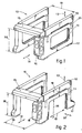
- a trolley device 10 comprises two side frame members II on which are included two vertically movable bars 12. The vertical movement of such bars 12 is obtained with jacks 35 contained, for instance, in the side frame members II.
- the bars 12 can therefore be raised and lowered according to the arrows 13, thus taking up an inactive position when they are lowered and a working position when they are raised.
- the trolley device 10 can pass beneath containment housings 26 of skips 25 when the skips 25 are rested on supports with legs 24, the housings 26 protruding substantially from the skips.
- the trolley device 10 comprises a main frame member 15 which connects the two side frame members II, thus stiffening the trolley device 10.
- the trolley device 10 comprises also wheels 17 and a control and driving cab 16.
- the inner width 19 of the trolley device 10 is greater than the outer width of the support with legs 24, the support having a substantially square floor plan, so that the trolley device 10 can pass completely with its side members II running outside the sides of the support 24 since the height 36 of the main frame member 15 is greater than the height of the support 24.
- the outer width of the trolley device 10 is smaller than the inner width of a press 27, so that the trolley device 10 can run between side frame members of the press 27.
- the trolley device 10 can move to-and-fro as required according to the arrows 14, and the inclusion of the cab 16 facilitates operations.
- the side frame members II of the trolley may be arranged so that their height 18 is less than the height between the support surface of the support with legs 24 and the lower surface of the mechanism containment housings 26.
- the side frame members II will comprise advantageously a portal shaped as an inverted "U” and having a free vertical height 36 greater than the height of the support with legs 24 and a free width 19 greater than the width of the support 24 (see Fig.2), so that the support with legs 24 borne on a vehicle 30 can pass between the legs of the side frame members 18 of the trolley 10.
- the support with legs 24 can be displaced sideways according to the arrows 37 and thus can be removed crosswise through the side frame members II of the trolley by a vehicle 30 having a movable platform.
- a press 27 is provided substantially on the same axis as the skip charging station 31.
- various charging stations 31 may be comprised and be equipped with a support with legs 24 cooperating with a weighing machine 23.
- the supports with legs 24 are able to move and can be moved anywhere; they may be stationary in the charging stations 31 alone.
- Each of the charging stations 31 cooperates with a pit 21 for scrap and is equipped with charging grabs 22.
- the skip 25 is delivered in the press station 32 to a lifting system 29 of a type protected by a parallel application filed by the present applicant.
- lifting system 29 cooperates with eyelets 38 provided at the sides or top of the skip 25.
- the skip 25 is taken once more by the trolley device 10 and moved thereby to a parking station 33 for skips, where a support with legs 24 is ready to accommodate it.
- the support with legs 24 may already be ready in the parking station 33.
- the vehicle 30 holding the support 24 passes through the device 10 crosswise and has the support 24 ready and positioned for delivery of skips 25.
- the device 10 then moves to a parking station 34 whenever it includes the main frame member 15.
- a skip 25 When a skip 25 arrives at the parking station 33, it may be full of scrap to be pressed or may be empty so as to replace a skip 25 already present in the skip charging station 31 or already pressed and removed.
- a support 24 freed of a skip may be removed by the vehicle 30 even if the device 10 is in the parking station 33.
- the device 10 may not comprise the main frame member 15; in such an event the two side frame members 11 are self-aligning in relation to each other.
Landscapes
- Engineering & Computer Science (AREA)
- Mechanical Engineering (AREA)
- Transportation (AREA)
- Refuse Collection And Transfer (AREA)
- Automatic Analysis And Handling Materials Therefor (AREA)
- Container Filling Or Packaging Operations (AREA)
- Supplying Of Containers To The Packaging Station (AREA)
- Feeding, Discharge, Calcimining, Fusing, And Gas-Generation Devices (AREA)
- Filling Or Emptying Of Bunkers, Hoppers, And Tanks (AREA)
- Manufacture And Refinement Of Metals (AREA)
- Press Drives And Press Lines (AREA)
- Centrifugal Separators (AREA)
- Load-Engaging Elements For Cranes (AREA)
Claims (12)
Priority Applications (1)
| Application Number | Priority Date | Filing Date | Title |
|---|---|---|---|
| AT87201442T ATE57134T1 (de) | 1986-09-02 | 1987-07-27 | Vorrichtung zum bewegen von kuebeln in einer zufuehrzone fuer schrott. |
Applications Claiming Priority (2)
| Application Number | Priority Date | Filing Date | Title |
|---|---|---|---|
| IT8339886 | 1986-09-02 | ||
| IT83398/86A IT1201805B (it) | 1986-09-02 | 1986-09-02 | Dispositivo movimentazione cesta in zona carico rottami |
Publications (2)
| Publication Number | Publication Date |
|---|---|
| EP0259903A1 EP0259903A1 (de) | 1988-03-16 |
| EP0259903B1 true EP0259903B1 (de) | 1990-10-03 |
Family
ID=11321297
Family Applications (1)
| Application Number | Title | Priority Date | Filing Date |
|---|---|---|---|
| EP87201442A Expired - Lifetime EP0259903B1 (de) | 1986-09-02 | 1987-07-27 | Vorrichtung zum Bewegen von Kübeln in einer Zuführzone für Schrott |
Country Status (6)
| Country | Link |
|---|---|
| US (1) | US4815371A (de) |
| EP (1) | EP0259903B1 (de) |
| AT (1) | ATE57134T1 (de) |
| DE (1) | DE3765372D1 (de) |
| ES (1) | ES2014194B3 (de) |
| IT (1) | IT1201805B (de) |
Families Citing this family (2)
| Publication number | Priority date | Publication date | Assignee | Title |
|---|---|---|---|---|
| US6521177B1 (en) | 2000-03-29 | 2003-02-18 | Galt Alloys, Inc. | Process for compounding titanium alloys |
| US7198452B2 (en) * | 2004-04-08 | 2007-04-03 | Ocenco, Inc. | Bar stock loading table and apparatus |
Family Cites Families (8)
| Publication number | Priority date | Publication date | Assignee | Title |
|---|---|---|---|---|
| US3386375A (en) * | 1965-12-21 | 1968-06-04 | Tezuka Kunitoshi | Device for removing materials from a compressor |
| US3460363A (en) * | 1966-03-04 | 1969-08-12 | Frederick W Grantham | Laundry extractor |
| US3416436A (en) * | 1966-03-29 | 1968-12-17 | Tezuka Kunitoshi | Scrap-metal compressor |
| BE759172A (fr) * | 1970-09-19 | 1971-04-30 | Nippon Kokan Kk | Appareil pour comprimer la mitraille en un bloc et transporter celui-c |
| US4068577A (en) * | 1976-03-15 | 1978-01-17 | Patrick Joseph Murphy | Work positioning table |
| JPS55140512A (en) * | 1979-04-20 | 1980-11-04 | Mitsuishi Fukai Iron Works | Molding machine used for brick* etc* |
| US4568236A (en) * | 1982-07-23 | 1986-02-04 | Eugene A. LeBoeuf | Lift bed pallet highway trailer |
| US4470580A (en) * | 1983-05-27 | 1984-09-11 | Officine Vezzani S.P.A. | Method and apparatus for preparing scrap metal charges for smelting furnaces |
-
1986
- 1986-09-02 IT IT83398/86A patent/IT1201805B/it active
-
1987
- 1987-07-27 AT AT87201442T patent/ATE57134T1/de not_active IP Right Cessation
- 1987-07-27 DE DE8787201442T patent/DE3765372D1/de not_active Expired - Fee Related
- 1987-07-27 ES ES87201442T patent/ES2014194B3/es not_active Expired - Lifetime
- 1987-07-27 EP EP87201442A patent/EP0259903B1/de not_active Expired - Lifetime
- 1987-08-06 US US07/082,215 patent/US4815371A/en not_active Expired - Fee Related
Also Published As
| Publication number | Publication date |
|---|---|
| IT1201805B (it) | 1989-02-02 |
| IT8683398A0 (it) | 1986-09-02 |
| US4815371A (en) | 1989-03-28 |
| DE3765372D1 (de) | 1990-11-08 |
| ES2014194B3 (es) | 1991-04-16 |
| ES2014194A4 (es) | 1990-07-01 |
| ATE57134T1 (de) | 1990-10-15 |
| EP0259903A1 (de) | 1988-03-16 |
Similar Documents
| Publication | Publication Date | Title |
|---|---|---|
| JPH05337760A (ja) | ワーク搬送システム及び該システムに好適に用いられるパレット搬送装置 | |
| US3212654A (en) | Apparatus for loading and unloading goods | |
| EP0030928A1 (de) | Einrichtung zum Ein- und Auslagern von sperrigen oder schweren Gegenständen | |
| CN214652158U (zh) | 自动装车系统 | |
| US4815371A (en) | Method for pressing scrap in a skip | |
| SE7604592L (sv) | Transportanleggning for horisontal- och vertikaltransport | |
| US4135631A (en) | Freight train | |
| CN111842869B (zh) | 一种钢水集成处理装置及其系统 | |
| CN222249185U (zh) | 一种废钢斗升降翻倒装置 | |
| EP0573380A1 (de) | Einrichtung zum Manövrieren von Paletten in Portalkränen | |
| CN210001536U (zh) | 一种自动取投料agv小车 | |
| EP0260730B1 (de) | Pressen zum Pressen von Schrott in Gichtkübeln und Verfahren zum Bewegen von Gichtkübeln unter den Pressen | |
| US3446269A (en) | Apparatus for the transporting of the intermediate container of continuous casting machines | |
| US3487957A (en) | Charging apparatus | |
| CN118183550A (zh) | 一种物料转运装置及其使用方法 | |
| US4081089A (en) | Arrangement for handling and preparation of base plates and the like such as, for example, casting molds | |
| US3592348A (en) | Load carrier-load support mechanism in automatic warehousing system | |
| US3741418A (en) | Materials handling vehicle | |
| CN211444884U (zh) | 升降踏板车 | |
| DE3828962A1 (de) | Stahlwerksanlage mit einem metallurgischen ofen und einer weiterverarbeitungsanlage | |
| DE4311146A1 (de) | Schnellumschlagterminal | |
| CN224198757U (zh) | 一种自动化粉料投料装置 | |
| CN217675084U (zh) | 一种铁路车轮检修电动输送车 | |
| CN220182684U (zh) | 一种便于定位的托盘堆垛车 | |
| US3489301A (en) | Method and apparatus for handling scrap metal |
Legal Events
| Date | Code | Title | Description |
|---|---|---|---|
| PUAI | Public reference made under article 153(3) epc to a published international application that has entered the european phase |
Free format text: ORIGINAL CODE: 0009012 |
|
| AK | Designated contracting states |
Kind code of ref document: A1 Designated state(s): AT BE CH DE ES FR GB GR LI LU NL SE |
|
| 17P | Request for examination filed |
Effective date: 19880826 |
|
| 17Q | First examination report despatched |
Effective date: 19900207 |
|
| GRAA | (expected) grant |
Free format text: ORIGINAL CODE: 0009210 |
|
| AK | Designated contracting states |
Kind code of ref document: B1 Designated state(s): AT BE CH DE ES FR GB GR LI LU NL SE |
|
| PG25 | Lapsed in a contracting state [announced via postgrant information from national office to epo] |
Ref country code: SE Effective date: 19901003 Ref country code: NL Effective date: 19901003 Ref country code: LI Effective date: 19901003 Ref country code: GR Free format text: LAPSE BECAUSE OF FAILURE TO SUBMIT A TRANSLATION OF THE DESCRIPTION OR TO PAY THE FEE WITHIN THE PRESCRIBED TIME-LIMIT Effective date: 19901003 Ref country code: CH Effective date: 19901003 |
|
| REF | Corresponds to: |
Ref document number: 57134 Country of ref document: AT Date of ref document: 19901015 Kind code of ref document: T |
|
| REF | Corresponds to: |
Ref document number: 3765372 Country of ref document: DE Date of ref document: 19901108 |
|
| ET | Fr: translation filed | ||
| REG | Reference to a national code |
Ref country code: CH Ref legal event code: PL |
|
| NLV1 | Nl: lapsed or annulled due to failure to fulfill the requirements of art. 29p and 29m of the patents act | ||
| PG25 | Lapsed in a contracting state [announced via postgrant information from national office to epo] |
Ref country code: LU Free format text: LAPSE BECAUSE OF NON-PAYMENT OF DUE FEES Effective date: 19910731 |
|
| PLBE | No opposition filed within time limit |
Free format text: ORIGINAL CODE: 0009261 |
|
| STAA | Information on the status of an ep patent application or granted ep patent |
Free format text: STATUS: NO OPPOSITION FILED WITHIN TIME LIMIT |
|
| 26N | No opposition filed | ||
| PGFP | Annual fee paid to national office [announced via postgrant information from national office to epo] |
Ref country code: DE Payment date: 19950705 Year of fee payment: 9 |
|
| PGFP | Annual fee paid to national office [announced via postgrant information from national office to epo] |
Ref country code: BE Payment date: 19950712 Year of fee payment: 9 |
|
| PGFP | Annual fee paid to national office [announced via postgrant information from national office to epo] |
Ref country code: FR Payment date: 19950713 Year of fee payment: 9 |
|
| PGFP | Annual fee paid to national office [announced via postgrant information from national office to epo] |
Ref country code: ES Payment date: 19950714 Year of fee payment: 9 |
|
| PGFP | Annual fee paid to national office [announced via postgrant information from national office to epo] |
Ref country code: GB Payment date: 19950726 Year of fee payment: 9 |
|
| PGFP | Annual fee paid to national office [announced via postgrant information from national office to epo] |
Ref country code: AT Payment date: 19950731 Year of fee payment: 9 |
|
| PG25 | Lapsed in a contracting state [announced via postgrant information from national office to epo] |
Ref country code: GB Effective date: 19960727 Ref country code: AT Effective date: 19960727 |
|
| PG25 | Lapsed in a contracting state [announced via postgrant information from national office to epo] |
Ref country code: ES Free format text: LAPSE BECAUSE OF THE APPLICANT RENOUNCES Effective date: 19960729 |
|
| PG25 | Lapsed in a contracting state [announced via postgrant information from national office to epo] |
Ref country code: BE Effective date: 19960731 |
|
| BERE | Be: lapsed |
Owner name: DANIELI & C. OFFICINE MECCANICHE S.P.A. Effective date: 19960731 |
|
| GBPC | Gb: european patent ceased through non-payment of renewal fee |
Effective date: 19960727 |
|
| PG25 | Lapsed in a contracting state [announced via postgrant information from national office to epo] |
Ref country code: FR Effective date: 19970328 |
|
| PG25 | Lapsed in a contracting state [announced via postgrant information from national office to epo] |
Ref country code: DE Effective date: 19970402 |
|
| REG | Reference to a national code |
Ref country code: FR Ref legal event code: ST |
|
| REG | Reference to a national code |
Ref country code: ES Ref legal event code: FD2A Effective date: 19991007 |