EP0259906B1 - Système de stimulation d'au moins un nerf et/ou fibre d'un muscle - Google Patents
Système de stimulation d'au moins un nerf et/ou fibre d'un muscle Download PDFInfo
- Publication number
- EP0259906B1 EP0259906B1 EP87201505A EP87201505A EP0259906B1 EP 0259906 B1 EP0259906 B1 EP 0259906B1 EP 87201505 A EP87201505 A EP 87201505A EP 87201505 A EP87201505 A EP 87201505A EP 0259906 B1 EP0259906 B1 EP 0259906B1
- Authority
- EP
- European Patent Office
- Prior art keywords
- stimulating
- subject
- stimulating system
- implant
- receiving unit
- Prior art date
- Legal status (The legal status is an assumption and is not a legal conclusion. Google has not performed a legal analysis and makes no representation as to the accuracy of the status listed.)
- Expired - Lifetime
Links
- 230000004936 stimulating effect Effects 0.000 title claims abstract description 34
- 210000005036 nerve Anatomy 0.000 title claims abstract description 10
- 239000000835 fiber Substances 0.000 title claims abstract description 7
- 210000003205 muscle Anatomy 0.000 title claims abstract description 7
- 239000007943 implant Substances 0.000 claims abstract description 23
- 210000003477 cochlea Anatomy 0.000 claims abstract description 8
- 239000011521 glass Substances 0.000 claims description 6
- 230000005855 radiation Effects 0.000 claims description 6
- 230000001939 inductive effect Effects 0.000 claims description 3
- 238000004804 winding Methods 0.000 claims description 3
- RTAQQCXQSZGOHL-UHFFFAOYSA-N Titanium Chemical group [Ti] RTAQQCXQSZGOHL-UHFFFAOYSA-N 0.000 claims description 2
- 229910010293 ceramic material Inorganic materials 0.000 claims description 2
- 239000000463 material Substances 0.000 claims description 2
- 229910052710 silicon Inorganic materials 0.000 claims description 2
- 239000010703 silicon Substances 0.000 claims description 2
- 239000000560 biocompatible material Substances 0.000 claims 1
- 230000005540 biological transmission Effects 0.000 abstract 1
- 230000002051 biphasic effect Effects 0.000 description 4
- 238000002513 implantation Methods 0.000 description 4
- 206010011878 Deafness Diseases 0.000 description 3
- 238000001514 detection method Methods 0.000 description 3
- 230000006870 function Effects 0.000 description 3
- 239000001307 helium Substances 0.000 description 3
- 229910052734 helium Inorganic materials 0.000 description 3
- SWQJXJOGLNCZEY-UHFFFAOYSA-N helium atom Chemical compound [He] SWQJXJOGLNCZEY-UHFFFAOYSA-N 0.000 description 3
- 210000001519 tissue Anatomy 0.000 description 3
- 238000003466 welding Methods 0.000 description 3
- 210000000860 cochlear nerve Anatomy 0.000 description 2
- 239000004020 conductor Substances 0.000 description 2
- 239000007789 gas Substances 0.000 description 2
- 238000001208 nuclear magnetic resonance pulse sequence Methods 0.000 description 2
- BASFCYQUMIYNBI-UHFFFAOYSA-N platinum Chemical compound [Pt] BASFCYQUMIYNBI-UHFFFAOYSA-N 0.000 description 2
- 230000000638 stimulation Effects 0.000 description 2
- 230000001360 synchronised effect Effects 0.000 description 2
- 235000008733 Citrus aurantifolia Nutrition 0.000 description 1
- 235000011941 Tilia x europaea Nutrition 0.000 description 1
- 239000000853 adhesive Substances 0.000 description 1
- 230000001070 adhesive effect Effects 0.000 description 1
- 230000003247 decreasing effect Effects 0.000 description 1
- 238000010586 diagram Methods 0.000 description 1
- 210000003027 ear inner Anatomy 0.000 description 1
- 238000002474 experimental method Methods 0.000 description 1
- 239000012530 fluid Substances 0.000 description 1
- 239000004571 lime Substances 0.000 description 1
- 238000000034 method Methods 0.000 description 1
- 229910052697 platinum Inorganic materials 0.000 description 1
- HWLDNSXPUQTBOD-UHFFFAOYSA-N platinum-iridium alloy Chemical compound [Ir].[Pt] HWLDNSXPUQTBOD-UHFFFAOYSA-N 0.000 description 1
- 238000007789 sealing Methods 0.000 description 1
- 230000035807 sensation Effects 0.000 description 1
- 210000003625 skull Anatomy 0.000 description 1
- 230000009182 swimming Effects 0.000 description 1
- 229910052719 titanium Inorganic materials 0.000 description 1
- 239000010936 titanium Substances 0.000 description 1
Images


Classifications
-
- A—HUMAN NECESSITIES
- A61—MEDICAL OR VETERINARY SCIENCE; HYGIENE
- A61F—FILTERS IMPLANTABLE INTO BLOOD VESSELS; PROSTHESES; DEVICES PROVIDING PATENCY TO, OR PREVENTING COLLAPSING OF, TUBULAR STRUCTURES OF THE BODY, e.g. STENTS; ORTHOPAEDIC, NURSING OR CONTRACEPTIVE DEVICES; FOMENTATION; TREATMENT OR PROTECTION OF EYES OR EARS; BANDAGES, DRESSINGS OR ABSORBENT PADS; FIRST-AID KITS
- A61F11/00—Methods or devices for treatment of the ears or hearing sense; Non-electric hearing aids; Methods or devices for enabling ear patients to achieve auditory perception through physiological senses other than hearing sense; Protective devices for the ears, carried on the body or in the hand
- A61F11/04—Methods or devices for enabling ear patients to achieve auditory perception through physiological senses other than hearing sense, e.g. through the touch sense
-
- A—HUMAN NECESSITIES
- A61—MEDICAL OR VETERINARY SCIENCE; HYGIENE
- A61N—ELECTROTHERAPY; MAGNETOTHERAPY; RADIATION THERAPY; ULTRASOUND THERAPY
- A61N1/00—Electrotherapy; Circuits therefor
- A61N1/18—Applying electric currents by contact electrodes
- A61N1/32—Applying electric currents by contact electrodes alternating or intermittent currents
- A61N1/36—Applying electric currents by contact electrodes alternating or intermittent currents for stimulation
- A61N1/36036—Applying electric currents by contact electrodes alternating or intermittent currents for stimulation of the outer, middle or inner ear
- A61N1/36038—Cochlear stimulation
-
- A—HUMAN NECESSITIES
- A61—MEDICAL OR VETERINARY SCIENCE; HYGIENE
- A61N—ELECTROTHERAPY; MAGNETOTHERAPY; RADIATION THERAPY; ULTRASOUND THERAPY
- A61N1/00—Electrotherapy; Circuits therefor
- A61N1/02—Details
- A61N1/04—Electrodes
- A61N1/05—Electrodes for implantation or insertion into the body, e.g. heart electrode
- A61N1/0526—Head electrodes
- A61N1/0541—Cochlear electrodes
Definitions
- the present invention relates to a system for stimulating at least one nerve and/or muscle fibre of an animate subject, comprising a receiving unit to be implanted into said subject and a transmitting unit to be mounted outside said subject, in which information is transmitted by means of electromagnetic waves from the transmitting unit to the receiving unit for inducing stimulating electrical signals in said fibre, in which the receiving unit comprises supply means to supply power received by means of electromagnetic waves transmitted by means of primary and secondary cooperable inductors to a circuit for providing said stimulating electrical signal.
- the system according to the present invention is characterized in that said primary inductor is to be inserted into the auditory duct of said subject and is part of said transmitting unit and said secondary inductor or coil is to be implanted around the auditory duct of said subject and is part of said receiving unit.
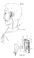
- An individual 2 (fig. 1, 2) is provided with an implant 3 for stimulating nerves (and/or muscle fibres) as is shown by curved broken lines 4.
- the implant 3 is supplied with energy and information by a transmitting member 6 provided behind the ear flap or oracle 5, said transmitting member fed by a signal processor 7 which processes sound received by a (not shown) microphone.
- the implant 3 (fig. 2) is provided with electronic components 8, 9, 10, 11 resp. and a coil or antenna 12. Electrical connections 13 of platinum or platinum iridium are used for supplying the required signals to an electrode. Arrows E show the radiated electro-magnetic energy, in which sound information is encoded.
- a package 14 of the implant 3 consists of e.g. two casing parts 15 and 16 of biocompatible glass, e.g. Borosilicate or lime glass of the Hermetronics Company from Slough in England.
- the parts 15 and 16 are sealed in a biocompatible way, e.g. by means of adhesive, laser welding, resist welding, ultrasonic welding or hot cap sealing. Conducts of the connections 13 through the package 14 are sintered.
- helium gas can be inserted, such that by means of a helium sniffer the seal can be checked on hermeticity. It is also possible not to bring this package into an atmosphere consisting of helium or another gas during some time period and afterwards to check for hermeticity outside this atmosphere (see e.g. Vakuumtechnik, Rudolf A. Lang Verlag, 627 Idstein, 23 (1974) volume 3, pages 77-80). A hermeticity of 10 ⁇ 6 Pa.l/s (10 ⁇ 8 mbar.l/s) can easily be achieved; this is sufficient for implantation in the human or other living body.
- an ear piece 20 which has the traditional shape to fit easily behind the ear 21 of a subject is provided with a lead 22 for connection at 23 to a rod shaped ear piece or mold 24, e.g. of plastic material and formed such as to be inserted into the auditory duct of the subject.
- This ear mold 24 inludes a (not shown) coil or inductor to be coupled with an inductor 26 to be implanted around the auditory duct 25.
- this conductor or coil 26 - diameter and height e.g. 2 mm, diameter of the windings e.g. 0,7 mm -is conical, such as to fit around the inwardly tapering duct 25.
- the coil 26 is flexible by means of a layer of silicon around the windings, such as to prevent painful contact after implantation between ear piece 24 and coil 26.
- Conductor or coil 26 is connected by means of line 27 to implant 28 which consists of a housing 29 of titanium provided with a window 38 of glass or transparant plastic or ceramic material.
- the ear piece 20 is provided with a microphone 30. Electrical signals supplied by this microphone are fed through line 31 to a not shown speech processor (see e.g. fig. 2).
- This speech processor encodes information as required by the implant. This information is fed from the ear piece 20 opposite to the window 38 by means of a not shown infrared radiation emitting element 39 to the implant.
- This infrared radiation emitting element 39 is contacted directly to the skin.
- the required power for the IR-detector is only a few ⁇ Watt so that the emitting element 39 will emit e.g. a few ⁇ Watt of power, but more emitting power will be possible without damaging the animate tissue.
- the IR-transmitter and IR-detector are aligned in a natural way by means of the ear and traditionally shaped ear piece and mold; there is no significant anatomical spread in different ear locations. Also the implant can easily be secured to the skull 33 of the subject. Pulses can be transmitted at the high rate, pulses having a width of less than 400 nsec are achievable.
- a lead 34 to an electrode 35 which is to be implanted in the cochlea of the deaf subject.
- the electrode 35 has branches (not shown) for stimulating different locations within the cochlea.
- the electrode is flexible and provided with a hook shaped end part (not shown) such as to be easily implantable into the cochlea by a surgeon. Stimulation is achieved through physiological fluid and nerve fibres 36.
- an antenna 37 Also there is connected to the implant 28 an antenna 37, the function of which will be described hereinafter.
- Power from the lead 27 is rectified in rectifier 40 and fed to a voltage supply 41, which supplies voltage to all the different functional blocks within broken line 42, as is indicated by arrows A.
- the functions within broken line 42 are included in a custom integrated circuit especially designed for the system of the present invention.
- the infrared radiation is detected by detector 43 and fed to input monitor 44; in case the puls shape is not correct -e.g. if a spike occurs -, a signal is fed to reset 45 which resets the integrated circuit and prevents a stimulating current within the cochlea.
- a pulse accepted by the input monitor will be fed to a pulse sequence detection unit 46 which detects time intervals between pulses, as hereinafter will be more fully described.
- the first pulse determines at 46 the mode in which the system will operate
- the second pulse determines at 48 which of eight channels 51-58 of the electrode 35 will be activated, while at 49 the magnitude or quantity of the chosen channel is determined.
- the shape of the stimulating pulse is chosen by mode unit 47.
- Mode measuring is also chosen by mode unit 47 at 61. In the measuring mode a signal is provided by output 62 to the antenna 37.
- Clock 32 provides clock signals for the circuit; the clock rate can be set before implantation between 250nsec- 2 ⁇ sec. The clock is synchronized at receiving each next accepted pulse.
- Fig. 5 shows an example of a pulse sequence to be transmitted by the ear piece and to be received by the IR-detector 43 (fig. 4).
- T0 is the period of one cycle of the clock 63 while P s designates the synchronizing pulse having a width of 4 x T0;
- T1 selects the mode (in this case biphasic see fig.
- T1 is between 2 x T0 and 4 x T0
- P m stands for mode selection pulse and a duration of 2 x T0
- T2 defines the channel to be activated, in this case channel 2, which means that T2 is in between 4 x T0 and 6 x T0
- P ch stands for channel selection pulse and has a duration of 2 x T0
- T3 defines the strenght of the stimulating pulse at channel 2, in this case e.g. 1,5 mA
- P cs has a width of 2 x T0.
- Fig. 6 shows a biphasic pulse with a duration ⁇ and extending between V max and ⁇ V max in which ⁇ can be set before implantation and V max is determined by T3.
- the biphasic pulse is symmetric around the zero-axis, such that no charge will build up in the cochlea of the subject.
- the inverse of fig. 6 is called biphasic negative, in which the first edge of the pulse is going negative and the last edge is going downwardly.
- Other modes in which the system of the present invention can operate are so called normal modes (positive and negative) in which a constant current is supplied to two electrode branches, in which negative or positive decides which way the current will have to flow.
- a measuring signal to the antenna, giving an indication of the supply voltage at 41 or the measured voltage at a selected electrode.
- the signals have e.g. a frequency of 1 MHz and can be detected outside the subject, such that the surveillance of correct operation of the implant can be established.
- T1, T2 and T3 have a relatively large value, the relative spread in those values is approximately held constant, such that the allowed absolute spread in values to be detected is increased.
- the clock is only activated when the input monitor detects a synchronization pulse.
- Reset unit 45 provides in resetting the circuit of fig. 4 at missing one pulse, at erroneous detection of the synchronizing pulse, detection of decreasing power supply, and spikes occurring in the information supply. Therefore the described coding provides a very safe stimulating system, without inducing damaging current in an anminate body.
- the shown preferred embodiment for stimulating auditory nerves of a subject has external parts outside the animate body to be easily removed at e.g. swimming. It is expected that with this system a person having a good function of the auditory nerves will be able to comprehend speech.
- the system of the present invention uses coding in time sequence and the signal processing within the implant has a pipeline structure - not an operation according to the Von Neumann principle - a high rate of information transfer is achieved.
- IR-pulses can be made smaller than 400 nsec.
- the implant is again synchronized and reset.
- the shown embodiments show systems for stimulating nerves, but the present invention can also be used for stimulating muscles, e.g. hard muscles. The scope of protection is defined by the following claims.
Landscapes
- Health & Medical Sciences (AREA)
- Otolaryngology (AREA)
- Engineering & Computer Science (AREA)
- Biomedical Technology (AREA)
- Life Sciences & Earth Sciences (AREA)
- Public Health (AREA)
- Veterinary Medicine (AREA)
- Animal Behavior & Ethology (AREA)
- General Health & Medical Sciences (AREA)
- Radiology & Medical Imaging (AREA)
- Psychology (AREA)
- Neurology (AREA)
- Physiology (AREA)
- Physics & Mathematics (AREA)
- Acoustics & Sound (AREA)
- Biophysics (AREA)
- Nuclear Medicine, Radiotherapy & Molecular Imaging (AREA)
- Heart & Thoracic Surgery (AREA)
- Vascular Medicine (AREA)
- Prostheses (AREA)
- Medicines That Contain Protein Lipid Enzymes And Other Medicines (AREA)
- Electrotherapy Devices (AREA)
- Pharmaceuticals Containing Other Organic And Inorganic Compounds (AREA)
Claims (14)
- Système de stimulation d'au moins un nerf et/ou d'une fibre musculaire chez un sujet vivant, comprenant une unité de réception destinée à être implantée dans le sujet et une unité de transmission à monter hors du corps du sujet, dans lequel des informations sont transmises au moyen d'ondes électromagnétiques de l'unité de transmission à l'unité de réception pour induire des signaux électriques de stimulation dans la fibre, dans lequel l'unité de réception comprend des moyens d'alimentation (41) destinés à alimenter en courant, reçu au moyen d'ondes électromagnétique transmises au moyen d'inducteurs primaire (24) et secondaire (26) pouvant coopérer, un circuit afin de donner le signal électrique de stimulation, caractérisé en ce que l'inducteur primaire (24) est destiné à être introduit dans le conduit auditif du sujet et fait partie de l'unité de transmission et en ce que l'inducteur secondaire (26) ou la bobine est destinée à être implantée autour du conduit auditif du sujet et fait partie de l'unité de réception.
- Système de stimulation selon la revendication 1, pourvu, du côté de la réception, d'un détecteur (38) destiné à détecter la radiation infra-rouge devant être transmise par l'unité de transmission, qui doit être placée en contact avec ou à faible distance de la peau du sujet.
- Système de stimulation selon la revendication 1 ou 2, caractérisé en ce que l'information à transmettre est codée en séquence dans le temps.
- Système de stimulation selon la revendication 1, 2 ou 3, caractérisé en ce que les informations à transmettre sont traitées de façon chevauchée.
- Système de stimulation selon l'une quelconque des revendications précédentes, caractérisé en ce que l'implant est pourvu d'une antenne (37) servant à retransmettre les informations hors du corps du patient.
- Système de stimulation selon l'une quelconque des revendications précédentes, caractérisé en ce que l'unité de réception est logée dans un boîtier (14, 29) constitué, au moins partiellement, par un matériau biocompatible.
- Système de stimulation selon la revendication 6, caractérisé en ce que le matériau est du verre.
- Système de stimulation selon la revendication 6 ou 7, caractérisé en ce que le boîtier (29) est constitué d'au moins deux parties préformées en titane, dont l'une est pourvue d'une fenêtre (38) transparente en verre.
- Système de stimulation selon la revendication 7, caractérisé en ce que le boîtier (14) est constitué en totalité par du verre biocompatible.
- Système de stimulation selon l'une quelconque des revendications 6-9, caractérisé en ce que le boîtier est scellé hermétiquement.
- Système de stimulation selon l'une quelconque des revendications 1-5, pourvu d'un boîtier constitué, au moins partiellement, par du matériau céramique.
- Système de stimulation selon l'une quelconque des revendications précédentes, caractérisé en ce que l'unité de réception est pourvue d'au moins une unité intégrée.
- Système de stimulation selon l'une quelconque des revendications précédentes, pourvu d'une électrode (35) destinée à être insérée dans le limaçon osseux d'un sujet et comprenant une partie terminale en forme de crochet.
- Système de stimulation selon l'une quelconque des revendications précédentes, caractérisé en ce que la bobine (26) destinée à être implantée autour d'un conduit auditif est pourvue d'enroulements présentant un revêtement souple, par exemple en silicone.
Priority Applications (2)
| Application Number | Priority Date | Filing Date | Title |
|---|---|---|---|
| AT87201505T ATE96294T1 (de) | 1986-08-08 | 1987-08-06 | System zum stimulieren wenigstens eines nervs und/oder einer muskelfaser. |
| JP63044051A JPS6443252A (en) | 1987-08-06 | 1988-02-25 | Stimulation system, housing, embedding, data processing circuit, ear pad ear model, electrode and coil |
Applications Claiming Priority (2)
| Application Number | Priority Date | Filing Date | Title |
|---|---|---|---|
| NL8602043 | 1986-08-08 | ||
| NL8602043A NL8602043A (nl) | 1986-08-08 | 1986-08-08 | Werkwijze voor het verpakken van een implantaat, bijvoorbeeld een electronisch circuit, verpakking en implantaat. |
Publications (3)
| Publication Number | Publication Date |
|---|---|
| EP0259906A2 EP0259906A2 (fr) | 1988-03-16 |
| EP0259906A3 EP0259906A3 (en) | 1989-07-19 |
| EP0259906B1 true EP0259906B1 (fr) | 1993-10-27 |
Family
ID=19848391
Family Applications (1)
| Application Number | Title | Priority Date | Filing Date |
|---|---|---|---|
| EP87201505A Expired - Lifetime EP0259906B1 (fr) | 1986-08-08 | 1987-08-06 | Système de stimulation d'au moins un nerf et/ou fibre d'un muscle |
Country Status (5)
| Country | Link |
|---|---|
| US (1) | US4932405A (fr) |
| EP (1) | EP0259906B1 (fr) |
| AT (1) | ATE96294T1 (fr) |
| DE (1) | DE3787944T2 (fr) |
| NL (1) | NL8602043A (fr) |
Families Citing this family (85)
| Publication number | Priority date | Publication date | Assignee | Title |
|---|---|---|---|---|
| JPH02500814A (ja) * | 1987-07-24 | 1990-03-22 | コクリア・プロプライエタリー・リミテッド | 蝸牛電極組立体を挿入する装置及び方法 |
| CA1331803C (fr) * | 1988-12-21 | 1994-08-30 | Murray A. Davis | Prothese auditive |
| ATE110252T1 (de) * | 1989-06-07 | 1994-09-15 | Assistance Publique | Transkutane verbindungseinrichtung. |
| US5603726A (en) * | 1989-09-22 | 1997-02-18 | Alfred E. Mann Foundation For Scientific Research | Multichannel cochlear implant system including wearable speech processor |
| US5876425A (en) * | 1989-09-22 | 1999-03-02 | Advanced Bionics Corporation | Power control loop for implantable tissue stimulator |
| US5531774A (en) * | 1989-09-22 | 1996-07-02 | Alfred E. Mann Foundation For Scientific Research | Multichannel implantable cochlear stimulator having programmable bipolar, monopolar or multipolar electrode configurations |
| US5314458A (en) * | 1990-06-01 | 1994-05-24 | University Of Michigan | Single channel microstimulator |
| WO1992017991A1 (fr) * | 1991-04-01 | 1992-10-15 | Resound Corporation | Procede de communication discrete a commande electromagnetique a distance |
| US5425752A (en) * | 1991-11-25 | 1995-06-20 | Vu'nguyen; Dung D. | Method of direct electrical myostimulation using acupuncture needles |
| US5476494A (en) * | 1992-09-11 | 1995-12-19 | Massachusetts Institute Of Technology | Low pressure neural contact structure |
| US5531787A (en) * | 1993-01-25 | 1996-07-02 | Lesinski; S. George | Implantable auditory system with micromachined microsensor and microactuator |
| US5697975A (en) | 1994-02-09 | 1997-12-16 | The University Of Iowa Research Foundation | Human cerebral cortex neural prosthetic for tinnitus |
| US5800535A (en) * | 1994-02-09 | 1998-09-01 | The University Of Iowa Research Foundation | Wireless prosthetic electrode for the brain |
| US5496369A (en) * | 1994-02-09 | 1996-03-05 | University Of Iowa Research Foundation | Human cerebral cortex neural prosthetic |
| AU1837695A (en) * | 1994-02-09 | 1995-08-29 | University Of Iowa Research Foundation, The | Human cerebral cortex neural prosthetic |
| US7077822B1 (en) | 1994-02-09 | 2006-07-18 | The University Of Iowa Research Foundation | Stereotactic hypothalamic obesity probe |
| US6129685A (en) * | 1994-02-09 | 2000-10-10 | The University Of Iowa Research Foundation | Stereotactic hypothalamic obesity probe |
| US5797854A (en) * | 1995-08-01 | 1998-08-25 | Hedgecock; James L. | Method and apparatus for testing and measuring current perception threshold and motor nerve junction performance |
| US5772575A (en) * | 1995-09-22 | 1998-06-30 | S. George Lesinski | Implantable hearing aid |
| US5951601A (en) * | 1996-03-25 | 1999-09-14 | Lesinski; S. George | Attaching an implantable hearing aid microactuator |
| JP3801212B2 (ja) * | 1996-05-24 | 2006-07-26 | エス ジョージ レジンスキー | 埋込み可能な補聴器用改良マイクロフォン |
| EP0912146B1 (fr) * | 1996-07-19 | 2009-11-18 | Armand P. Neukermans | Microactionneur biocompatible et implantable pour prothese auditive |
| AU5478298A (en) | 1997-01-13 | 1998-08-03 | Neurodan A/S | An implantable nerve stimulator electrode |
| US5991664A (en) * | 1997-03-09 | 1999-11-23 | Cochlear Limited | Compact inductive arrangement for medical implant data and power transfer |
| USD419677S (en) * | 1997-11-04 | 2000-01-25 | Med-El Elektromedizinische Gerate Ges.M.B.H. | Speech processor for use with a cochlear implant |
| US6907130B1 (en) * | 1998-02-13 | 2005-06-14 | University Of Iowa Research Foundation | Speech processing system and method using pseudospontaneous stimulation |
| JP2002524124A (ja) * | 1998-09-04 | 2002-08-06 | ウルフ リサーチ プロプライエタリー リミテッド | 医療埋込みシステム |
| US6516227B1 (en) | 1999-07-27 | 2003-02-04 | Advanced Bionics Corporation | Rechargeable spinal cord stimulator system |
| DE10015421C2 (de) * | 2000-03-28 | 2002-07-04 | Implex Ag Hearing Technology I | Teil- oder vollimplantierbares Hörsystem |
| AU2001268142B2 (en) * | 2000-06-01 | 2006-05-18 | Otologics, Llc | Method and apparatus for measuring the performance of an implantable middle ear hearing aid, and the response of patient wearing such a hearing aid |
| US6707920B2 (en) | 2000-12-12 | 2004-03-16 | Otologics Llc | Implantable hearing aid microphone |
| US8147544B2 (en) * | 2001-10-30 | 2012-04-03 | Otokinetics Inc. | Therapeutic appliance for cochlea |
| US7529587B2 (en) | 2003-10-13 | 2009-05-05 | Cochlear Limited | External speech processor unit for an auditory prosthesis |
| US7204799B2 (en) * | 2003-11-07 | 2007-04-17 | Otologics, Llc | Microphone optimized for implant use |
| US7556597B2 (en) * | 2003-11-07 | 2009-07-07 | Otologics, Llc | Active vibration attenuation for implantable microphone |
| US20050137652A1 (en) * | 2003-12-19 | 2005-06-23 | The Board of Regents of the University of Texas at Dallas | System and method for interfacing cellular matter with a machine |
| US20090198293A1 (en) * | 2003-12-19 | 2009-08-06 | Lawrence Cauller | Microtransponder Array for Implant |
| US7214179B2 (en) * | 2004-04-01 | 2007-05-08 | Otologics, Llc | Low acceleration sensitivity microphone |
| US7840020B1 (en) | 2004-04-01 | 2010-11-23 | Otologics, Llc | Low acceleration sensitivity microphone |
| US7867160B2 (en) | 2004-10-12 | 2011-01-11 | Earlens Corporation | Systems and methods for photo-mechanical hearing transduction |
| US8295523B2 (en) | 2007-10-04 | 2012-10-23 | SoundBeam LLC | Energy delivery and microphone placement methods for improved comfort in an open canal hearing aid |
| US7668325B2 (en) * | 2005-05-03 | 2010-02-23 | Earlens Corporation | Hearing system having an open chamber for housing components and reducing the occlusion effect |
| US8096937B2 (en) | 2005-01-11 | 2012-01-17 | Otologics, Llc | Adaptive cancellation system for implantable hearing instruments |
| US7775964B2 (en) * | 2005-01-11 | 2010-08-17 | Otologics Llc | Active vibration attenuation for implantable microphone |
| US7582052B2 (en) * | 2005-04-27 | 2009-09-01 | Otologics, Llc | Implantable hearing aid actuator positioning |
| US7489793B2 (en) * | 2005-07-08 | 2009-02-10 | Otologics, Llc | Implantable microphone with shaped chamber |
| US7522738B2 (en) * | 2005-11-30 | 2009-04-21 | Otologics, Llc | Dual feedback control system for implantable hearing instrument |
| WO2008137703A1 (fr) * | 2007-05-04 | 2008-11-13 | Arizona Board Of Regents For And On Behalf Of Arizona State University | Systèmes et procédés pour une transmission sans fil de biopotentiels |
| US7630771B2 (en) * | 2007-06-25 | 2009-12-08 | Microtransponder, Inc. | Grooved electrode and wireless microtransponder system |
| WO2009049320A1 (fr) | 2007-10-12 | 2009-04-16 | Earlens Corporation | Système et procédé multifonction pour une audition et une communication intégrées avec gestion de l'annulation du bruit et de la contre-réaction |
| US8472654B2 (en) | 2007-10-30 | 2013-06-25 | Cochlear Limited | Observer-based cancellation system for implantable hearing instruments |
| US20090157145A1 (en) * | 2007-11-26 | 2009-06-18 | Lawrence Cauller | Transfer Coil Architecture |
| US8457757B2 (en) | 2007-11-26 | 2013-06-04 | Micro Transponder, Inc. | Implantable transponder systems and methods |
| AU2008329642A1 (en) * | 2007-11-26 | 2009-06-04 | Microtransponder Inc. | Implantable driver with charge balancing |
| US9089707B2 (en) * | 2008-07-02 | 2015-07-28 | The Board Of Regents, The University Of Texas System | Systems, methods and devices for paired plasticity |
| KR100977525B1 (ko) * | 2008-04-11 | 2010-08-23 | 주식회사 뉴로바이오시스 | 적외선 통신 방식의 귓속형 인공 와우 장치 |
| WO2009155361A1 (fr) | 2008-06-17 | 2009-12-23 | Earlens Corporation | Dispositifs auditifs électro-mécaniques optiques présentant une architecture combinant puissance et signal |
| US8396239B2 (en) | 2008-06-17 | 2013-03-12 | Earlens Corporation | Optical electro-mechanical hearing devices with combined power and signal architectures |
| WO2009155358A1 (fr) | 2008-06-17 | 2009-12-23 | Earlens Corporation | Dispositifs d’audition électromécaniques optiques dotés de composants d’alimentation et de signal séparés |
| DK3509324T3 (da) | 2008-09-22 | 2023-10-02 | Earlens Corp | Balancerede armaturindretninger og fremgangsmåder til at høre |
| US8771166B2 (en) | 2009-05-29 | 2014-07-08 | Cochlear Limited | Implantable auditory stimulation system and method with offset implanted microphones |
| DK2438768T3 (en) | 2009-06-05 | 2016-06-06 | Earlens Corp | Optically coupled acoustically mellemøreimplantatindretning |
| US9544700B2 (en) | 2009-06-15 | 2017-01-10 | Earlens Corporation | Optically coupled active ossicular replacement prosthesis |
| CN102640435B (zh) | 2009-06-18 | 2016-11-16 | 伊尔莱茵斯公司 | 光学耦合的耳蜗植入系统及方法 |
| US8401214B2 (en) | 2009-06-18 | 2013-03-19 | Earlens Corporation | Eardrum implantable devices for hearing systems and methods |
| WO2011005479A2 (fr) | 2009-06-22 | 2011-01-13 | SoundBeam LLC | Systèmes et procédés de conduction osseuse à couplage optique |
| CN102598714A (zh) | 2009-06-22 | 2012-07-18 | 音束有限责任公司 | 圆窗耦合的听力系统和方法 |
| WO2010151636A2 (fr) | 2009-06-24 | 2010-12-29 | SoundBeam LLC | Dispositifs et procédés de stimulation cochléaire optique |
| US8715154B2 (en) | 2009-06-24 | 2014-05-06 | Earlens Corporation | Optically coupled cochlear actuator systems and methods |
| EP2506922B1 (fr) * | 2009-12-01 | 2016-08-24 | MED-EL Elektromedizinische Geräte GmbH | Signal inductif et transfert d'énergie à travers le canal auditif externe |
| WO2012088187A2 (fr) | 2010-12-20 | 2012-06-28 | SoundBeam LLC | Appareil auditif intra-auriculaire anatomiquement personnalisé |
| US10034103B2 (en) | 2014-03-18 | 2018-07-24 | Earlens Corporation | High fidelity and reduced feedback contact hearing apparatus and methods |
| US20150343225A1 (en) | 2014-06-02 | 2015-12-03 | Charles Roger Aaron Leigh | Distributed Implantable Hearing Systems |
| EP3169396B1 (fr) | 2014-07-14 | 2021-04-21 | Earlens Corporation | Limitation de crête et polarisation coulissante pour dispositifs auditifs optiques |
| US9924276B2 (en) | 2014-11-26 | 2018-03-20 | Earlens Corporation | Adjustable venting for hearing instruments |
| US10284968B2 (en) | 2015-05-21 | 2019-05-07 | Cochlear Limited | Advanced management of an implantable sound management system |
| EP3355801B1 (fr) | 2015-10-02 | 2021-05-19 | Earlens Corporation | Appareil intra-auriculaire personnalisé d'administration de médicament |
| US11350226B2 (en) | 2015-12-30 | 2022-05-31 | Earlens Corporation | Charging protocol for rechargeable hearing systems |
| US10306381B2 (en) | 2015-12-30 | 2019-05-28 | Earlens Corporation | Charging protocol for rechargable hearing systems |
| US10492010B2 (en) | 2015-12-30 | 2019-11-26 | Earlens Corporations | Damping in contact hearing systems |
| US11071869B2 (en) | 2016-02-24 | 2021-07-27 | Cochlear Limited | Implantable device having removable portion |
| US20180077504A1 (en) | 2016-09-09 | 2018-03-15 | Earlens Corporation | Contact hearing systems, apparatus and methods |
| WO2018093733A1 (fr) | 2016-11-15 | 2018-05-24 | Earlens Corporation | Procédure d'impression améliorée |
| WO2019173470A1 (fr) | 2018-03-07 | 2019-09-12 | Earlens Corporation | Dispositif auditif de contact et matériaux de structure de rétention |
| WO2019199680A1 (fr) | 2018-04-09 | 2019-10-17 | Earlens Corporation | Filtre dynamique |
Family Cites Families (20)
| Publication number | Priority date | Publication date | Assignee | Title |
|---|---|---|---|---|
| US26809A (en) * | 1860-01-10 | Henry belfield | ||
| USRE26809E (en) | 1966-10-20 | 1970-03-03 | Implantable electrode | |
| US3672352A (en) * | 1969-04-09 | 1972-06-27 | George D Summers | Implantable bio-data monitoring method and apparatus |
| US3945387A (en) * | 1974-09-09 | 1976-03-23 | General Electric Company | Implantable cardiac pacer with characteristic controllable circuit and control device therefor |
| US4301814A (en) * | 1977-04-26 | 1981-11-24 | Meer Sneer | Cassette implant |
| US4314562A (en) * | 1977-05-04 | 1982-02-09 | Medtronic, Inc. | Enclosure system for body implantable electrical systems |
| DE2750164A1 (de) * | 1977-11-09 | 1979-05-10 | Michael S Dipl Ing Lampadius | Herzschrittmacher |
| US4142532A (en) * | 1978-04-07 | 1979-03-06 | Medtronic, Inc. | Body implantable stimulator with novel connector and method |
| DE2823798C2 (de) * | 1978-05-31 | 1980-07-03 | Siemens Ag, 1000 Berlin Und 8000 Muenchen | Verfahren zur elektrischen Stimulation des Hörnervs und Multikanal-Hörprothese zur Durchführung des Verfahrens |
| US4677982A (en) * | 1981-12-31 | 1987-07-07 | New York University | Infrared transcutaneous communicator and method of using same |
| US4516820A (en) * | 1983-01-27 | 1985-05-14 | The Commonwealth Of Australia | Cochlear prosthesis package connector |
| US4532930A (en) * | 1983-04-11 | 1985-08-06 | Commonwealth Of Australia, Dept. Of Science & Technology | Cochlear implant system for an auditory prosthesis |
| US4545381A (en) * | 1984-10-01 | 1985-10-08 | Cordis Corporation | Adapter for converting a metal encapsulated implantable cardiac pacer to an externally worn cardiac pacer |
| CA1246680A (fr) * | 1984-10-22 | 1988-12-13 | James M. Harrison | Transfert d'energie pour prothese implantee |
| DE3506721A1 (de) * | 1985-02-26 | 1986-08-28 | Hortmann GmbH, 7449 Neckartenzlingen | Uebertragungssystem fuer implantierte hoerprothesen |
| US4592359A (en) * | 1985-04-02 | 1986-06-03 | The Board Of Trustees Of The Leland Stanford Junior University | Multi-channel implantable neural stimulator |
| US4606329A (en) * | 1985-05-22 | 1986-08-19 | Xomed, Inc. | Implantable electromagnetic middle-ear bone-conduction hearing aid device |
| US4612915A (en) * | 1985-05-23 | 1986-09-23 | Xomed, Inc. | Direct bone conduction hearing aid device |
| US4741340A (en) * | 1985-12-18 | 1988-05-03 | Cordis Corporation | Pulse to sinewave telemetry system |
| DD252319A1 (de) * | 1986-08-04 | 1987-12-16 | Zentralinstitut Fuer Diabetes | Implantierbare infusionspumpe |
-
1986
- 1986-08-08 NL NL8602043A patent/NL8602043A/nl not_active Application Discontinuation
-
1987
- 1987-08-06 AT AT87201505T patent/ATE96294T1/de active
- 1987-08-06 EP EP87201505A patent/EP0259906B1/fr not_active Expired - Lifetime
- 1987-08-06 DE DE87201505T patent/DE3787944T2/de not_active Expired - Fee Related
- 1987-08-07 US US07/082,548 patent/US4932405A/en not_active Expired - Fee Related
Also Published As
| Publication number | Publication date |
|---|---|
| DE3787944T2 (de) | 1994-02-17 |
| EP0259906A2 (fr) | 1988-03-16 |
| US4932405A (en) | 1990-06-12 |
| DE3787944D1 (de) | 1993-12-02 |
| ATE96294T1 (de) | 1993-11-15 |
| NL8602043A (nl) | 1988-03-01 |
| EP0259906A3 (en) | 1989-07-19 |
Similar Documents
| Publication | Publication Date | Title |
|---|---|---|
| EP0259906B1 (fr) | Système de stimulation d'au moins un nerf et/ou fibre d'un muscle | |
| US5749912A (en) | Low-cost, four-channel cochlear implant | |
| EP2274923B1 (fr) | Système d'implant cochléaire dans l'oreille (ite) à l'aide d'une communication de données par infrarouge | |
| US7346397B2 (en) | Cochlear implant | |
| US6648914B2 (en) | Totally implantable cochlear prosthesis | |
| US5571148A (en) | Implantable multichannel stimulator | |
| EP2296750B1 (fr) | Capteur de son implantable pour prothèses auditives | |
| US8478416B2 (en) | Implant power control | |
| US5941905A (en) | Public alarm for cochlear implant | |
| JPS621726B2 (fr) | ||
| WO2003092326A1 (fr) | Implant cochleaire compatible irm | |
| EP2498874B1 (fr) | Système d'alimentation d'implant | |
| US7873420B2 (en) | Password protection for cochlear implant | |
| US11904167B2 (en) | Auxiliary device connection | |
| EP1084593B1 (fr) | Appareil et procede d'alarme publique pour implants cochleaires | |
| US20060178720A1 (en) | Method and apparatus for sealing a lumen in an electrode assembly | |
| AU2007202342A1 (en) | Cochlear implant | |
| AU2001268821B2 (en) | Cochlear implant | |
| AU2001268821A1 (en) | Cochlear implant | |
| AU2003287772A1 (en) | Method and apparatus for sealing a lumen in an electrode assembly |
Legal Events
| Date | Code | Title | Description |
|---|---|---|---|
| PUAI | Public reference made under article 153(3) epc to a published international application that has entered the european phase |
Free format text: ORIGINAL CODE: 0009012 |
|
| AK | Designated contracting states |
Kind code of ref document: A2 Designated state(s): AT BE CH DE ES FR GB GR IT LI LU NL SE |
|
| PUAL | Search report despatched |
Free format text: ORIGINAL CODE: 0009013 |
|
| AK | Designated contracting states |
Kind code of ref document: A3 Designated state(s): AT BE CH DE ES FR GB GR IT LI LU NL SE |
|
| 17P | Request for examination filed |
Effective date: 19891019 |
|
| 17Q | First examination report despatched |
Effective date: 19910208 |
|
| GRAA | (expected) grant |
Free format text: ORIGINAL CODE: 0009210 |
|
| AK | Designated contracting states |
Kind code of ref document: B1 Designated state(s): AT BE CH DE ES FR GB GR IT LI LU NL SE |
|
| PG25 | Lapsed in a contracting state [announced via postgrant information from national office to epo] |
Ref country code: SE Effective date: 19931027 Ref country code: IT Free format text: LAPSE BECAUSE OF FAILURE TO SUBMIT A TRANSLATION OF THE DESCRIPTION OR TO PAY THE FEE WITHIN THE PRE;WARNING: LAPSES OF ITALIAN PATENTS WITH EFFECTIVE DATE BEFORE 2007 MAY HAVE OCCURRED AT ANY TIME BEFORE 2007. THE CORRECT EFFECTIVE DATE MAY BE DIFFERENT FROM THE ONE RECORDED.SCRIBED TIME-LIMIT Effective date: 19931027 Ref country code: NL Effective date: 19931027 Ref country code: BE Effective date: 19931027 Ref country code: CH Effective date: 19931027 Ref country code: GR Free format text: LAPSE BECAUSE OF FAILURE TO SUBMIT A TRANSLATION OF THE DESCRIPTION OR TO PAY THE FEE WITHIN THE PRESCRIBED TIME-LIMIT Effective date: 19931027 Ref country code: AT Effective date: 19931027 Ref country code: LI Effective date: 19931027 |
|
| REF | Corresponds to: |
Ref document number: 96294 Country of ref document: AT Date of ref document: 19931115 Kind code of ref document: T |
|
| REF | Corresponds to: |
Ref document number: 3787944 Country of ref document: DE Date of ref document: 19931202 |
|
| ET | Fr: translation filed | ||
| REG | Reference to a national code |
Ref country code: CH Ref legal event code: PL |
|
| PG25 | Lapsed in a contracting state [announced via postgrant information from national office to epo] |
Ref country code: ES Free format text: LAPSE BECAUSE OF FAILURE TO SUBMIT A TRANSLATION OF THE DESCRIPTION OR TO PAY THE FEE WITHIN THE PRESCRIBED TIME-LIMIT Effective date: 19940207 |
|
| NLV1 | Nl: lapsed or annulled due to failure to fulfill the requirements of art. 29p and 29m of the patents act | ||
| PGFP | Annual fee paid to national office [announced via postgrant information from national office to epo] |
Ref country code: GB Payment date: 19940725 Year of fee payment: 8 |
|
| PLBE | No opposition filed within time limit |
Free format text: ORIGINAL CODE: 0009261 |
|
| STAA | Information on the status of an ep patent application or granted ep patent |
Free format text: STATUS: NO OPPOSITION FILED WITHIN TIME LIMIT |
|
| PG25 | Lapsed in a contracting state [announced via postgrant information from national office to epo] |
Ref country code: LU Free format text: LAPSE BECAUSE OF NON-PAYMENT OF DUE FEES Effective date: 19940831 |
|
| PGFP | Annual fee paid to national office [announced via postgrant information from national office to epo] |
Ref country code: FR Payment date: 19940831 Year of fee payment: 8 |
|
| PGFP | Annual fee paid to national office [announced via postgrant information from national office to epo] |
Ref country code: DE Payment date: 19940930 Year of fee payment: 8 |
|
| 26N | No opposition filed | ||
| PG25 | Lapsed in a contracting state [announced via postgrant information from national office to epo] |
Ref country code: GB Effective date: 19950806 |
|
| GBPC | Gb: european patent ceased through non-payment of renewal fee |
Effective date: 19950806 |
|
| PG25 | Lapsed in a contracting state [announced via postgrant information from national office to epo] |
Ref country code: FR Effective date: 19960430 |
|
| PG25 | Lapsed in a contracting state [announced via postgrant information from national office to epo] |
Ref country code: DE Effective date: 19960501 |
|
| REG | Reference to a national code |
Ref country code: FR Ref legal event code: ST |