EP0259938A1 - Drosselapparat, Verfahren für den Gebrauch des Drosselapparats und auch Apparat für die Anwendung des Verfahrens - Google Patents
Drosselapparat, Verfahren für den Gebrauch des Drosselapparats und auch Apparat für die Anwendung des Verfahrens Download PDFInfo
- Publication number
- EP0259938A1 EP0259938A1 EP19870201735 EP87201735A EP0259938A1 EP 0259938 A1 EP0259938 A1 EP 0259938A1 EP 19870201735 EP19870201735 EP 19870201735 EP 87201735 A EP87201735 A EP 87201735A EP 0259938 A1 EP0259938 A1 EP 0259938A1
- Authority
- EP
- European Patent Office
- Prior art keywords
- slit
- pressure
- flow
- throttling device
- orifice
- Prior art date
- Legal status (The legal status is an assumption and is not a legal conclusion. Google has not performed a legal analysis and makes no representation as to the accuracy of the status listed.)
- Granted
Links
- 238000000034 method Methods 0.000 title claims abstract description 24
- 239000007788 liquid Substances 0.000 claims abstract description 45
- 230000008569 process Effects 0.000 claims abstract description 13
- 238000005188 flotation Methods 0.000 claims description 7
- 230000003993 interaction Effects 0.000 claims description 5
- 238000000746 purification Methods 0.000 claims description 5
- 229920006395 saturated elastomer Polymers 0.000 claims description 3
- 238000000926 separation method Methods 0.000 claims description 3
- 239000006185 dispersion Substances 0.000 claims description 2
- 230000005484 gravity Effects 0.000 claims description 2
- 239000003595 mist Substances 0.000 abstract description 11
- XLYOFNOQVPJJNP-UHFFFAOYSA-N water Substances O XLYOFNOQVPJJNP-UHFFFAOYSA-N 0.000 description 23
- 230000015572 biosynthetic process Effects 0.000 description 5
- 239000002245 particle Substances 0.000 description 5
- 238000011109 contamination Methods 0.000 description 4
- 230000009471 action Effects 0.000 description 3
- 235000012206 bottled water Nutrition 0.000 description 2
- 230000008859 change Effects 0.000 description 2
- 230000007423 decrease Effects 0.000 description 2
- 239000003651 drinking water Substances 0.000 description 2
- 239000002351 wastewater Substances 0.000 description 2
- 230000001154 acute effect Effects 0.000 description 1
- 230000009286 beneficial effect Effects 0.000 description 1
- 230000008901 benefit Effects 0.000 description 1
- 238000004140 cleaning Methods 0.000 description 1
- 238000004581 coalescence Methods 0.000 description 1
- 230000001419 dependent effect Effects 0.000 description 1
- 238000009300 dissolved air flotation Methods 0.000 description 1
- 238000005516 engineering process Methods 0.000 description 1
- 239000010419 fine particle Substances 0.000 description 1
- 238000005189 flocculation Methods 0.000 description 1
- 244000144992 flock Species 0.000 description 1
- 230000007246 mechanism Effects 0.000 description 1
- 230000021715 photosynthesis, light harvesting Effects 0.000 description 1
Images

Classifications
-
- B—PERFORMING OPERATIONS; TRANSPORTING
- B03—SEPARATION OF SOLID MATERIALS USING LIQUIDS OR USING PNEUMATIC TABLES OR JIGS; MAGNETIC OR ELECTROSTATIC SEPARATION OF SOLID MATERIALS FROM SOLID MATERIALS OR FLUIDS; SEPARATION BY HIGH-VOLTAGE ELECTRIC FIELDS
- B03D—FLOTATION; DIFFERENTIAL SEDIMENTATION
- B03D1/00—Flotation
- B03D1/14—Flotation machines
- B03D1/24—Pneumatic
-
- B—PERFORMING OPERATIONS; TRANSPORTING
- B01—PHYSICAL OR CHEMICAL PROCESSES OR APPARATUS IN GENERAL
- B01F—MIXING, e.g. DISSOLVING, EMULSIFYING OR DISPERSING
- B01F25/00—Flow mixers; Mixers for falling materials, e.g. solid particles
- B01F25/30—Injector mixers
- B01F25/32—Injector mixers wherein the additional components are added in a by-pass of the main flow
-
- B—PERFORMING OPERATIONS; TRANSPORTING
- B03—SEPARATION OF SOLID MATERIALS USING LIQUIDS OR USING PNEUMATIC TABLES OR JIGS; MAGNETIC OR ELECTROSTATIC SEPARATION OF SOLID MATERIALS FROM SOLID MATERIALS OR FLUIDS; SEPARATION BY HIGH-VOLTAGE ELECTRIC FIELDS
- B03D—FLOTATION; DIFFERENTIAL SEDIMENTATION
- B03D1/00—Flotation
- B03D1/14—Flotation machines
- B03D1/1412—Flotation machines with baffles, e.g. at the wall for redirecting settling solids
-
- B—PERFORMING OPERATIONS; TRANSPORTING
- B03—SEPARATION OF SOLID MATERIALS USING LIQUIDS OR USING PNEUMATIC TABLES OR JIGS; MAGNETIC OR ELECTROSTATIC SEPARATION OF SOLID MATERIALS FROM SOLID MATERIALS OR FLUIDS; SEPARATION BY HIGH-VOLTAGE ELECTRIC FIELDS
- B03D—FLOTATION; DIFFERENTIAL SEDIMENTATION
- B03D1/00—Flotation
- B03D1/14—Flotation machines
- B03D1/1431—Dissolved air flotation machines
-
- B—PERFORMING OPERATIONS; TRANSPORTING
- B03—SEPARATION OF SOLID MATERIALS USING LIQUIDS OR USING PNEUMATIC TABLES OR JIGS; MAGNETIC OR ELECTROSTATIC SEPARATION OF SOLID MATERIALS FROM SOLID MATERIALS OR FLUIDS; SEPARATION BY HIGH-VOLTAGE ELECTRIC FIELDS
- B03D—FLOTATION; DIFFERENTIAL SEDIMENTATION
- B03D1/00—Flotation
- B03D1/14—Flotation machines
- B03D1/1493—Flotation machines with means for establishing a specified flow pattern
-
- C—CHEMISTRY; METALLURGY
- C02—TREATMENT OF WATER, WASTE WATER, SEWAGE, OR SLUDGE
- C02F—TREATMENT OF WATER, WASTE WATER, SEWAGE, OR SLUDGE
- C02F3/00—Biological treatment of water, waste water, or sewage
- C02F3/02—Aerobic processes
- C02F3/12—Activated sludge processes
- C02F3/20—Activated sludge processes using diffusers
-
- B—PERFORMING OPERATIONS; TRANSPORTING
- B01—PHYSICAL OR CHEMICAL PROCESSES OR APPARATUS IN GENERAL
- B01F—MIXING, e.g. DISSOLVING, EMULSIFYING OR DISPERSING
- B01F23/00—Mixing according to the phases to be mixed, e.g. dispersing or emulsifying
- B01F23/40—Mixing liquids with liquids; Emulsifying
-
- B—PERFORMING OPERATIONS; TRANSPORTING
- B03—SEPARATION OF SOLID MATERIALS USING LIQUIDS OR USING PNEUMATIC TABLES OR JIGS; MAGNETIC OR ELECTROSTATIC SEPARATION OF SOLID MATERIALS FROM SOLID MATERIALS OR FLUIDS; SEPARATION BY HIGH-VOLTAGE ELECTRIC FIELDS
- B03D—FLOTATION; DIFFERENTIAL SEDIMENTATION
- B03D1/00—Flotation
- B03D1/14—Flotation machines
- B03D1/1443—Feed or discharge mechanisms for flotation tanks
- B03D1/1475—Flotation tanks having means for discharging the pulp, e.g. as a bleed stream
-
- Y—GENERAL TAGGING OF NEW TECHNOLOGICAL DEVELOPMENTS; GENERAL TAGGING OF CROSS-SECTIONAL TECHNOLOGIES SPANNING OVER SEVERAL SECTIONS OF THE IPC; TECHNICAL SUBJECTS COVERED BY FORMER USPC CROSS-REFERENCE ART COLLECTIONS [XRACs] AND DIGESTS
- Y02—TECHNOLOGIES OR APPLICATIONS FOR MITIGATION OR ADAPTATION AGAINST CLIMATE CHANGE
- Y02W—CLIMATE CHANGE MITIGATION TECHNOLOGIES RELATED TO WASTEWATER TREATMENT OR WASTE MANAGEMENT
- Y02W10/00—Technologies for wastewater treatment
- Y02W10/10—Biological treatment of water, waste water, or sewage
Definitions
- the invention relates in the first place to a throttling device for feeding a liquid under high pressure with a gas dissolved in it into a liquid under lower pressure, which device has a flow orifice between the high-pressure chamber and the lower-pressure chamber, and also downstream of said flow orifice, a body which forms with a wall of the low-pressure chamber a passage slit surrounding the body, through which slit the liquid undergoing pressure release flows, which body is held in an equilibrium state by the interaction of forces across said body as a consequence of the flow through the slit.
- Such a device is known from the British Patent 1,593,262 and in fact the alternative embodiment, in particular, as described on page 2, left-hand column, lines 2 to 21.
- This known device consists of a first throttling device which is formed by several orifices in the side wall of a tube with a closed bottom which projects into an orifice of a pipe through which the gas-containing liquid flows.
- Said tube may have a cylindrical internal wall.
- said internal wall of the tube becomes wider in a tapered manner in the flow direction and the tube may contain a second throttling device which is formed by a ball or other body which is restrained in a direction opposite to the flow by a spring. The flow through said tube produces a pressure difference across the ball which is under spring pressure, as a result of which interaction of forces a transfer slit is established.
- the passage of the throttling device must also be very small and the latter readily becomes contaminated.
- the first throttling device consists of small orifices in the side walls of the tube, which orifices readily become contaminated. If one of the orifices becomes blocked, then a heavier load is placed on the remaining orifices and this is disadvantageous for the process in which the throttling device is used.
- the surface tension of the water is of importance, since there should be equilibrium between the surface energy of the bubble and the pressure in the bubble.
- the object of the invention is therefore to provide a throttling device in which the drawbacks of blockage and contamination can no longer occur, which is insensitive to increase in scale and with which it is possible to produce a very fine mist of minute small bubbles in the liquid under lower pressure.
- the object of the invention is to provide, in particular, a throttling device which can be expediently used in a liquid purification process, such as a water purification process.
- the object of the invention is also to achieve the result that the fine mist of minute small bubbles obtained with the throttling device is maintained.
- the said aim is achieved according to the invention in the first place in that the slit between the body and the wall situated downstream of the flow orifice freely debouches at the point of the largest diameter of the body into the lower-pressure chamber and said chamber has, at the point of the debouchment of the slit, a clear section which is considerably larger than the slit surface at the point of said largest diameter of the body and in that, where the slit immediately adjoins the flow orifice, the flow in the slit makes an angle with the main flow direction through said flow orifice, all this being in a manner such that the liquid pressure formed in the slit is lower than the pressure of the low-pressure chamber and at the point of debouchment of the slit can immediately assume the low pressure, which slit, in the flow direction through the slit from the orifice to the end of the slit, has a length such that the net force on the surface of the body projected perpendicularly to the main flow direction of the flow orifice, said force being determined by the
- the throttling device which fulfils the above conditions has a flow orifice the dimensions whereof may be so large that contamination or blockage can no longer occur.
- the dimension of the flow orifice needs only to be related to the desired flow capacity and accordingly in principle has no throttling function.
- the body which is situated opposite the debouchment of the flow orifice and which is essentially a freely mobile body forms, with the walls adjacent to the debouchment of the flow orifice, a slit through which the pressure of the liquid is released in its passage from the high-pressure chamber to the lower-pressure chamber, and as a result of the high velocity in said slit and as a result of the length of said slit and free debouchment into the lower-pressure chamber, there is produced in the slit a liquid pressure which is obviously lower than the thrust and which is also lower than the pressure in the lower-pressure chamber and, together with the last-mentioned pressure, forms an equilibrium with the thrust pressure.
- the body adjusts itself under the influence of the forces acting thereon. In principle it does not have a shut-off function.
- the flow through the throttling device according to the invention sucks, as it were, the body towards the correct position.
- said angle is 90° in the section of the slit which immediately follows the debouchment of the flow orifice.
- the lower-pressure chamber directly following the body of the throttling device is a pipe whose inside diameter is so much larger than the largest diameter of the body and, consequently, of the slit that the pressure of the liquid emerging from the slit can freely decrease to the pressure which prevails in the lower-pressure chamber, but which, on the other hand, is not so large that the mist of minute small bubbles formed can move randomly in all directions, then it is found that the dispersion of gas bubbles formed by the pressure release is stabilized. If said stabilized mist or cloud of minute small bubbles now emerges via the pipe into a large chamber adjacent thereto, then said mist remains stable. In other words, the small gas bubbles do not form any larger bubbles when said mist of minute small bubbles emerges into a chamber of larger dimensions.
- Said force can be provided by the force of gravity due to the mass of the body, but may also consist of a light spring which forces the body away from the hole or towards it in accordance with what is required and in accordance with the position of the throttling device.
- the body should be held in the vicinity of the flow orifice without being required to shut it off. If the body, when the flow stops, were able to depart from the orifice, for example, drop away, to a position in which it can no longer be affected by the flow when the latter is brought into operation again, the throttling device would no longer operate.
- the additional force should therefore only serve to hold the body in the operating range after stopping.
- the spring, mentioned therein, of the second throttling device serves not only to hold the body in its place but also plays an essential part as well in the interaction of forces with the flow.
- the body has a flat face which is situated in front of the debouchment of the flow orifice and the slit is defined by the stationary wall which surrounds the debouchment of the passage orifice and the flat face, which faces it, of the body, which is situated concentrically in front of said debouchment.
- the body has a spherical face with a sphere diameter which is larger than the diameter of the section of the flow orifice and said body with the said spherical face faces the debouchment of the flow orifice and, at least over a part of the spherical face, is symmetrically surrounded by the internal wall of a concave shell in the bottom of which the flow orifice is situated.
- the body is a cone with a truncated apex facing the flow orifice, which cone interacts with a conical shell into the truncated apex of which the flow orifice debouches.
- the flow is deflected at the point of the debouchment from the flow orifice through an angle of preferably 90° and then flows along a relatively long slit path to the lower-pressure chamber.
- the pressure drop in the slit which provides for the automatic self-adjustment of the body in the correct manner, can be explained by the Bernoulli law as will be explained in yet more detail.
- the throttling device according to the invention is not susceptible to contamination. Should this occur, then the body adjusts itself accordingly. The body has no shut-off function.
- the dimensions of the flow orifice and of the body are obviously further defined by the process conditions, such as the nature and density of the liquids, temperatures and pressures.
- Throttling device and method according to the invention are not restricted to use in a flotation process.
- the invention also comprises a device for the use of the method, which device is characterized in that the throttling device is situated in the end of a pipe, the inside diameter of which is larger than the largest diameter of the passage slit of the throttling device, which pipe debouches into the chamber in which the liquid containing the parts to be separated out of it is located.
- the body may have one or more projecting parts on the face which defines the passage slit. These ensure that, during a stoppage, the body does not remain stuck.
- Figure 1 shows a wall 1 with a flow orifice 2 therein.
- Said wall 1 forms the end wall of a tube or pipe 1 ⁇ .
- On one side of the wall 1 there is an overpressure P1 and on the other side the lower pressure P0.
- the flow from the chamber under the pressure P1 to the chamber under the pressure P0 is indicated by the arrows 4.
- the slit through which the flow takes place during the pressure release is defined by the distance between the wall 1 and the plate 3, which distance is indicated by 5. Said distance corresponds to a flow section A o which is largest at the point of the edge of the plate 3.
- Said slit between the wall 1 and the plate 3 is an annular slit so that the flow from the orifice 2 will flow out radially in all directions. Said flow takes place at high velocity as a result of which a pressure P C is formed beneath the plate 3 which is lower than the pressure P0. This results in the plate being forced towards the orifice 2, as a result of which the circumstances change. A dynamic equilibrium is then produced between the forces which tend to move the plate away from the orifice 2 and the forces which are determined by the pressure P C and the pressure P0 which tend to move the plate back. The vibration associated with this is audible.
- the flow emerging from the slit finishes up in the chamber defined by the wall 1 ⁇ having a flow section A1 between the edge of the plate 3 and the wall 1 ⁇ , which flow section is larger than the flow section of the slit indicated by A0.
- a and B respectively indicate the cylindrical planes which define beginning and end of the narrow slit 5 between plates 3 and wall 1.
- the radii associated with these are indicated by R C and R2 and the velocities at those points by V C and V2 respectively.
- the force component which forces the plate 3 towards the orifice 2 is:
- the force component which tends to move the plate away from the opening is: wherein:
- Figure 2 shows a channel 6 which debouches via the orifice 7 into the bottom of a shell 8 which is concavely spherical.
- the body is a spherical body 9, i.e. a ball, and the narrow passage is formed between the wall of the ball and the inside wall of the shell 8 and is indicated by 10.
- the shell 8 is situated at the end of a pipe-shaped tube 8 ⁇ and the flow section A0 of the slit between the sphere 9 and the shell 8 is less than the free flow section A1 between sphere and tube wall 8 ⁇ .
- Projecting parts 11 are shown on the ball which ensure that the ball does not shut off the debouchment 7 during stoppage. Sticking is therefore not possible.
- a wire cage as diagrammatically indicated by 12, may be provided.
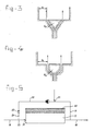
- Figure 3 shows an embodiment in which the body is formed by a cone.
- the main flow direction is in this case, via an acute angle, via a slit with the shape of a cone envelope having a flow section A0 to the lower-pressure chamber which has a larger flow section A1 with respect to the largest diameter of the cone.
- the body consists in the bottom section of a truncated cone.
- the flow is therefore initially deflected through 90° and then follows the path of the envelope of the cone and the part with the shape of a cylinder envelope adjacent thereto.
- Figure 5 shows a flotation tank 15 which is fed at 16 with dirty water in which the dirt is to be bonded into flocks by means of a flocculation process. Said water enters the tank 15 at 17. Clean water is drained via the pipeline 18. A part of the clean water, i.e. 10 to 50% is fed back via the pipeline 19 and is fed again to the dirty water at 20.
- the water from the pipeline 21, 22 can escape via the throttling element 24 and then forms a cloud of minute small bubbles in the dirty-water pipeline which debouches into the tank 15, as a result of which the flocculated particles are entrained upwards therewith and form a layer 25 which can be removed in a known manner.
- the throttling element 25 is located in the pipeline pipe which must obviously have a larger diameter than that of the throttling device and which must also fulfil the requirement that a lower pressure prevails therein. Between the throttling device 24 and the connection 20 to the dirty-water pipeline 16, a stable mist of minute small bubbles is thus formed which emerges with the dirty water into the flotation tank 15. Of cource a method is possible in which said pipeline pipe debouches directly into the flotation tank 15 separate from the dirty-water pipeline.
Landscapes
- Life Sciences & Earth Sciences (AREA)
- Engineering & Computer Science (AREA)
- Biotechnology (AREA)
- Chemical & Material Sciences (AREA)
- Organic Chemistry (AREA)
- Environmental & Geological Engineering (AREA)
- Water Supply & Treatment (AREA)
- Hydrology & Water Resources (AREA)
- Microbiology (AREA)
- Biodiversity & Conservation Biology (AREA)
- Chemical Kinetics & Catalysis (AREA)
- Nozzles (AREA)
- Physical Water Treatments (AREA)
- Control Of Throttle Valves Provided In The Intake System Or In The Exhaust System (AREA)
- Radiation-Therapy Devices (AREA)
- Crystals, And After-Treatments Of Crystals (AREA)
- Medicines That Contain Protein Lipid Enzymes And Other Medicines (AREA)
Priority Applications (1)
| Application Number | Priority Date | Filing Date | Title |
|---|---|---|---|
| AT87201735T ATE54123T1 (de) | 1986-09-11 | 1987-09-10 | Drosselapparat, verfahren fuer den gebrauch des drosselapparats und auch apparat fuer die anwendung des verfahrens. |
Applications Claiming Priority (2)
| Application Number | Priority Date | Filing Date | Title |
|---|---|---|---|
| NL8602297 | 1986-09-11 | ||
| NL8602297A NL8602297A (nl) | 1986-09-11 | 1986-09-11 | Smoorinrichting en werkwijze voor het toepassen daarvan. |
Publications (2)
| Publication Number | Publication Date |
|---|---|
| EP0259938A1 true EP0259938A1 (de) | 1988-03-16 |
| EP0259938B1 EP0259938B1 (de) | 1990-06-27 |
Family
ID=19848532
Family Applications (1)
| Application Number | Title | Priority Date | Filing Date |
|---|---|---|---|
| EP19870201735 Expired - Lifetime EP0259938B1 (de) | 1986-09-11 | 1987-09-10 | Drosselapparat, Verfahren für den Gebrauch des Drosselapparats und auch Apparat für die Anwendung des Verfahrens |
Country Status (8)
| Country | Link |
|---|---|
| US (1) | US4961857A (de) |
| EP (1) | EP0259938B1 (de) |
| AT (1) | ATE54123T1 (de) |
| CA (1) | CA1289848C (de) |
| DE (1) | DE3763400D1 (de) |
| ES (1) | ES2016835B3 (de) |
| GR (1) | GR3000771T3 (de) |
| NL (1) | NL8602297A (de) |
Cited By (1)
| Publication number | Priority date | Publication date | Assignee | Title |
|---|---|---|---|---|
| WO1995026930A1 (en) * | 1994-04-05 | 1995-10-12 | Wiser Oy | Method and equipment for treatment of a liquid flow to be cleaned and passed into a flotation plant or equivalent |
Families Citing this family (5)
| Publication number | Priority date | Publication date | Assignee | Title |
|---|---|---|---|---|
| DE19702181A1 (de) * | 1997-01-23 | 1998-07-30 | Marko Prof Dr Ing Zlokarnik | Neue Vorrichtung zur Begasungsflotation |
| CA2337975C (en) * | 2001-02-26 | 2010-11-09 | Hydroxyl Systems Inc. | Wastewater treatment system |
| US7534357B2 (en) | 2005-03-28 | 2009-05-19 | Navalis Environmental Systems, Llc | Dual-train wastewater reclamation and treatment system |
| US20070158276A1 (en) * | 2006-01-10 | 2007-07-12 | Navalis Environmental Systems, Llc | Method and Apparatus for Sequenced Batch Advanced Oxidation Wastewater Treatment |
| WO2011038452A1 (en) * | 2009-09-30 | 2011-04-07 | Ghd Pty Ltd | Liquid treatment system |
Citations (4)
| Publication number | Priority date | Publication date | Assignee | Title |
|---|---|---|---|---|
| FR1425387A (fr) * | 1964-12-03 | 1966-01-24 | Degremont | Dispositif pour réaliser l'injection de gaz dans un liquide |
| DE2453670A1 (de) * | 1973-11-13 | 1975-05-15 | Hamburger & Co Kg Georg | Einrichtung zum verteilen von gasen in fluessigkeiten |
| GB1593262A (en) * | 1977-09-21 | 1981-07-15 | Babcock Waster Treatment Ltd | Pressure reducing devices |
| DE3004223A1 (de) * | 1980-02-06 | 1981-08-13 | Günther 6056 Heusenstamm Heß | Vorrichtung zur verteilung von gasen und/oder daempfen in fluessigkeiten |
Family Cites Families (4)
| Publication number | Priority date | Publication date | Assignee | Title |
|---|---|---|---|---|
| US3645892A (en) * | 1969-06-13 | 1972-02-29 | Bowles Fluidics Corp | Aeration and foam separation employing vortex element |
| DE3008476A1 (de) * | 1980-03-05 | 1981-09-17 | Bayer Ag, 5090 Leverkusen | Verfahren zur flotation und verwendung von trichterduesen zur flotation |
| IT1133340B (it) * | 1980-09-26 | 1986-07-09 | Lussoria Antonietta Sciolla | Apparecchiatura per la miscelazione di gas in un liquido,particolarmente per la ossigenazione di acque inquinate |
| US4490248A (en) * | 1982-07-06 | 1984-12-25 | Filippov Jury M | Method and flotation machine for concentrating ores of non-ferrous metals |
-
1986
- 1986-09-11 NL NL8602297A patent/NL8602297A/nl not_active Application Discontinuation
-
1987
- 1987-09-10 ES ES87201735T patent/ES2016835B3/es not_active Expired - Lifetime
- 1987-09-10 EP EP19870201735 patent/EP0259938B1/de not_active Expired - Lifetime
- 1987-09-10 CA CA 546525 patent/CA1289848C/en not_active Expired - Lifetime
- 1987-09-10 AT AT87201735T patent/ATE54123T1/de not_active IP Right Cessation
- 1987-09-10 DE DE8787201735T patent/DE3763400D1/de not_active Expired - Lifetime
- 1987-10-19 US US07/110,185 patent/US4961857A/en not_active Expired - Lifetime
-
1990
- 1990-09-10 GR GR90400629T patent/GR3000771T3/el unknown
Patent Citations (4)
| Publication number | Priority date | Publication date | Assignee | Title |
|---|---|---|---|---|
| FR1425387A (fr) * | 1964-12-03 | 1966-01-24 | Degremont | Dispositif pour réaliser l'injection de gaz dans un liquide |
| DE2453670A1 (de) * | 1973-11-13 | 1975-05-15 | Hamburger & Co Kg Georg | Einrichtung zum verteilen von gasen in fluessigkeiten |
| GB1593262A (en) * | 1977-09-21 | 1981-07-15 | Babcock Waster Treatment Ltd | Pressure reducing devices |
| DE3004223A1 (de) * | 1980-02-06 | 1981-08-13 | Günther 6056 Heusenstamm Heß | Vorrichtung zur verteilung von gasen und/oder daempfen in fluessigkeiten |
Cited By (2)
| Publication number | Priority date | Publication date | Assignee | Title |
|---|---|---|---|---|
| WO1995026930A1 (en) * | 1994-04-05 | 1995-10-12 | Wiser Oy | Method and equipment for treatment of a liquid flow to be cleaned and passed into a flotation plant or equivalent |
| US5759408A (en) * | 1994-04-05 | 1998-06-02 | Wiser Oy | Method and equipment for treatment of a liquid flow to be cleaned and passed into a flotation plant or equivalent |
Also Published As
| Publication number | Publication date |
|---|---|
| DE3763400D1 (de) | 1990-08-02 |
| GR3000771T3 (en) | 1991-10-10 |
| ATE54123T1 (de) | 1990-07-15 |
| ES2016835B3 (es) | 1990-12-01 |
| EP0259938B1 (de) | 1990-06-27 |
| NL8602297A (nl) | 1988-04-05 |
| US4961857A (en) | 1990-10-09 |
| CA1289848C (en) | 1991-10-01 |
Similar Documents
| Publication | Publication Date | Title |
|---|---|---|
| US5332100A (en) | Column flotation method | |
| US5643459A (en) | Flotation method and apparatus | |
| US3608834A (en) | Gas diffuser | |
| CA2596329C (en) | Method and apparatus for contacting bubbles and particles in a flotation separation system | |
| US4165038A (en) | Device for atomizing and dispersing a fluid | |
| US4448681A (en) | Floatation arrangement | |
| CA2090619A1 (en) | Aeration of liquids | |
| US3947359A (en) | Aeration and mixing of liquids | |
| EP0259938B1 (de) | Drosselapparat, Verfahren für den Gebrauch des Drosselapparats und auch Apparat für die Anwendung des Verfahrens | |
| US4112026A (en) | Bubble generating apparatus | |
| US4531673A (en) | Spray jet polymer powder wetter | |
| US2702124A (en) | Water clarification system | |
| US2563211A (en) | Liquid proportioner | |
| KR101777655B1 (ko) | 순환유량 자동조절이 가능한 미세기포 발생노즐 | |
| WO1994006533A1 (en) | Inexpensive flow controller | |
| US2917295A (en) | Diffuser | |
| US3100810A (en) | Dissolving gas in liquid | |
| US3182801A (en) | Sewage treatment tank with aeration chamber and settling chamber | |
| KR930017603A (ko) | 가스-액체 접촉 시스템 | |
| CN102863039A (zh) | 一种加压溶气气浮的多重气泡混合系统 | |
| KR920004036A (ko) | 액체내에 부유하는 고체입자 덩어리를 분쇄하는 방법 및 장치 | |
| CA2628680C (en) | Method and apparatus for froth washing in flotation | |
| US3229448A (en) | Ultrasonic degasifying device | |
| CA1132268A (en) | Dual disc pressure release valve | |
| JPS6334773B2 (de) |
Legal Events
| Date | Code | Title | Description |
|---|---|---|---|
| PUAI | Public reference made under article 153(3) epc to a published international application that has entered the european phase |
Free format text: ORIGINAL CODE: 0009012 |
|
| AK | Designated contracting states |
Kind code of ref document: A1 Designated state(s): AT BE CH DE ES FR GB GR IT LI LU NL SE |
|
| 17P | Request for examination filed |
Effective date: 19880307 |
|
| 17Q | First examination report despatched |
Effective date: 19890420 |
|
| GRAA | (expected) grant |
Free format text: ORIGINAL CODE: 0009210 |
|
| AK | Designated contracting states |
Kind code of ref document: B1 Designated state(s): AT BE CH DE ES FR GB GR IT LI LU NL SE |
|
| REF | Corresponds to: |
Ref document number: 54123 Country of ref document: AT Date of ref document: 19900715 Kind code of ref document: T |
|
| ITF | It: translation for a ep patent filed | ||
| REF | Corresponds to: |
Ref document number: 3763400 Country of ref document: DE Date of ref document: 19900802 |
|
| ET | Fr: translation filed | ||
| REG | Reference to a national code |
Ref country code: GR Ref legal event code: FG4A Free format text: 3000771 |
|
| K2 | Correction of patent specification published | ||
| PLBE | No opposition filed within time limit |
Free format text: ORIGINAL CODE: 0009261 |
|
| STAA | Information on the status of an ep patent application or granted ep patent |
Free format text: STATUS: NO OPPOSITION FILED WITHIN TIME LIMIT |
|
| 26N | No opposition filed | ||
| ITTA | It: last paid annual fee | ||
| PGFP | Annual fee paid to national office [announced via postgrant information from national office to epo] |
Ref country code: GR Payment date: 19930930 Year of fee payment: 7 |
|
| PGFP | Annual fee paid to national office [announced via postgrant information from national office to epo] |
Ref country code: CH Payment date: 19931013 Year of fee payment: 7 |
|
| PGFP | Annual fee paid to national office [announced via postgrant information from national office to epo] |
Ref country code: SE Payment date: 19931015 Year of fee payment: 7 |
|
| PGFP | Annual fee paid to national office [announced via postgrant information from national office to epo] |
Ref country code: LU Payment date: 19931101 Year of fee payment: 7 |
|
| EPTA | Lu: last paid annual fee | ||
| PG25 | Lapsed in a contracting state [announced via postgrant information from national office to epo] |
Ref country code: LU Free format text: LAPSE BECAUSE OF NON-PAYMENT OF DUE FEES Effective date: 19940910 |
|
| PG25 | Lapsed in a contracting state [announced via postgrant information from national office to epo] |
Ref country code: SE Effective date: 19940911 |
|
| PG25 | Lapsed in a contracting state [announced via postgrant information from national office to epo] |
Ref country code: CH Effective date: 19940930 Ref country code: LI Effective date: 19940930 |
|
| EAL | Se: european patent in force in sweden |
Ref document number: 87201735.5 |
|
| PG25 | Lapsed in a contracting state [announced via postgrant information from national office to epo] |
Ref country code: GR Free format text: THE PATENT HAS BEEN ANNULLED BY A DECISION OF A NATIONAL AUTHORITY Effective date: 19950331 |
|
| REG | Reference to a national code |
Ref country code: CH Ref legal event code: PL Ref country code: GR Ref legal event code: MM2A Free format text: 3000771 |
|
| EUG | Se: european patent has lapsed |
Ref document number: 87201735.5 |
|
| REG | Reference to a national code |
Ref country code: GB Ref legal event code: IF02 |
|
| PGFP | Annual fee paid to national office [announced via postgrant information from national office to epo] |
Ref country code: NL Payment date: 20060831 Year of fee payment: 20 |
|
| PGFP | Annual fee paid to national office [announced via postgrant information from national office to epo] |
Ref country code: GB Payment date: 20060906 Year of fee payment: 20 |
|
| PGFP | Annual fee paid to national office [announced via postgrant information from national office to epo] |
Ref country code: DE Payment date: 20060907 Year of fee payment: 20 |
|
| PGFP | Annual fee paid to national office [announced via postgrant information from national office to epo] |
Ref country code: FR Payment date: 20060908 Year of fee payment: 20 |
|
| PGFP | Annual fee paid to national office [announced via postgrant information from national office to epo] |
Ref country code: AT Payment date: 20060913 Year of fee payment: 20 |
|
| PGFP | Annual fee paid to national office [announced via postgrant information from national office to epo] |
Ref country code: IT Payment date: 20060930 Year of fee payment: 20 |
|
| PGFP | Annual fee paid to national office [announced via postgrant information from national office to epo] |
Ref country code: ES Payment date: 20061030 Year of fee payment: 20 |
|
| PGFP | Annual fee paid to national office [announced via postgrant information from national office to epo] |
Ref country code: BE Payment date: 20061116 Year of fee payment: 20 |
|
| REG | Reference to a national code |
Ref country code: GB Ref legal event code: PE20 |
|
| NLV7 | Nl: ceased due to reaching the maximum lifetime of a patent |
Effective date: 20070910 |
|
| PG25 | Lapsed in a contracting state [announced via postgrant information from national office to epo] |
Ref country code: GB Free format text: LAPSE BECAUSE OF EXPIRATION OF PROTECTION Effective date: 20070909 |
|
| REG | Reference to a national code |
Ref country code: ES Ref legal event code: FD2A Effective date: 20070911 |
|
| BE20 | Be: patent expired |
Owner name: *NIJHUIS WATER B.V. Effective date: 20070910 |
|
| PG25 | Lapsed in a contracting state [announced via postgrant information from national office to epo] |
Ref country code: ES Free format text: LAPSE BECAUSE OF EXPIRATION OF PROTECTION Effective date: 20070911 Ref country code: NL Free format text: LAPSE BECAUSE OF EXPIRATION OF PROTECTION Effective date: 20070910 |