EP0259952B1 - Système de support de tête magnétique pour unité de disque à deux têtes - Google Patents
Système de support de tête magnétique pour unité de disque à deux têtes Download PDFInfo
- Publication number
- EP0259952B1 EP0259952B1 EP87306055A EP87306055A EP0259952B1 EP 0259952 B1 EP0259952 B1 EP 0259952B1 EP 87306055 A EP87306055 A EP 87306055A EP 87306055 A EP87306055 A EP 87306055A EP 0259952 B1 EP0259952 B1 EP 0259952B1
- Authority
- EP
- European Patent Office
- Prior art keywords
- leaf spring
- head
- gimbal
- spacer
- disk
- Prior art date
- Legal status (The legal status is an assumption and is not a legal conclusion. Google has not performed a legal analysis and makes no representation as to the accuracy of the status listed.)
- Expired
Links
- 230000009977 dual effect Effects 0.000 title claims description 3
- 125000006850 spacer group Chemical group 0.000 claims description 34
- 238000005096 rolling process Methods 0.000 claims description 11
- 230000007246 mechanism Effects 0.000 description 18
- 239000011435 rock Substances 0.000 description 4
- 230000008859 change Effects 0.000 description 3
- 238000006073 displacement reaction Methods 0.000 description 3
- 238000010276 construction Methods 0.000 description 2
- 206010012735 Diarrhoea Diseases 0.000 description 1
- 230000008878 coupling Effects 0.000 description 1
- 238000010168 coupling process Methods 0.000 description 1
- 238000005859 coupling reaction Methods 0.000 description 1
- 238000013016 damping Methods 0.000 description 1
- 230000000694 effects Effects 0.000 description 1
- 238000005516 engineering process Methods 0.000 description 1
- 238000005530 etching Methods 0.000 description 1
- 231100001261 hazardous Toxicity 0.000 description 1
- 238000003754 machining Methods 0.000 description 1
- 239000000463 material Substances 0.000 description 1
- 238000000034 method Methods 0.000 description 1
- 230000002093 peripheral effect Effects 0.000 description 1
- 230000036316 preload Effects 0.000 description 1
- 230000008569 process Effects 0.000 description 1
- 239000012858 resilient material Substances 0.000 description 1
Images




Classifications
-
- G—PHYSICS
- G11—INFORMATION STORAGE
- G11B—INFORMATION STORAGE BASED ON RELATIVE MOVEMENT BETWEEN RECORD CARRIER AND TRANSDUCER
- G11B5/00—Recording by magnetisation or demagnetisation of a record carrier; Reproducing by magnetic means; Record carriers therefor
- G11B5/48—Disposition or mounting of heads or head supports relative to record carriers ; arrangements of heads, e.g. for scanning the record carrier to increase the relative speed
- G11B5/58—Disposition or mounting of heads or head supports relative to record carriers ; arrangements of heads, e.g. for scanning the record carrier to increase the relative speed with provision for moving the head for the purpose of maintaining alignment of the head relative to the record carrier during transducing operation, e.g. to compensate for surface irregularities of the latter or for track following
-
- G—PHYSICS
- G11—INFORMATION STORAGE
- G11B—INFORMATION STORAGE BASED ON RELATIVE MOVEMENT BETWEEN RECORD CARRIER AND TRANSDUCER
- G11B17/00—Guiding record carriers not specifically of filamentary or web form, or of supports therefor
- G11B17/32—Maintaining desired spacing between record carrier and head, e.g. by fluid-dynamic spacing
-
- G—PHYSICS
- G11—INFORMATION STORAGE
- G11B—INFORMATION STORAGE BASED ON RELATIVE MOVEMENT BETWEEN RECORD CARRIER AND TRANSDUCER
- G11B21/00—Head arrangements not specific to the method of recording or reproducing
- G11B21/16—Supporting the heads; Supporting the sockets for plug-in heads
- G11B21/20—Supporting the heads; Supporting the sockets for plug-in heads while the head is in operative position but stationary or permitting minor movements to follow irregularities in surface of record carrier
-
- G—PHYSICS
- G11—INFORMATION STORAGE
- G11B—INFORMATION STORAGE BASED ON RELATIVE MOVEMENT BETWEEN RECORD CARRIER AND TRANSDUCER
- G11B5/00—Recording by magnetisation or demagnetisation of a record carrier; Reproducing by magnetic means; Record carriers therefor
- G11B5/48—Disposition or mounting of heads or head supports relative to record carriers ; arrangements of heads, e.g. for scanning the record carrier to increase the relative speed
- G11B5/488—Disposition of heads
- G11B5/4886—Disposition of heads relative to rotating disc
Definitions
- the invention relates to head supporting structure for disk driving apparatus for double-sided flexible disks, and more specifically to a support for a pair of heads which are utilized for reading and writing data on a flexible disk as is used in computers or word processors.
- a head carrier for the O-side of a flexible disk (hereinafter cited as media) as well as a head carrier for the side-1 of the media is described.
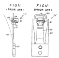
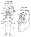
- Figs. 9 to 14 show an example of aforementioned prior art.
- Figs. 9 and 10 show a head carrying mechanism for 1-side surface of the media and Figs. 11, 12, one for O-side surface of the media respectively.
- the head carrying mechanism for side-0 surface and that for side-1 surface has the same structure except for the location of the head core 121 and pressure loading arm 125.
- the side 1 head 102 is held by a cantilever gimbal spring 103.
- the side 0 head 122 is held by a similar gimbal spring 123. Both head 102, 122 have at their rear face projections 104, 124, which abut on the spring 105, 125.
- the gimbal 103, the projection 104, and the spring 105 form an unseparable part.
- the gimbal 123, projection 124, and the spring 125 form another part as seen in Fig. 13.
- the gimbal 103 for the side l face, and the gimbal 123 for the side 0 face, is fixed on the members 107 and 127 respectively, which are fixed to the bottom of the arms 106 and 126 on either side of the media 100.
- the heads 102, 122 are moved into contact with the rotating media surfaces.
- the head carrying mechanism of the prior art shown in Fig. 13 has cantilever gimbals 103, 123, which are very flexible, and are capable of following a slight wobbling motion, radial or circumferential distortion of the media.
- the head is also capable of smaller head load force, i.e. force of contact of the head to a media surface.
- the head of the prior art has the drawback that good recording contact of the head can be easily damaged due to the wobbling of the head in case of excessive distortion or warp of the media, or inaccuracy of positioning of the media.
- the cantilever gimbal springs 103, 123 which carry the heads 102, 122 form cantilevers with one of their ends fixed to the arms 106, 126.
- the head carrying mechanism of the prior art has another drawback that complicate shape of the cantilever springs 103, 123 and loading springs require severe dimentional tolerances.
- the gimbal springs 103, 123 when they are removed from the assembly, show a spring back as shown in broken lines in Figs. 9, 11 to give a pre-load to the head carrier when it is assembled. This spring back of the gimbal spring causes difficulty in keeping the head in a correct position when it is assembled into a head carrying mechanism.
- Figs. 15-17 show another prior art as disclosed in U.S. Patent No. 4,151,573.
- a carriage 201 is provided on the side 0 face of a media 200. The carriage is movable in the radial direction with respect to the media.
- On the carriage 201 is fixed a button-shaped head 202. The head is in contact with the side 0 surface of the media.
- On the side 1 surface of the media is disposed a head 205 which is movable with respect to the media.
- the head 205 is fixed on a cantilever gimbal 204, which is held on an arm 203.
- One end of the arm 203 is hinged to the stem of the carriage 201.
- the head 205 has at its back a projection 206 which receives a loading force of a pivot 207 fixed on the arm 203.
- a coil spring 208 is provided on the stem of the arm to urge the pivot downward, or to the button-shaped head 202.
- the button-shaped head 202 for side 0 surface has a flat contact surface with its periphery chamfered. The contact surface of the head 202 is placed slightly above the level of the media surface to penetrate the media.
- the head carrying mechanism of the last mentioned prior art has found a wide use because the head of this type has many advantages e.g. simplicity in structure, high reliability of tracking notwithstanding wobblings of the media due to the fact that the head is fixed directly on the carriage and no displacement of the head occurs.
- the head of this type has still other drawbacks that the side 1 head 205 receives a relatively great mass of the arm 203, and tends to damage the media when the head is moved to the media surface too rapidly, or contact pressure on the media surface is liable to change by the posture of the carriage.
- Figs. 18-20 show still another prior art as is shown in Japanese Utility Model Publication No. 61-34596 (U.S. Patent No. 4,306,258).
- a head is disposed on each side of the media.
- the head carrier of each side is similar in construction.
- the head is fixed on the center of the planar spring gimbal 302.
- the contact pressure is obtained by the spring back of the gimbal 302.
- the head carrying mechanism prevent dislocation of the head as long as not deformation occurs on the head carrying arm 303.
- the head carrying mechanism assures a good recording contact of the head due to the spring rate of the gimbal in the direction normal to the media face, capability of the head of swing movement about the axis both circumferential and radial with respect to the media.
- the head carrying mechanism allows a radial dislocation of the head core gap as a result of swing motion about an axis parallel to the direction of the motion of the media.
- the dislocation of the head core gap occurs because the head slider, which is more than 2 mm in height, is tilted about the gimbal.
- the height of the head slider must be at lest 2 mm to allow for the jacket of the media.
- the above-mentioned radial wobbling of the head core causes a dislocation of the head, i.e. off-tracking.
- severe allowance is posed on the track margin and this allowance is especially severe when a high density recording is employed in which a number of tracks per inch or per mm is very large.
- follow up control of too rapid off-tracking, i.e. high frequency of off-tracking is impossible.
- Figs. 21-22 show the forth example of prior arts as shown in Japanese Patent Publication No. 58-43828, in which the heads 401, 402 is fixed at the center of gimbals 403, 404.
- One of the gimbals 404 is supported by radially spaced members at 404, 405.
- the head 401, 402 are supported on a carriage which is pivotable about an axis parallel to a radius of the media so that good circumferential follow-up of the heads can be achieved.
- the head is allowed to rock about a radial axis with respect to the media (pitching):
- This type of head carrying mechanism allows only a swing motion of the heads around an axis parallel to a radius of the disk through the head to disk contact point, and no swing motion around an axis parallel to a tangent to a disk track at the contact point nor wobbling in the direction perpendicular to the disk is allowed. This means a gap can occur, when the relative height changes, between the head core and the disk. Because the supports 405, 406 are fixed on a carriage 407 with resilient members therebetween, the head is allowed to rock in the Z-X plane (rolling), which is undesirable.
- Fig. 22 shows another type of gimbal which realizes similar functions as that shown in Fig. 21.
- the gimbal has a pair of bridges 411, 412, which allow the head to pitch. However, the gimbal does not allow the head to roll nor to move in the direction perpendicular to the disk face.
- Objects of the present invention are to overcome the drawbacks of the above mentioned four prior art examples, while keeping the advantages thereof, and in particular to make it possible to provide a head supporting structure which allows sufficient follow-up characteristics of the head, while substantially preventing off-tracking thereof, and to provide a head supporting structure for a high recording density head, i.e. a high circumferential density (BPI) as well as a high radial density (TP1 recording head.
- BPI circumferential density
- TP1 recording head high radial density
- EP-A-0012975 describes supporting structure for the dual magnetic heads of a disk drive system for a double-sided flexible disk, comprising: first and second read/write magnetic core heads disposed in use respectively at first and second sides of a flexible disk; first support means for supporting said first head, said first support means comprising a first leaf spring gimbal to allow the first head three degrees of freedom, namely movement (Z-Z) perpendicular to the plane of the disk, rolling about an axis (Y-Y) tangential to a disk track at the head to disk contact point and pitching about an axis (X-X) radial to the disk track at said contact point; and second support means for supporting said second head, said second support means including a second leaf spring gimbal;
- the second support means is similar to the first support means and thus have the same three degrees of freedom.
- said second support means comprises said second leaf spring gimbal carrying said second head and a further leaf spring structure coupled to said second leaf spring gimbal at first and second points spaced apart along said radial axis (X-X), to allow the second head two degrees of freedom, namely movement perpendicular to the plane of the disk and pitching about the radial axis (X-X) but substantially preventing rolling about the tangential axis (Y-Y).
- WO-A-81/01070 describes supporting structure having different support means for the first and second heads, the first head having freedom to pitch about the X-X axis and to roll about the Y-Y axis, but the second head only being able to move in the direction perpendicular to the disk along the Z-Z axis.
- Fig. 1 is a sectional view of a carrying mechanism according to the present invention.
- Fig. 2 is an isometric view of the carrying mechanism.
- the carriage has a pair of heads 1, 1' which will be described hereinafter.
- the carriage is slidable along guide bars in the direction normal to the surface of a flexible disk (which will be referred to as media 10).
- each of the heads 1, 1' has a read/write core for reading or writing codes magnetically on the media.
- the heads 1, 1' are fixed on a respective supporting member 3, 3'.
- the member 3 is fixed on a lower arm 12 at its peripheral portion.
- the member 3' is fixed on an upper arm 11.
- the central portion 3b of the members 3, 3' is capable of pitching (about the X-X axis) and rolling (about the Y-Y axis), wherein the X-X axis is radial to a disk track at the head to disk contact point and the Y-Y axis is tangential to the disk track at the contact point.
- the central portion 3b is movable in the Z-Z direction.
- the members 3, 3' function as gimbals.
- the head 1 is fixed on the central portion 3b of the gimbal 3 for recording contact with side 0 surface of the media.
- the central portion 3b of the gimbal spring for the surface "0" is supported at its back by a pair of vertical projection 5a, 5a of a cantilever spring 4 which can be manufactured by cutting off or etching process.
- the cantilever spring 4 has a horizontal extension disposed parallel to the Y-Y axis and a pair of legs extending normal to the X-Y plane which acts as a spacer 5 for the head.
- the bifurcated spacer 5 is secured on the gimbal 3 normally thereto at points 5a, 5a (more than two joint may be used).
- the height (h) of the spacer measures 2-3 mm.
- a projection 5a having tapered sides, which is inserted into apertures 6, 6.
- These legs 5, 5 and apertures 6, 6 are coupled together preventing any loose motion in the Y-Y direction.
- the coupling joint allows relative rotation around the axis X-X, the angle between the gimbal and the spacer can change. The change in the angle is possible when the cantilever spring 4 is made with a thin plate.
- the spacer 5 is shown as having a tongue 4 bent upwardly, which is made with a resilient material, the structure of the spacer is not limited to the embodiment.
- Figs. 3 and 4 show another example of spacer.
- a cantilever leaf spring 4 and a spacer 5 are made as separate parts.
- a projection 5c On the lower side of the spacer 5 is formed a projection 5c, which is inserted in a slot extending in Y direction whereby forming a non-slidable joint.
- the gimbal 3, cantilever spring 4 and the spacer 5 are assembled into a unit in the first step and the unit is then set on the arm 12.
- Figs. 5 and 6 show still another embodiment of a head carrying gimbal for side 0 head.
- a third gimbal spring 40 similar to the gimbal 3 is disposed under the gimbal 3, with spaced relation by means of a spacer 5, preventing rolling motion.
- the gimbal 40 which is spaced from the head carrying gimbal 3, and parallel thereto is secured at its periphery 40a.
- the central part 40b is movable in the Z direction, is capable of pitching, but not of rolling (rocking about Y-Y axis).
- the head carrying mechanism with two gimbals 3, 40, each being connected by means of the spacer 5, does not permit the head 1 to rock in the X-Z plane, but permits the head 1 to rock in Y-Z plane and to move in the Z-Z direction.
- the gimbal 3 ⁇ carrying the head 1 ⁇ for side 1 surface has at its upper side a projection.
- the biasing force of the spring 14 is exerted on the head 1 ⁇ .
- the spring 14 is secured at its other end 14a on the upper arm 11 by means of screws or other known means. This construction permits the side 1 head to move in relation to the arm 11 in the Z-Z direction.
- An adjusting screw 13 is used to adjust the biasing force of the spring 14.
- the leaf spring 4 extends in the Y-Y direction, and has a sufficient width in X-X direction to regist to a X-X deflection. Hence, the spacer 5 which is jointed to the spring 4, will not deflect in X-X direction thus preventing rocking motion of the gimbal in the Z-X plane.
- the head carrying mechanism assures a good follow up characteristic of the head even in case of wobbling of the media or misalignment of the media due to machining tolerances in the dimention, while keeping rigidity against rolling.
- the head carrying mechanism assures good lengthwise follow-up of the head because the spacer 5 is jointed to the gimbal 3 at plurality of points disposed in X-X direction which permit pitching of the head.
- the gimbals 3, 3 ⁇ carrying the heads 1, 1 ⁇ are described as two-axis square spring gimbals, other types of gimbals may be used, for example round spring gimbal or a cantilever gimbal as will be described below.
- Figs. 7-8 show another embodiment of the present invention, in which a cantilever gimbal 31 is employed.
- This type of gimbal has the drawback that it is liable to rotate.
- the head 1 is fixed on a cantilever leaf spring gimbal 31.
- Another cantilever spring 41 is disposed parallel to the gimbal 31 with a support member 7 ⁇ therebetween.
- the other end of each leaf spring is jointed with a spacer 5 thereby preventing rolling of the head.
- the space has a pair of projections 5a, 5a on the upper side, and each of these projections is inserted into either of two or more slots 6, 6, provided in radially spaced relation on the cantilever leaf spring gimbal 31.
- On the bottom side of the spacer 5 are provided a pair of projections 5c, 5c, and each of these projections is inserted into either of the slots 6 ⁇ , 6 ⁇ provided on a leaf spring 41.
- the head 1 is prevented of translational motion in the Z-X plane because a pair of cantilever leaf spring 31, 41, support member 7 ⁇ and the spacer 5 form a parallelogram. More than two projections may be provided on the bottom side of the spacer to make more the two joints between spacer and the cantilever leaf spring 41, thereby assuring more rigidity of the head against rotation. Due to the joints between spacer and gimbal aligned on the X-X axis, the head is capable of pitching and translational movement in Z-Y plane (shown in Fig. 8 in imaginary lines). The head carrying mechanism has sufficient rigidity against torsion about the longitudinal axis of the cantilever.
Landscapes
- Supporting Of Heads In Record-Carrier Devices (AREA)
Claims (9)
- Structure portante pour les deux têtes magnétiques d'un système de commande de disque destiné à un disque flexible à deux faces (10), comportant :
des première et seconde têtes de lecture/écriture à noyau magnétique (1', 1) agencées en service respectivement sur les première et seconde faces d'un disque flexible,
des premièrs moyens de support afin de supporter la première tête (1'), les premiers moyens de support comportant un premier cardan à ressort à lame (3') pour permettre à la première tête trois degrés de liberté, à savoir un mouvement (Z-Z) perpendiculaire au plan du disque, un roulis autour d'un axe (Y-Y) tangentiel à une piste de disque, au point de contact entre tête et disque, et un tangage autour d'un axe (X-X) radial à la piste de disque audit point de contact, et
des seconds moyens de support afin de supporter la seconde tête (1), les seconds moyens de support comportant un deuxième cardan à ressort à lame (3),
caractérisée en ce que :
les seconds moyens de support comprennent le deuxième cardan à ressort à lame (3), qui porte la seconde tête (1), et une autre structure à ressort à lame (4) reliée au deuxième cardan à ressort à lame (3) en des premier et second points (6) écartés l'un de l'autre le long de l'axe radial (X-X) pour permettre à la seconde tête deux degrés de liberté, à savoir un mouvement perpendiculaire au plan du disque et un tangage autour de l'axe radial (X-X) en empêchant essentiellement cependant un roulis autour de l'axe tangentiel (Y-Y). - Structure portante suivant la revendication 1, caractérisée en ce que l'autre structure à ressort à lame est un ressort à lame encastré (4) dont l'extrémité fixe est fixée le long d'une ligne parallèle à l'axe radial (X-X) et dont l'extrémité libre (5) est raccordée à la partie centrale du deuxième cardan à ressort à lame (3) auxdits premier et second points (6) écartés l'un de l'autre le long de l'axe radial (X-X).
- Structure portante suivant la revendication 1, caractérisée en ce que l'autre structure à ressort à lame (4) comporte un ressort à lame encastré (4) dont l'extrémité libre est fixée le long d'une ligne parallèle à l'axe radial précité et dont l'extrémité libre est reliée à la partie centrale du deuxième cardan à ressort à lame au moyen d'une entretoise (5), une extrémité (5c) de l'entretoise étant raccordée par au moins une articulation à l'extrémité libre du ressort à lame encastré (4), l'autre extrémité (5a) de l'entretoise étant raccordée par des première et seconde articulations au deuxième cardan a ressort à lame, aux premier et second points (6).
- Structure portante suivant la revendication 3, caractérisée en ce que le deuxième cardan à ressort à lame (3), le ressort à lame encastré (4) et l'entretoise (5) sont assemblés en un dispositif à monter sur un bras de chariot (12) du système de commande de disque.
- Structure portante suivant la revendication 1, caractérisée en ce que l'autre struture à ressort à lame comporte un troisième cardan à ressort à lame (40), s'étendant parallèlement à et étant écarté du deuxième cardan à ressort à lame (3), et une entretoise (5) reliant les parties centrales des deuxième et troisième cardans à ressort à lame, une extrémité (6') de l'entretoise étant raccordée par au moins une articulation au troisième cardan à ressort à lame (40) et l'autre extrémité (5a) de l'entretoise étant raccordée par des première et seconde articulations au deuxième cardan à ressort à lame (3), aux premier et second points (6) susdits.
- Structure portante suivant l'une quelconque des revendications 2 à 5. caractérisée en ce que les articulations des premier et second points (6) comportent chacune une fente (6), formée dans la partie centrale du deuxième cardan à ressort à lame (3) et alignée le long de l'axe radial (X-X) précité, et une saillie à section décroissante (5a) introduite dans cette fente.
- Structure portante suivant la revendication 1, caractérisée en ce que le deuxième cardan à ressort a lame (31) et l'autre structure à ressort a lame (4) comportent une paire de cardans à ressort à lame encastrés (31, 41), qui s'étendent parallèlement et à distance l'un de l'autre, et en ce qu'une entretoise (5) relie les extrémités libres des cardans à ressort à lame encastrés, chaque extrémité (5a, 5c) de l'entretoise étant raccordée par des première et seconde articulations à des premier et second points écartés radialement (6, 6') des cardans à ressort à lame encastrés respectifs, pour former une liaison à parallélogramme.
- Structure portante suivant la revendication 7, caractérisée en ce que chaque articulation comporte une fente (6, 6'), alignée radialement et formée dans le cardan à ressort à lame encastré respectif (31, 41), et une saillie à section décroissante (5a, 5c), sur l'entretoise, introduite dans cette fente.
- Structure portante suivant l'une ou l'autre des revendications 7 et 8, caractérisée en ce que la paire de cardans à ressort à lame encastrés (31, 41) et l'entretoise (5) sont assemblés en un dispositif à monter sur un bras de chariot (12) du système de commande de disque.
Applications Claiming Priority (2)
| Application Number | Priority Date | Filing Date | Title |
|---|---|---|---|
| JP61163267A JPS6320763A (ja) | 1986-07-11 | 1986-07-11 | 両面型フレキシブルデイスク駆動装置におけるヘツド支持構造 |
| JP163267/86 | 1986-07-11 |
Publications (2)
| Publication Number | Publication Date |
|---|---|
| EP0259952A1 EP0259952A1 (fr) | 1988-03-16 |
| EP0259952B1 true EP0259952B1 (fr) | 1991-09-18 |
Family
ID=15770557
Family Applications (1)
| Application Number | Title | Priority Date | Filing Date |
|---|---|---|---|
| EP87306055A Expired EP0259952B1 (fr) | 1986-07-11 | 1987-07-08 | Système de support de tête magnétique pour unité de disque à deux têtes |
Country Status (4)
| Country | Link |
|---|---|
| US (1) | US4807070A (fr) |
| EP (1) | EP0259952B1 (fr) |
| JP (1) | JPS6320763A (fr) |
| DE (1) | DE3773094D1 (fr) |
Families Citing this family (19)
| Publication number | Priority date | Publication date | Assignee | Title |
|---|---|---|---|---|
| JPS62162287A (ja) * | 1986-01-10 | 1987-07-18 | Hitachi Maxell Ltd | 磁気ヘツド |
| JPS63273265A (ja) * | 1987-04-30 | 1988-11-10 | Toshiba Corp | 磁気記録再生装置の磁気ヘツド支持機構 |
| JPS6432466A (en) * | 1987-07-29 | 1989-02-02 | Konishiroku Photo Ind | Head supporting structure for double face type flexible disk driving device |
| DE68914026T2 (de) * | 1988-05-18 | 1994-07-07 | Fujitsu Ltd | Kopfaufhängungsvorrichtung für ein Aufzeichnungsgerät. |
| FR2638011B1 (fr) * | 1988-10-18 | 1991-06-07 | Kodak Pathe | Suspension pour tetes magnetiques |
| US5245093A (en) * | 1989-01-26 | 1993-09-14 | Abb Lummus Crest Inc. | Reaction processes in a multi-stage fluidized bed |
| US6600631B1 (en) | 1989-11-27 | 2003-07-29 | Censtor Corp. | Transducer/flexure/conductor structure for electromagnetic read/write system |
| US5166847A (en) * | 1990-04-05 | 1992-11-24 | Seagate Technology, Inc. | Reduced stick/slip load arm assembly having a coating with a low frictional coefficient |
| JP2731451B2 (ja) * | 1990-06-29 | 1998-03-25 | アルプス電気株式会社 | 磁気ディスク装置 |
| US5079659A (en) * | 1990-07-06 | 1992-01-07 | Seagate Technology, Inc. | Gimbal for supporting a hydrodynamic air bearing slider |
| US5225950A (en) * | 1991-02-25 | 1993-07-06 | Seagate Technology, Inc. | Gimbal having stiffness properties |
| JP2587162B2 (ja) * | 1992-01-22 | 1997-03-05 | 富士通株式会社 | 磁気ディスク装置のヘッドアーム |
| CN1151078A (zh) * | 1994-11-16 | 1997-06-04 | 株式会社日立制作所 | 磁盘装置 |
| US5771136A (en) * | 1996-05-23 | 1998-06-23 | Hutchinson Technology Incorporated | Suspension assembly for mounting a head slider having a flexure with a shock limiter |
| US6046883A (en) * | 1996-12-31 | 2000-04-04 | Hutchinson Technology Incorporated | Head suspension having a flexure motion limiter |
| US6005750A (en) * | 1997-11-12 | 1999-12-21 | Hutchinson Technology Incorporated | Head suspension including coupled flexure and damper constraint layer |
| GB2340943B (en) * | 1998-08-28 | 2000-07-19 | Bank Of England | Improvements in and relating to sheet material inspection apparatus and methods |
| US6172853B1 (en) | 1999-05-20 | 2001-01-09 | Hutchinson Technology Incorporated | Head suspension having a near dimple motion limiter |
| US6545844B1 (en) | 1999-10-19 | 2003-04-08 | Seagate Technology Llc | Clock head with spacer |
Family Cites Families (16)
| Publication number | Priority date | Publication date | Assignee | Title |
|---|---|---|---|---|
| FR2309012A1 (fr) * | 1975-04-21 | 1976-11-19 | Ibm | Memoire a disque magnetique flexible |
| US4151573A (en) * | 1977-06-13 | 1979-04-24 | Tandon Magnetics Corp. | Magnetic recording device for double sided media |
| SU748502A1 (ru) * | 1977-06-23 | 1980-07-15 | Предприятие П/Я В-2867 | Держатель плавающей магнитной головки |
| FR2426943A1 (fr) * | 1978-05-26 | 1979-12-21 | Cii Honeywell Bull | Plate-forme d'au moins un transducteur de lecture et/ou d'enregistrement d'un support d'informations |
| JPS6042542B2 (ja) * | 1978-12-01 | 1985-09-24 | 株式会社日立製作所 | 磁気ヘッド支持装置 |
| US4291350A (en) * | 1978-12-29 | 1981-09-22 | International Business Machines Corporation | Spring suspension for magnetic transducer |
| GB2071395A (en) * | 1979-10-05 | 1981-09-16 | Nortronics Co | Transducers and supporting arm assembly for double sided floppy disc |
| US4327388A (en) * | 1980-02-15 | 1982-04-27 | International Business Machines Corporation | Transducer-carriage assembly with spring suspension |
| US4363045A (en) * | 1980-10-20 | 1982-12-07 | New World Computer Company, Inc. | Magnetic transducer suspension device |
| US4379315A (en) * | 1980-10-21 | 1983-04-05 | Applied Magnetics Corporation | Carriage loading arm assembly having two magnetic transducers for a double sided floppy disc |
| JPS5843828B2 (ja) * | 1981-04-09 | 1983-09-29 | 日本電信電話株式会社 | 両面媒体用磁気記録装置における磁気ヘッド支持装置 |
| JPS5956259A (ja) * | 1982-09-27 | 1984-03-31 | Tokyo Electric Co Ltd | フロツピイデイスクの磁気ヘツド保持装置 |
| JPS59177065U (ja) * | 1983-05-12 | 1984-11-27 | オムロン株式会社 | 磁気ヘツドの保持装置 |
| US4651245A (en) * | 1984-07-19 | 1987-03-17 | Ricoh Company, Ltd. | Deflection limited magnetic head supporting structure |
| JPS61139975A (ja) * | 1984-12-10 | 1986-06-27 | Alps Electric Co Ltd | 磁気ヘツド組立体の製造方法 |
| US4724500A (en) * | 1986-08-14 | 1988-02-09 | Tandon Corporation | Mechanism for preventing shock damage to head slider assemblies and disks in rigid disk drive |
-
1986
- 1986-07-11 JP JP61163267A patent/JPS6320763A/ja active Pending
-
1987
- 1987-07-08 DE DE8787306055T patent/DE3773094D1/de not_active Expired - Fee Related
- 1987-07-08 EP EP87306055A patent/EP0259952B1/fr not_active Expired
- 1987-07-09 US US07/071,418 patent/US4807070A/en not_active Expired - Fee Related
Also Published As
| Publication number | Publication date |
|---|---|
| EP0259952A1 (fr) | 1988-03-16 |
| JPS6320763A (ja) | 1988-01-28 |
| DE3773094D1 (de) | 1991-10-24 |
| US4807070A (en) | 1989-02-21 |
Similar Documents
| Publication | Publication Date | Title |
|---|---|---|
| EP0259952B1 (fr) | Système de support de tête magnétique pour unité de disque à deux têtes | |
| US4151573A (en) | Magnetic recording device for double sided media | |
| EP0362072B1 (fr) | Mécanisme de suspension d'un patin porte-tête pour un appareil d'enregistrement | |
| US4620251A (en) | Magnetic transducer support structure | |
| EP0442225B1 (fr) | Assemblage tête/cardan avec élément élastique plat croisé à basse rigidité | |
| EP0060358B1 (fr) | Dispositif de support d'une tête et montage de support d'une tête pour mémoires à disque | |
| US5570261A (en) | Transducer suspension system | |
| US5790347A (en) | Head suspension load beam and flexure construction for reducing structural height | |
| US6233121B1 (en) | Magnetic disk drive suspension pitch motion limiter | |
| US4379315A (en) | Carriage loading arm assembly having two magnetic transducers for a double sided floppy disc | |
| US5138507A (en) | Disk head assembly flexure with improved motion stability | |
| EP0397896B1 (fr) | Suspension d'une tête magnetique à profil compact | |
| JPH06215511A (ja) | 一体のロードビーム及びフレクシャを備えて製造される磁気ヘッド懸架装置アセンブリ | |
| US4876623A (en) | Magnetic disc device with gimbal spring having variable elastic characteristics | |
| US4740854A (en) | Flexure seat for a transducer head of a magnetic disk apparatus | |
| EP0034245B1 (fr) | Assemblage à chariot pour transducteur | |
| US5008768A (en) | Disk head assembly flexure with sloped ramp support structure | |
| WO1983001860A1 (fr) | Dispositif de chargement et de retraction de tetes magnetiques | |
| US5659448A (en) | Magnetic head supporting mechanism including a slider fixed to a slider spacer by a fixing area smaller than a contact area | |
| US5455727A (en) | Transducer suspension assembly with a first pair of flanges for raising the resonant frequency and a second pair of flanges for increasing stiffness | |
| JP2678401B2 (ja) | 直列型の偏りヘッド取付用サスペンション | |
| US4943881A (en) | Head supporting structure in disk drive system for double sided flexible disk | |
| US4841396A (en) | Double gimbal magnetic head supporting mechanism for a floppy disk drive | |
| US4855851A (en) | Head suspension for magnetic recording | |
| US7218479B2 (en) | Head support device with bearing and elastic member |
Legal Events
| Date | Code | Title | Description |
|---|---|---|---|
| PUAI | Public reference made under article 153(3) epc to a published international application that has entered the european phase |
Free format text: ORIGINAL CODE: 0009012 |
|
| AK | Designated contracting states |
Kind code of ref document: A1 Designated state(s): BE DE FR GB IT NL |
|
| 17P | Request for examination filed |
Effective date: 19880905 |
|
| 17Q | First examination report despatched |
Effective date: 19900108 |
|
| RAP3 | Party data changed (applicant data changed or rights of an application transferred) |
Owner name: KONICA CORPORATION |
|
| GRAA | (expected) grant |
Free format text: ORIGINAL CODE: 0009210 |
|
| AK | Designated contracting states |
Kind code of ref document: B1 Designated state(s): BE DE FR GB IT NL |
|
| PG25 | Lapsed in a contracting state [announced via postgrant information from national office to epo] |
Ref country code: IT Free format text: LAPSE BECAUSE OF FAILURE TO SUBMIT A TRANSLATION OF THE DESCRIPTION OR TO PAY THE FEE WITHIN THE PRE;WARNING: LAPSES OF ITALIAN PATENTS WITH EFFECTIVE DATE BEFORE 2007 MAY HAVE OCCURRED AT ANY TIME BEFORE 2007. THE CORRECT EFFECTIVE DATE MAY BE DIFFERENT FROM THE ONE RECORDED.SCRIBED TIME-LIMIT Effective date: 19910918 Ref country code: FR Effective date: 19910918 |
|
| REF | Corresponds to: |
Ref document number: 3773094 Country of ref document: DE Date of ref document: 19911024 |
|
| EN | Fr: translation not filed | ||
| PLBE | No opposition filed within time limit |
Free format text: ORIGINAL CODE: 0009261 |
|
| STAA | Information on the status of an ep patent application or granted ep patent |
Free format text: STATUS: NO OPPOSITION FILED WITHIN TIME LIMIT |
|
| 26N | No opposition filed | ||
| PGFP | Annual fee paid to national office [announced via postgrant information from national office to epo] |
Ref country code: GB Payment date: 19960701 Year of fee payment: 10 |
|
| PGFP | Annual fee paid to national office [announced via postgrant information from national office to epo] |
Ref country code: DE Payment date: 19960712 Year of fee payment: 10 |
|
| PGFP | Annual fee paid to national office [announced via postgrant information from national office to epo] |
Ref country code: NL Payment date: 19960729 Year of fee payment: 10 |
|
| PGFP | Annual fee paid to national office [announced via postgrant information from national office to epo] |
Ref country code: BE Payment date: 19960828 Year of fee payment: 10 |
|
| PG25 | Lapsed in a contracting state [announced via postgrant information from national office to epo] |
Ref country code: GB Free format text: LAPSE BECAUSE OF NON-PAYMENT OF DUE FEES Effective date: 19970708 |
|
| PG25 | Lapsed in a contracting state [announced via postgrant information from national office to epo] |
Ref country code: BE Free format text: LAPSE BECAUSE OF NON-PAYMENT OF DUE FEES Effective date: 19970731 |
|
| BERE | Be: lapsed |
Owner name: KONICA CORP. Effective date: 19970731 |
|
| PG25 | Lapsed in a contracting state [announced via postgrant information from national office to epo] |
Ref country code: NL Free format text: LAPSE BECAUSE OF NON-PAYMENT OF DUE FEES Effective date: 19980201 |
|
| GBPC | Gb: european patent ceased through non-payment of renewal fee |
Effective date: 19970708 |
|
| NLV4 | Nl: lapsed or anulled due to non-payment of the annual fee |
Effective date: 19980201 |
|
| PG25 | Lapsed in a contracting state [announced via postgrant information from national office to epo] |
Ref country code: DE Free format text: LAPSE BECAUSE OF NON-PAYMENT OF DUE FEES Effective date: 19980401 |