EP0259958A2 - Appareil électronique avec possibilité d'extension pour l'entrée de données - Google Patents
Appareil électronique avec possibilité d'extension pour l'entrée de données Download PDFInfo
- Publication number
- EP0259958A2 EP0259958A2 EP87306215A EP87306215A EP0259958A2 EP 0259958 A2 EP0259958 A2 EP 0259958A2 EP 87306215 A EP87306215 A EP 87306215A EP 87306215 A EP87306215 A EP 87306215A EP 0259958 A2 EP0259958 A2 EP 0259958A2
- Authority
- EP
- European Patent Office
- Prior art keywords
- standard
- key
- keys
- optional
- program
- Prior art date
- Legal status (The legal status is an assumption and is not a legal conclusion. Google has not performed a legal analysis and makes no representation as to the accuracy of the status listed.)
- Granted
Links
Images


Classifications
-
- G—PHYSICS
- G06—COMPUTING OR CALCULATING; COUNTING
- G06F—ELECTRIC DIGITAL DATA PROCESSING
- G06F3/00—Input arrangements for transferring data to be processed into a form capable of being handled by the computer; Output arrangements for transferring data from processing unit to output unit, e.g. interface arrangements
- G06F3/01—Input arrangements or combined input and output arrangements for interaction between user and computer
- G06F3/02—Input arrangements using manually operated switches, e.g. using keyboards or dials
- G06F3/023—Arrangements for converting discrete items of information into a coded form, e.g. arrangements for interpreting keyboard generated codes as alphanumeric codes, operand codes or instruction codes
-
- G—PHYSICS
- G06—COMPUTING OR CALCULATING; COUNTING
- G06F—ELECTRIC DIGITAL DATA PROCESSING
- G06F3/00—Input arrangements for transferring data to be processed into a form capable of being handled by the computer; Output arrangements for transferring data from processing unit to output unit, e.g. interface arrangements
- G06F3/01—Input arrangements or combined input and output arrangements for interaction between user and computer
- G06F3/02—Input arrangements using manually operated switches, e.g. using keyboards or dials
- G06F3/0202—Constructional details or processes of manufacture of the input device
- G06F3/021—Arrangements integrating additional peripherals in a keyboard, e.g. card or barcode reader, optical scanner
-
- G—PHYSICS
- G06—COMPUTING OR CALCULATING; COUNTING
- G06F—ELECTRIC DIGITAL DATA PROCESSING
- G06F3/00—Input arrangements for transferring data to be processed into a form capable of being handled by the computer; Output arrangements for transferring data from processing unit to output unit, e.g. interface arrangements
- G06F3/01—Input arrangements or combined input and output arrangements for interaction between user and computer
- G06F3/02—Input arrangements using manually operated switches, e.g. using keyboards or dials
- G06F3/023—Arrangements for converting discrete items of information into a coded form, e.g. arrangements for interpreting keyboard generated codes as alphanumeric codes, operand codes or instruction codes
- G06F3/0238—Programmable keyboards
Definitions
- the present invention relates generally to an electronic device which can be modified into a functionally expanded model by addition of optional components, and a method for functionally expanding such an electronic device. More particularly, the invention is concerned with a data input device such as keyboards for personal computers and word processors, and a method for functionally expanding such a data input device, by adding to a standard model optional keys or other operator-controlled components.
- a data input device such as keyboards for personal computers and word processors
- a method for functionally expanding such a data input device by adding to a standard model optional keys or other operator-controlled components.
- an electronic device there arises a need of modifying a standard model to a functionally different model, by adding optional components to standard components provided on the standard model, or by replaciang at least one of the standard components with at least one different component.
- data processing equipments such as a personal computer, a word processing device and an electronic typewriter.
- it is required to increase the number of data signals that can be entered through the keyboard of the equipment.
- keys provided on the keyboard.
- An alternative known method is to increase the number of operation modes of the existing keys, for instance, by concurrently operating two or more keys, or changing the operation time of a key in two or more steps.
- a further object of the invention is to provide a method of adding a group of optional keys to a standard keyboard to obtain a functionally expanded keyboard, with a comparatively simple procedure.
- an electronic device having a plurality of standard components which render the device operable as a standard model, and wherein the standard model may be converted into a functionally different modified model by adding at least one additional component and/or replacing at least one of the standard components with at least one different component
- the electronic device comprising: (a) printed-circuit board having wirings which are connected to the standard components and adapted to transfer signals corresponding to the standard components; (b) a program memory for storing at least a standard control program for handling the signals from the wirings connected to the standard components, so as to enable the- electronic device to operate as the standard model; and (c) program-changing means for changing the standard control program into a modified control program which enables the electronic device to operate as the functionally different modified model.
- the standard model can be readily functionally expanded or modified by simply adding an optional component or components or replacing the standard component or components with other components.
- the functional modification of the standard model into the modified model does not require the addition of a new exclusively designed computer, since the program-changing means incorporated in the standard model is adapted to change, upon modification of the standard model, the standard control program into a modified control program which enables the electronic device to operate as the functionally modified or expanded model.
- the functional modification or expansion of the standard model into the modified or expanded model can be effected at a comparatively reduced cost.
- the program-changing means may comprise means for holding the program memory replaceably with an optional program memory for storing the modified control program.
- a data input device having a plurality of standard operator-controlled components which render the device operable as a standard model, and wherein the standard model may be converted into a functionally different modified model by adding at least one additional operator-controlled component and/or replacing at least one of the standard operator-controlled components with at least one different operator-controlled component
- the data input device comprising: (a) a printed-circuit board having wirings which are connected to the standard f operator-controlled components and adapted to transfer signals corresponding to the standard operator-controlled ⁇ components; (b) a program memory for storing at least a standard control program for handling the signals from the wirings connected to the standard operator-controlled components, so as to enable the data input device to operate as the standard model; and (c) program-changing means for changing the standard control program into a modified control program which enables the data input device to operate as the functionally different modified model.
- the number of data signals that can be entered can be readily increased simply by adding an optional operator-controlled components to the standard model, without having to use an exclusively designed new computer in addition to the exisiting computer incorporated in the standard model. Yet, the obtained functionally modified or expanded model remains easy to operate.
- the data input device consists of a standard keyboard having a plurality of standard finger-operated keys as the standard operator-controlled components, which is converted into a modified keyboard by adding at least one additional finger-operated key.
- a group consisting of the at least one additional finger-operated key constitutes a group of optional keys
- the standard control program includes a standard-key scanning routine for scanning the standard finger-operated keys
- the modified control program includes an optional-key scanning routine for scanning the group of optional keys, as well as the standard-key scanning routine.
- the program-changing means comprises means for holding the program memory replaceably with a program memory for storing the modified control program.
- the program memory incorporated in the standard keyboard stores a key-scanning program ' which includes in combination both of the standard control program and the modified control program
- the program-changing means includes signal-generating means which generates a signal whose state is changed before and after the addition of the group of optional keys, the program-changing means changing the standard control program to the modified control program, based on the state of the signal-generating means.
- the program memory of the standard model also stores the program for effecting the optinal-key scanning routine for scanning the optional keys which will be provided on the functionally modified or expanded model. Storage of the optional-key scanning routine as well as the standard-key scanning routine in the program memory causes substantially no increase in the cost of the standard model keyboard.
- the signal-generating means for generating a signal indicative of the addition of the optional keys will be made at a relatively low cost.
- the signal-generating means may be a switch whose state is changed upon installation of the group of optional keys in place.
- the optional-key scanning routine will not be executed on the standard model, or until the standard model is modified into the functionally expanded model equipped with the optional keys. Therefore, the scanning of the standard keys on the standard model can be effected without a waste of time for the optional-key scanning routine.
- the program-changing means converts the standard control program to the modified control program upon installation of the optional keys
- the modified control program includes a program for handling the signal generated from the wiring of the printed-circuit board connected to at least one of the standard operator-controlled keys, as a signal having a different significance.
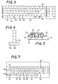
- a word processor which may be equipped with optional keys according the principle of the present invention.
- This word processor consists of two stand-alone units, i.e., a keyboard-printer unit 10, and a display unit 12.
- the keyboard-printer unit 10 includes a keyboard 14 and a printer 16.
- a control circuit 18 as illustrated in Fig. 2.
- the display unit 12 includes a cathode ray tube (CRT) display 20.
- CTR cathode ray tube
- the keyboard 14 is connected to the keyboard driver 44, so that data entered through each one of the operated keys on the keyboard 14 is applied through the keyboard driver 44 to the working memory 34 and the text memory 38.
- the character generator 43 supplies the printer driver 46 and the display . controller 48 with character pattern data representative of characters of the text data stored in the text memory 38.
- the printer driver 46 and display controller 48 have respective memories for storing the received character pattern data, from which the printer 16 and the CRT display 20 are operated to print and display the data entered through the keyboard 14.
- the CRT display 20 and the display controller 48 are both provided on the display unit 12.
- the keyboard 14 has a multiplicity of character keys 50, and a plurality of function keys which consists of two groups.
- the first group of function keys consists of such function keys that are particularly frequently used.
- the first group of function keys, which are disposed near the character keys 50, includes a space bar 52, a CODE key 54, a carriage return key 56 and a SHIFT key 58.
- the second group of function keys is disposed in another section of the keyboard separate from the character keys 50, i.e., in a section at the right-hand side end of the keyboard 14, as indicated in Fig. 3. This second group of function keys consists of two sub-groups.
- the movable and stationary contacts constitute a switching circuit of a key switch.
- the thus constructed blind key structure is provided on the standard keyboard 14A, so that the standard keyboard 14A may be modified or functionally expanded into the delux keyboard 14B, when necessary.
- the blind cap 71 has downward bosses 78 extending from its lower surface, while the keystem 76 of each optional key has a through-hole 80.
- the blind cap 71 is fixed on the upper casing 82 such that the bosses 78 fixedly engage the upper end portions of the through-holes 80 of the optional keys 66, 68, 70.
- the blind cap 71 serves as a disabling member for preventing an access of an operator of the keyboard 14A to the keystem 76, for inhibiting the keystem 76 to be moved between its operated- and non-operated positions on the standard keyboard 14A.
- the program memory 32 stores various control programs, which include a key-scanning program as shown in the flow chart of Fig. 6, wherein steps of operations are indicated by numerals following letter S.
- step Sl is executed to determine whether the optional keys have been added, or not. Since the switch 41 is open as long as the keyboarad -14 remains the standard keyboard 14A, a negative decision ("NO") is made in step Sl. Consequently, the control skips steps S2 and S3 (which will be described) and directly goes to step S4 wherein an initial value equal to the number of the standard keys is set in a standard-key scanning counter provided in the working memory 34.
- step S6 decrement the standard-key scanning counter
- step S7 to check if the scanning counter has been zeroed or not. Since the scanning operation of the standard keys has just been started (since this is the first scanning cycle to scan the first standard key), the decision in step S7 is obviously negative ("NO"), whereby the control returns to step S5 to start the next scanning cycle for the N-key roll-over scanning of the second standard key which corresponds to the current count of the standard-key scanning counter. Then, the control goes to step S6 wherein the scanning counter is further decremented, and to step S7 to check if the counter has been zeroed or not. In the same manner, steps S5-S7 are executed repeatedly until all the standard keys have been scanned.
- step S7 the standard-key scanning operation is terminated when the standard-key scanning counter has been zeroed and an affirmative decision ("YES") is obtained in step S7.
- the control returns to step Sl. Since the decision in step Sl is still negative (“NO"), the control goes to step S4 to set again the standard-key scanning counter to the initial value, and to steps S5-S7. At the end of this second scanning operation of all standard keys, the control again returns to step Sl.
- the code data corresponding to the operated-standard key is applied to the working memory 34 and the text memory 38.
- each keytop has a boss similar to the boss 78 of the blind cap 71, and the boss of the keytop is inserted in the upper portion of the through-hole 80 formed in the respective keystem 76.
- the conventional procedure requires: removing the printed-circuit board 72; removing a blind cap secured to the underside of the upper casing 82; attaching the keystem 76 and the elastomeric cup member 74; securing again the printed-circuit board 72 to the upper casing 82; and fixing a keytop to the keystem 76.
- the standard keyboard 14A is expanded to the delux keyboard 14B.
- step S9 is executed to set an initial value in an optional-key scanning counter in the working memory 34. This initial value is equal to the number of the optional keys which are provided on the delux keyboard 14B.
- one of the optional keys which has an identification number equal to the initial value set in the optional-key scanning counter is scanned in a 2-key roll-over method.
- this scanning method is used for detecting whether any particular key has been activated, even if two keys including the particular key to be detected are successively operated, such that the second key is operated before the previously operated first key has been released. In this scanning method, however, it is impossible to detect the operation of a key if three or more keys are successively operated in the manner indicated above.
- the 2-key roll-over scanning is simpler than the N-key roll-over method.
- step Sll the optional-key scanning counter is decremented in step Sll, and this step is followed by step S12 to check if the scanning counter has been zeroed or not.
- Steps S10 and Sll are repeated until an affirmative decision ("YES") is obtained in step S12, namely, until all the optional keys' have been scanned:
- the control returns to step Sl and to step S2. Since the optional-key flag has been reset in step S8, a negative decision is obtained in step S2. Therefore, steps S3-S7 are again executed.
- steps S3-S7 are again executed.
- the same standard-key and optional-key scanning operations as described above are alternately repeated. If any one of the standard and optional keys is operated, the corresponding code data is applied to the working memory 34 and the text memory 38.
- both the standard keys and the optional keys may be scanned with the computer incorporated in the standard keyboard 14A, which computer includes the CPU 30, program memory 32, working memory 34 and common data bus 40.
- the optional keys can be scanned in a comparatively short time with a simpler arrangement, since the 2-key roll-over scanning of the optional keys is simpler than the .N-key roll-over scanning used for the standard keys. More specifically, the N-key roll-over scanning requires a diode for each of the keys in a key-matrix circuit on the printed-circuit board, in order to prevent possible erroneous detection of a non-operated key due to a signal generated by closure of another key when three or more keys are successively operated. Moreover, the provision of the diodes for the keys causes a voltage drop in the key-matrix circuit, which leads to unstable operation of the circuit. To avoid this inconvenience, a buffer circuit is required. However, the 2-key roll-over scanning method does not require such diodes and buffer circuit, and can therefore be practiced with a comparatively simple arrangement. Accordingly, the cost required for adding the optional keys can be minimized.
- the IMPACT key 90 is used to select an impression force of the printer 16 in three steps: light ( L ); medium (M); and heavy (H). Adjacent to the IMPACT key 90, there are disposed three light emitting diodes 98 to indicate the selected impression force.
- the KEYBOARD key 92 is used to select one of three modes I, II and III in which the code data generated by the keyboard 14 is processed differently. The selected keyboard mode is indicated by appropriate one of light emitting diodes 100.
- the LINE and PITCH keys 94, 96 are used to select desired line spacing and printing pitch of the printer 16. The selected line spacing and pitch are indicated appropriate light emitting diodes 102, 104. Adjacent to these keys and light emitting diodes, there are disposed suitable legends which identify the keys and indicate the meanings of the illuminated diodes.
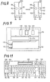
- the standard keyboarad 14C employs a printed-circuit board 110 on which are formed multiple pairs of stationary contacts 112.
- Fig. 9 shows the stationary contacts 112 for- the IMPACT key 90 and the LINE key 94, by way of example. These stationary contacts 112 are connected to a CPU board 116 by a connector 114.
- a plurality of lead wires connecting the stationary contacts 112 and the connector 114 are shown as a single line, in the interest of simplification.
- IC 118 constituting a central processing unit (CPU)
- IC 120 constituting a program memory (ROM)
- IC 122 constituting a working memory (RAM).
- These ICs 118, 120 and 122 correspond to the CPU 30, program memory 32 and working memory 34 of the preceding embodiment.
- the ROM IC 120 is connected to the CPU board 116 by means of a connector socket 124, and is replaceable with another ROM IC 120a which will be described.
- the ROM IC 120 stores control programs similar to those stored in the program memory 32 of Fig. 4.
- the ROM IC 120 stores a key-scanning program as shown in the flow chart of Fig. 10, which is similar to steps S4-S7 of the standard-key scanning routine of Fig. 6 of the preceding embodiment.
- the optional function keys such as the START key 66, STEP STOP key 68, and TEXT PAGE key 70 are added at the right-hand side end section of the standard keyboard 14C, as shown in Fig. 11, in the same manner as described in connection with the preceding embodiment.
- a liquid crystal display 132, an IMPACT switch 134 and a KEYBOARD switch 136 are provided in an upper part of the keyboard 14C.
- the IMPACT switch 134 and the KEYBOARD switch 136 have the same functions as the IMPACT key 90 and the KEYBOARD key 92 on the standard keyboard 14C, respectively.
- the keys which serve as the IMPACT and KEYBOARD keys 90, 92 on the standard keyboard 14C are used as an OPERATE key 138 and a MODE key 140, respectively.
- the signals generated from these keys 138, 140 on the delux keyboard 14D are processed or handled as code data signals different from those generated from the IMPACT and KEYBOARD keys 90, 92 provided on the standard keyboard 14C, since the delux keyboard 14D uses an optional ROM IC 120a in place of the standard ROM IC 120 used on the standard keyboard 14C, as described below.
- an indicator panel 142 is fixedly provided over the left-hand side end section of the standard keyboard 14C (indicated at left in Fig.
- the OPERATE and MODE keys 138, 140 are used to provide a plurality of data processing and printing modes. Since these selector keys 138, 140 are more frequently used than the IMPACT and KEYBOARD keys (IMPACT and KEYBOARD switches 134, 136), the keys 138, 140 are disposed in the left-hand side end section of the delux keyboard 14D, which is more easily accessible than the upper part of the keyboard 14D at which the keys 134, 136 are disposed.
- a printed-circuit board 150 for the liquid crystal display 132 is mounted and connected to the CPU board 116 through a connector 152, and the IMPACT and KEYBOARD switches 134, 136 are connected to a connector 154, as shown in Fig. 12.
- the connector 154 is provided in the standard keyboard 14C such that the connector 154 is connected to the connector 114. Accordingly, the IMPACT and KEYBOARD switches 134, 136 are connected to the CPU board 116, As indicated above, the standard ROM IC 120 provided on the CPU board 116 on the standard keyboard 14C is replaced by the optional ROM IC 120a. Thus, the standard keyboard 14C is modified into the delux keyboard 14D.
- the optional ROM IC 120a on the delux keyboard 14D stores a key-scanning program as illustrated in the flow chart of Fig. 13.
- This key-scanning program is identical with the key-scanning program of Fig. 6 used in the preceding embodiment, except for the absence of a step for determining whether the optional keys have been added or not. Hence, no further explanation of the program is deemed necessary.
- the optional keys to be provided on the delux keyboard 14D of the present modified embodiment consist of the function keys provided in the right-hand side end section of the keyboard, and-.the OPERATE and MODE keys 138, 140 which have been used as the IMPACT and KEYBOARD keys 90, 92 on the standard keyboard 14C.
- the key-scanning program is changed so that not only the standard keys but also the newly provided optional keys are scanned. In the present embodiment, therefore, it is not necessary to use separate signal-generating means (such as the switch 41 used in the preceding embodiment) for generating a signal which indicates that the optional keys have been added.
- the liquid crystal display 132 which is not provided on the standard keyboard 14C is provided on the delux keyboard 14D, so that text data entered through the keyboard 14D can be edited, without the keyboard-printer unit 10 being connected to the CRT display 20 of the display unit 12.
- the standard keyboard 14C has a liquid crystal display having a relatively small digit capacity
- the delux keyboard 14D has a liquid crystal display having a relatively large digit capacity.
- the standard keyboard 14C has the necessary wiring for the large-capacity display, so that the substitution of the large-capacity display for the small-capacity display only requires the replacement of the standard ROM IC 120 with the optional ROM IC 120a which includes a control program for the large-capacity display.
- the N-key roll-over method is used even for the function keys which belong to the group of standard keys.
- the function keys may be scanned in the 2-key roll-over method, even if those function keys belong to the standard keys.
Landscapes
- Engineering & Computer Science (AREA)
- General Engineering & Computer Science (AREA)
- Theoretical Computer Science (AREA)
- Human Computer Interaction (AREA)
- Physics & Mathematics (AREA)
- General Physics & Mathematics (AREA)
- Input From Keyboards Or The Like (AREA)
Applications Claiming Priority (2)
| Application Number | Priority Date | Filing Date | Title |
|---|---|---|---|
| JP61166518A JPS6320613A (ja) | 1986-07-15 | 1986-07-15 | キ−ボ−ドにおけるオプシヨンキ−群の付加方法 |
| JP166518/86 | 1986-07-15 |
Publications (3)
| Publication Number | Publication Date |
|---|---|
| EP0259958A2 true EP0259958A2 (fr) | 1988-03-16 |
| EP0259958A3 EP0259958A3 (en) | 1989-09-27 |
| EP0259958B1 EP0259958B1 (fr) | 1993-09-15 |
Family
ID=15832805
Family Applications (1)
| Application Number | Title | Priority Date | Filing Date |
|---|---|---|---|
| EP19870306215 Expired - Lifetime EP0259958B1 (fr) | 1986-07-15 | 1987-07-14 | Appareil électronique avec possibilité d'extension pour l'entrée de données |
Country Status (3)
| Country | Link |
|---|---|
| EP (1) | EP0259958B1 (fr) |
| JP (1) | JPS6320613A (fr) |
| DE (1) | DE3787432D1 (fr) |
Cited By (3)
| Publication number | Priority date | Publication date | Assignee | Title |
|---|---|---|---|---|
| EP0292238A3 (en) * | 1987-05-19 | 1990-02-14 | Brother Kogyo Kabushiki Kaisha | Data input device having switch matrix scanning means |
| US5111364A (en) * | 1989-09-28 | 1992-05-05 | Brother Kogyo Kabushiki Kaisha | Impact resistant layer for a circuit board |
| CN101770286A (zh) * | 2010-03-12 | 2010-07-07 | 东莞市旭田电子有限公司 | 一种计算机键盘 |
Families Citing this family (1)
| Publication number | Priority date | Publication date | Assignee | Title |
|---|---|---|---|---|
| JPH01147431U (fr) * | 1988-03-30 | 1989-10-12 |
Family Cites Families (6)
| Publication number | Priority date | Publication date | Assignee | Title |
|---|---|---|---|---|
| US4385366A (en) * | 1980-09-02 | 1983-05-24 | Texas Instruments Incorporated | Programmable device using selectively connectable memory module to simultaneously define the functional capability and the display associated with input switches |
| JPS58161026A (ja) * | 1982-03-19 | 1983-09-24 | Hitachi Ltd | 入力装置 |
| DE3325409A1 (de) * | 1983-07-14 | 1985-01-31 | Loewe Opta Gmbh, 8640 Kronach | Alphanumerische tastatur |
| JPS6063635A (ja) * | 1983-09-02 | 1985-04-12 | Mitsubishi Electric Corp | 端末装置のコ−ド制御方式 |
| GB2154948B (en) * | 1984-03-01 | 1987-11-25 | Cherry Electrical Prod | Keyboard |
| US4688020A (en) * | 1984-05-14 | 1987-08-18 | United States Data Corporation | Reconfigurable keyboard |
-
1986
- 1986-07-15 JP JP61166518A patent/JPS6320613A/ja active Pending
-
1987
- 1987-07-14 DE DE87306215T patent/DE3787432D1/de not_active Expired - Lifetime
- 1987-07-14 EP EP19870306215 patent/EP0259958B1/fr not_active Expired - Lifetime
Cited By (4)
| Publication number | Priority date | Publication date | Assignee | Title |
|---|---|---|---|---|
| EP0292238A3 (en) * | 1987-05-19 | 1990-02-14 | Brother Kogyo Kabushiki Kaisha | Data input device having switch matrix scanning means |
| US5111364A (en) * | 1989-09-28 | 1992-05-05 | Brother Kogyo Kabushiki Kaisha | Impact resistant layer for a circuit board |
| CN101770286A (zh) * | 2010-03-12 | 2010-07-07 | 东莞市旭田电子有限公司 | 一种计算机键盘 |
| CN101770286B (zh) * | 2010-03-12 | 2013-01-09 | 东莞市旭田电子有限公司 | 一种计算机键盘 |
Also Published As
| Publication number | Publication date |
|---|---|
| JPS6320613A (ja) | 1988-01-28 |
| EP0259958A3 (en) | 1989-09-27 |
| EP0259958B1 (fr) | 1993-09-15 |
| DE3787432D1 (de) | 1993-10-21 |
Similar Documents
| Publication | Publication Date | Title |
|---|---|---|
| US5165014A (en) | Method and system for matching the software command language of a computer with the printer language of a printer | |
| US4847766A (en) | Dictionary typewriter with correction of commonly confused words | |
| US4464070A (en) | Multi-character display controller for text recorder | |
| EP0205767B1 (fr) | Imprimante comportant une mémoire pour polices de caractères | |
| US5060154A (en) | Electronic typewriter or word processor with detection and/or correction of selected phrases | |
| US4912462A (en) | Letter input device for electronic word retrieval device | |
| GB1601411A (en) | Input terminal for a data processing system | |
| EP0365305A2 (fr) | Dispositif de traitement de données | |
| EP0259958B1 (fr) | Appareil électronique avec possibilité d'extension pour l'entrée de données | |
| GB2192744A (en) | A word processor with attribute functions | |
| JPH0671952A (ja) | 印字装置 | |
| US4994968A (en) | Word processing device | |
| EP0169555A2 (fr) | Dispositif d'affichage d'agencement d'une imprimante électronique | |
| GB2231421A (en) | Memory protection | |
| US5288155A (en) | Printer capable of displaying selected font | |
| US4947343A (en) | Document processing system for detecting an overlap in two characters | |
| US4607966A (en) | Electronic typewriter equipped with text memory which saves format data while deleting a line | |
| US5059974A (en) | Method for determining phantom switch condition | |
| US4785312A (en) | Electronic equipment with a printer unit | |
| JPH06337751A (ja) | 入力装置 | |
| EP0117892A1 (fr) | Machine à écrire électronique | |
| EP0031446B1 (fr) | Dispositif de contrôle à visualisation de plusieurs caractères pour enregistreur de texte | |
| US4706078A (en) | Apparatus for displaying the layout of text | |
| US4957377A (en) | Electronic apparatus having a printing function | |
| US4849908A (en) | Word processor with a ruled line display function |
Legal Events
| Date | Code | Title | Description |
|---|---|---|---|
| PUAI | Public reference made under article 153(3) epc to a published international application that has entered the european phase |
Free format text: ORIGINAL CODE: 0009012 |
|
| AK | Designated contracting states |
Kind code of ref document: A2 Designated state(s): DE FR GB IT |
|
| PUAL | Search report despatched |
Free format text: ORIGINAL CODE: 0009013 |
|
| AK | Designated contracting states |
Kind code of ref document: A3 Designated state(s): DE FR GB IT |
|
| 17P | Request for examination filed |
Effective date: 19900320 |
|
| 17Q | First examination report despatched |
Effective date: 19920225 |
|
| GRAA | (expected) grant |
Free format text: ORIGINAL CODE: 0009210 |
|
| AK | Designated contracting states |
Kind code of ref document: B1 Designated state(s): DE FR GB IT |
|
| PG25 | Lapsed in a contracting state [announced via postgrant information from national office to epo] |
Ref country code: IT Free format text: LAPSE BECAUSE OF FAILURE TO SUBMIT A TRANSLATION OF THE DESCRIPTION OR TO PAY THE FEE WITHIN THE PRE;WARNING: LAPSES OF ITALIAN PATENTS WITH EFFECTIVE DATE BEFORE 2007 MAY HAVE OCCURRED AT ANY TIME BEFORE 2007. THE CORRECT EFFECTIVE DATE MAY BE DIFFERENT FROM THE ONE RECORDED.SCRIBED TIME-LIMIT Effective date: 19930915 Ref country code: DE Effective date: 19930915 Ref country code: FR Effective date: 19930915 |
|
| REF | Corresponds to: |
Ref document number: 3787432 Country of ref document: DE Date of ref document: 19931021 |
|
| EN | Fr: translation not filed | ||
| PGFP | Annual fee paid to national office [announced via postgrant information from national office to epo] |
Ref country code: GB Payment date: 19940705 Year of fee payment: 8 |
|
| PLBE | No opposition filed within time limit |
Free format text: ORIGINAL CODE: 0009261 |
|
| STAA | Information on the status of an ep patent application or granted ep patent |
Free format text: STATUS: NO OPPOSITION FILED WITHIN TIME LIMIT |
|
| 26N | No opposition filed | ||
| PG25 | Lapsed in a contracting state [announced via postgrant information from national office to epo] |
Ref country code: GB Effective date: 19950714 |
|
| GBPC | Gb: european patent ceased through non-payment of renewal fee |
Effective date: 19950714 |