EP0260002B1 - Séparation d'air - Google Patents
Séparation d'air Download PDFInfo
- Publication number
- EP0260002B1 EP0260002B1 EP87307388A EP87307388A EP0260002B1 EP 0260002 B1 EP0260002 B1 EP 0260002B1 EP 87307388 A EP87307388 A EP 87307388A EP 87307388 A EP87307388 A EP 87307388A EP 0260002 B1 EP0260002 B1 EP 0260002B1
- Authority
- EP
- European Patent Office
- Prior art keywords
- column
- stream
- liquid
- outlet
- vapour
- Prior art date
- Legal status (The legal status is an assumption and is not a legal conclusion. Google has not performed a legal analysis and makes no representation as to the accuracy of the status listed.)
- Expired - Lifetime
Links
Images


Classifications
-
- F—MECHANICAL ENGINEERING; LIGHTING; HEATING; WEAPONS; BLASTING
- F25—REFRIGERATION OR COOLING; COMBINED HEATING AND REFRIGERATION SYSTEMS; HEAT PUMP SYSTEMS; MANUFACTURE OR STORAGE OF ICE; LIQUEFACTION SOLIDIFICATION OF GASES
- F25J—LIQUEFACTION, SOLIDIFICATION OR SEPARATION OF GASES OR GASEOUS OR LIQUEFIED GASEOUS MIXTURES BY PRESSURE AND COLD TREATMENT OR BY BRINGING THEM INTO THE SUPERCRITICAL STATE
- F25J3/00—Processes or apparatus for separating the constituents of gaseous or liquefied gaseous mixtures involving the use of liquefaction or solidification
- F25J3/02—Processes or apparatus for separating the constituents of gaseous or liquefied gaseous mixtures involving the use of liquefaction or solidification by rectification, i.e. by continuous interchange of heat and material between a vapour stream and a liquid stream
- F25J3/04—Processes or apparatus for separating the constituents of gaseous or liquefied gaseous mixtures involving the use of liquefaction or solidification by rectification, i.e. by continuous interchange of heat and material between a vapour stream and a liquid stream for air
- F25J3/04248—Generation of cold for compensating heat leaks or liquid production, e.g. by Joule-Thompson expansion
- F25J3/04284—Generation of cold for compensating heat leaks or liquid production, e.g. by Joule-Thompson expansion using internal refrigeration by open-loop gas work expansion, e.g. of intermediate or oxygen enriched (waste-)streams
- F25J3/0429—Generation of cold for compensating heat leaks or liquid production, e.g. by Joule-Thompson expansion using internal refrigeration by open-loop gas work expansion, e.g. of intermediate or oxygen enriched (waste-)streams of feed air, e.g. used as waste or product air or expanded into an auxiliary column
-
- F—MECHANICAL ENGINEERING; LIGHTING; HEATING; WEAPONS; BLASTING
- F25—REFRIGERATION OR COOLING; COMBINED HEATING AND REFRIGERATION SYSTEMS; HEAT PUMP SYSTEMS; MANUFACTURE OR STORAGE OF ICE; LIQUEFACTION SOLIDIFICATION OF GASES
- F25J—LIQUEFACTION, SOLIDIFICATION OR SEPARATION OF GASES OR GASEOUS OR LIQUEFIED GASEOUS MIXTURES BY PRESSURE AND COLD TREATMENT OR BY BRINGING THEM INTO THE SUPERCRITICAL STATE
- F25J3/00—Processes or apparatus for separating the constituents of gaseous or liquefied gaseous mixtures involving the use of liquefaction or solidification
- F25J3/02—Processes or apparatus for separating the constituents of gaseous or liquefied gaseous mixtures involving the use of liquefaction or solidification by rectification, i.e. by continuous interchange of heat and material between a vapour stream and a liquid stream
- F25J3/04—Processes or apparatus for separating the constituents of gaseous or liquefied gaseous mixtures involving the use of liquefaction or solidification by rectification, i.e. by continuous interchange of heat and material between a vapour stream and a liquid stream for air
- F25J3/04151—Purification and (pre-)cooling of the feed air; recuperative heat-exchange with product streams
- F25J3/04187—Cooling of the purified feed air by recuperative heat-exchange; Heat-exchange with product streams
- F25J3/04193—Division of the main heat exchange line in consecutive sections having different functions
-
- F—MECHANICAL ENGINEERING; LIGHTING; HEATING; WEAPONS; BLASTING
- F25—REFRIGERATION OR COOLING; COMBINED HEATING AND REFRIGERATION SYSTEMS; HEAT PUMP SYSTEMS; MANUFACTURE OR STORAGE OF ICE; LIQUEFACTION SOLIDIFICATION OF GASES
- F25J—LIQUEFACTION, SOLIDIFICATION OR SEPARATION OF GASES OR GASEOUS OR LIQUEFIED GASEOUS MIXTURES BY PRESSURE AND COLD TREATMENT OR BY BRINGING THEM INTO THE SUPERCRITICAL STATE
- F25J3/00—Processes or apparatus for separating the constituents of gaseous or liquefied gaseous mixtures involving the use of liquefaction or solidification
- F25J3/02—Processes or apparatus for separating the constituents of gaseous or liquefied gaseous mixtures involving the use of liquefaction or solidification by rectification, i.e. by continuous interchange of heat and material between a vapour stream and a liquid stream
- F25J3/04—Processes or apparatus for separating the constituents of gaseous or liquefied gaseous mixtures involving the use of liquefaction or solidification by rectification, i.e. by continuous interchange of heat and material between a vapour stream and a liquid stream for air
- F25J3/04248—Generation of cold for compensating heat leaks or liquid production, e.g. by Joule-Thompson expansion
- F25J3/04284—Generation of cold for compensating heat leaks or liquid production, e.g. by Joule-Thompson expansion using internal refrigeration by open-loop gas work expansion, e.g. of intermediate or oxygen enriched (waste-)streams
- F25J3/0429—Generation of cold for compensating heat leaks or liquid production, e.g. by Joule-Thompson expansion using internal refrigeration by open-loop gas work expansion, e.g. of intermediate or oxygen enriched (waste-)streams of feed air, e.g. used as waste or product air or expanded into an auxiliary column
- F25J3/04303—Lachmann expansion, i.e. expanded into oxygen producing or low pressure column
-
- F—MECHANICAL ENGINEERING; LIGHTING; HEATING; WEAPONS; BLASTING
- F25—REFRIGERATION OR COOLING; COMBINED HEATING AND REFRIGERATION SYSTEMS; HEAT PUMP SYSTEMS; MANUFACTURE OR STORAGE OF ICE; LIQUEFACTION SOLIDIFICATION OF GASES
- F25J—LIQUEFACTION, SOLIDIFICATION OR SEPARATION OF GASES OR GASEOUS OR LIQUEFIED GASEOUS MIXTURES BY PRESSURE AND COLD TREATMENT OR BY BRINGING THEM INTO THE SUPERCRITICAL STATE
- F25J3/00—Processes or apparatus for separating the constituents of gaseous or liquefied gaseous mixtures involving the use of liquefaction or solidification
- F25J3/02—Processes or apparatus for separating the constituents of gaseous or liquefied gaseous mixtures involving the use of liquefaction or solidification by rectification, i.e. by continuous interchange of heat and material between a vapour stream and a liquid stream
- F25J3/04—Processes or apparatus for separating the constituents of gaseous or liquefied gaseous mixtures involving the use of liquefaction or solidification by rectification, i.e. by continuous interchange of heat and material between a vapour stream and a liquid stream for air
- F25J3/04248—Generation of cold for compensating heat leaks or liquid production, e.g. by Joule-Thompson expansion
- F25J3/04375—Details relating to the work expansion, e.g. process parameter etc.
- F25J3/04393—Details relating to the work expansion, e.g. process parameter etc. using multiple or multistage gas work expansion
-
- F—MECHANICAL ENGINEERING; LIGHTING; HEATING; WEAPONS; BLASTING
- F25—REFRIGERATION OR COOLING; COMBINED HEATING AND REFRIGERATION SYSTEMS; HEAT PUMP SYSTEMS; MANUFACTURE OR STORAGE OF ICE; LIQUEFACTION SOLIDIFICATION OF GASES
- F25J—LIQUEFACTION, SOLIDIFICATION OR SEPARATION OF GASES OR GASEOUS OR LIQUEFIED GASEOUS MIXTURES BY PRESSURE AND COLD TREATMENT OR BY BRINGING THEM INTO THE SUPERCRITICAL STATE
- F25J3/00—Processes or apparatus for separating the constituents of gaseous or liquefied gaseous mixtures involving the use of liquefaction or solidification
- F25J3/02—Processes or apparatus for separating the constituents of gaseous or liquefied gaseous mixtures involving the use of liquefaction or solidification by rectification, i.e. by continuous interchange of heat and material between a vapour stream and a liquid stream
- F25J3/04—Processes or apparatus for separating the constituents of gaseous or liquefied gaseous mixtures involving the use of liquefaction or solidification by rectification, i.e. by continuous interchange of heat and material between a vapour stream and a liquid stream for air
- F25J3/04406—Processes or apparatus for separating the constituents of gaseous or liquefied gaseous mixtures involving the use of liquefaction or solidification by rectification, i.e. by continuous interchange of heat and material between a vapour stream and a liquid stream for air using a dual pressure main column system
- F25J3/04412—Processes or apparatus for separating the constituents of gaseous or liquefied gaseous mixtures involving the use of liquefaction or solidification by rectification, i.e. by continuous interchange of heat and material between a vapour stream and a liquid stream for air using a dual pressure main column system in a classical double column flowsheet, i.e. with thermal coupling by a main reboiler-condenser in the bottom of low pressure respectively top of high pressure column
-
- F—MECHANICAL ENGINEERING; LIGHTING; HEATING; WEAPONS; BLASTING
- F25—REFRIGERATION OR COOLING; COMBINED HEATING AND REFRIGERATION SYSTEMS; HEAT PUMP SYSTEMS; MANUFACTURE OR STORAGE OF ICE; LIQUEFACTION SOLIDIFICATION OF GASES
- F25J—LIQUEFACTION, SOLIDIFICATION OR SEPARATION OF GASES OR GASEOUS OR LIQUEFIED GASEOUS MIXTURES BY PRESSURE AND COLD TREATMENT OR BY BRINGING THEM INTO THE SUPERCRITICAL STATE
- F25J3/00—Processes or apparatus for separating the constituents of gaseous or liquefied gaseous mixtures involving the use of liquefaction or solidification
- F25J3/02—Processes or apparatus for separating the constituents of gaseous or liquefied gaseous mixtures involving the use of liquefaction or solidification by rectification, i.e. by continuous interchange of heat and material between a vapour stream and a liquid stream
- F25J3/04—Processes or apparatus for separating the constituents of gaseous or liquefied gaseous mixtures involving the use of liquefaction or solidification by rectification, i.e. by continuous interchange of heat and material between a vapour stream and a liquid stream for air
- F25J3/04642—Recovering noble gases from air
- F25J3/04648—Recovering noble gases from air argon
- F25J3/04654—Producing crude argon in a crude argon column
- F25J3/04666—Producing crude argon in a crude argon column as a parallel working rectification column of the low pressure column in a dual pressure main column system
- F25J3/04672—Producing crude argon in a crude argon column as a parallel working rectification column of the low pressure column in a dual pressure main column system having a top condenser
- F25J3/04678—Producing crude argon in a crude argon column as a parallel working rectification column of the low pressure column in a dual pressure main column system having a top condenser cooled by oxygen enriched liquid from high pressure column bottoms
-
- F—MECHANICAL ENGINEERING; LIGHTING; HEATING; WEAPONS; BLASTING
- F25—REFRIGERATION OR COOLING; COMBINED HEATING AND REFRIGERATION SYSTEMS; HEAT PUMP SYSTEMS; MANUFACTURE OR STORAGE OF ICE; LIQUEFACTION SOLIDIFICATION OF GASES
- F25J—LIQUEFACTION, SOLIDIFICATION OR SEPARATION OF GASES OR GASEOUS OR LIQUEFIED GASEOUS MIXTURES BY PRESSURE AND COLD TREATMENT OR BY BRINGING THEM INTO THE SUPERCRITICAL STATE
- F25J3/00—Processes or apparatus for separating the constituents of gaseous or liquefied gaseous mixtures involving the use of liquefaction or solidification
- F25J3/02—Processes or apparatus for separating the constituents of gaseous or liquefied gaseous mixtures involving the use of liquefaction or solidification by rectification, i.e. by continuous interchange of heat and material between a vapour stream and a liquid stream
- F25J3/04—Processes or apparatus for separating the constituents of gaseous or liquefied gaseous mixtures involving the use of liquefaction or solidification by rectification, i.e. by continuous interchange of heat and material between a vapour stream and a liquid stream for air
- F25J3/04642—Recovering noble gases from air
- F25J3/04648—Recovering noble gases from air argon
- F25J3/04654—Producing crude argon in a crude argon column
- F25J3/04666—Producing crude argon in a crude argon column as a parallel working rectification column of the low pressure column in a dual pressure main column system
- F25J3/04672—Producing crude argon in a crude argon column as a parallel working rectification column of the low pressure column in a dual pressure main column system having a top condenser
- F25J3/0469—Producing crude argon in a crude argon column as a parallel working rectification column of the low pressure column in a dual pressure main column system having a top condenser and an intermediate re-boiler/condenser
-
- F—MECHANICAL ENGINEERING; LIGHTING; HEATING; WEAPONS; BLASTING
- F25—REFRIGERATION OR COOLING; COMBINED HEATING AND REFRIGERATION SYSTEMS; HEAT PUMP SYSTEMS; MANUFACTURE OR STORAGE OF ICE; LIQUEFACTION SOLIDIFICATION OF GASES
- F25J—LIQUEFACTION, SOLIDIFICATION OR SEPARATION OF GASES OR GASEOUS OR LIQUEFIED GASEOUS MIXTURES BY PRESSURE AND COLD TREATMENT OR BY BRINGING THEM INTO THE SUPERCRITICAL STATE
- F25J2200/00—Processes or apparatus using separation by rectification
- F25J2200/50—Processes or apparatus using separation by rectification using multiple (re-)boiler-condensers at different heights of the column
- F25J2200/52—Processes or apparatus using separation by rectification using multiple (re-)boiler-condensers at different heights of the column in the high pressure column of a double pressure main column system
-
- F—MECHANICAL ENGINEERING; LIGHTING; HEATING; WEAPONS; BLASTING
- F25—REFRIGERATION OR COOLING; COMBINED HEATING AND REFRIGERATION SYSTEMS; HEAT PUMP SYSTEMS; MANUFACTURE OR STORAGE OF ICE; LIQUEFACTION SOLIDIFICATION OF GASES
- F25J—LIQUEFACTION, SOLIDIFICATION OR SEPARATION OF GASES OR GASEOUS OR LIQUEFIED GASEOUS MIXTURES BY PRESSURE AND COLD TREATMENT OR BY BRINGING THEM INTO THE SUPERCRITICAL STATE
- F25J2200/00—Processes or apparatus using separation by rectification
- F25J2200/50—Processes or apparatus using separation by rectification using multiple (re-)boiler-condensers at different heights of the column
- F25J2200/54—Processes or apparatus using separation by rectification using multiple (re-)boiler-condensers at different heights of the column in the low pressure column of a double pressure main column system
-
- F—MECHANICAL ENGINEERING; LIGHTING; HEATING; WEAPONS; BLASTING
- F25—REFRIGERATION OR COOLING; COMBINED HEATING AND REFRIGERATION SYSTEMS; HEAT PUMP SYSTEMS; MANUFACTURE OR STORAGE OF ICE; LIQUEFACTION SOLIDIFICATION OF GASES
- F25J—LIQUEFACTION, SOLIDIFICATION OR SEPARATION OF GASES OR GASEOUS OR LIQUEFIED GASEOUS MIXTURES BY PRESSURE AND COLD TREATMENT OR BY BRINGING THEM INTO THE SUPERCRITICAL STATE
- F25J2245/00—Processes or apparatus involving steps for recycling of process streams
- F25J2245/40—Processes or apparatus involving steps for recycling of process streams the recycled stream being air
-
- F—MECHANICAL ENGINEERING; LIGHTING; HEATING; WEAPONS; BLASTING
- F25—REFRIGERATION OR COOLING; COMBINED HEATING AND REFRIGERATION SYSTEMS; HEAT PUMP SYSTEMS; MANUFACTURE OR STORAGE OF ICE; LIQUEFACTION SOLIDIFICATION OF GASES
- F25J—LIQUEFACTION, SOLIDIFICATION OR SEPARATION OF GASES OR GASEOUS OR LIQUEFIED GASEOUS MIXTURES BY PRESSURE AND COLD TREATMENT OR BY BRINGING THEM INTO THE SUPERCRITICAL STATE
- F25J2290/00—Other details not covered by groups F25J2200/00 - F25J2280/00
- F25J2290/10—Mathematical formulae, modeling, plot or curves; Design methods
-
- Y—GENERAL TAGGING OF NEW TECHNOLOGICAL DEVELOPMENTS; GENERAL TAGGING OF CROSS-SECTIONAL TECHNOLOGIES SPANNING OVER SEVERAL SECTIONS OF THE IPC; TECHNICAL SUBJECTS COVERED BY FORMER USPC CROSS-REFERENCE ART COLLECTIONS [XRACs] AND DIGESTS
- Y10—TECHNICAL SUBJECTS COVERED BY FORMER USPC
- Y10S—TECHNICAL SUBJECTS COVERED BY FORMER USPC CROSS-REFERENCE ART COLLECTIONS [XRACs] AND DIGESTS
- Y10S62/00—Refrigeration
- Y10S62/923—Inert gas
- Y10S62/924—Argon
Definitions
- This invention relates to air separation.
- One distilling system comprises a first column having a rectifying section in which there are varying amounts of reflux, and a second column having a stripping section in which there are varying amounts of reboil.
- Thermal linkage between the two columns is provided by taking vapour from the variable reflux column, partially condensing it in the stripping column, and returning the resulting liquid-vapour mixture to the variable reflux column.
- the partial condensation takes place in passages formed in distillation trays of the stripping column. Heat is thus extracted from the stripping column and is transferred to the variable reflux column.
- WO 86/06462 discloses the use of an 'intermediate' reboil step using an argon-enriched stream from an argon column as the heat exchange medium, but returns the reboiled liquid to the same mass-transfer stage as that from which the liquid is taken thereby introducing inefficiency into the distillation process.
- a method of separating air comprising fractionating air in a first distillation column, providing reboil at a bottom region and reflux at a top region of the first distillation column, withdrawing a product oxygen stream from a bottom region of the column, withdrawing a nitrogen stream from a top region of the column, withdrawing a stream enriched in argon from an intermediate level in the column, and separating it in a second distillation column to form a product argon stream, wherein at least one liquid stream having a composition intermediate the extremes of composition that occur in the first column is taken from the first column and is at least partially boiled externally to the first distillation column by heat exchange with fluid taken from the second distillation column, resulting boiled liquid is returned to said first distillation column, and said fluid is returned to the second distillation column, wherein the said resulting boiled liquid is returned to said first distillation at a different level from the one from which the said liquid stream is taken, said different level being where the composition of the vapour closely matches that
- the invention also provides apparatus for separating air, comprising a first distillation column, means for introducing air into the column, means for providing reboil at a bottom region of the column, means for providing reflux to a top region of the column, a first outlet from a bottom region of the column for the withdrawal of an oxygen product stream, a second outlet from top region of the column for the withdrawal of nitrogen, and a third outlet from an intermediate level of the column for the withdrawal of a stream enriched in argon, said third outlet communicating with a second distillation column for separating an argon product from said stream relatively rich in argon, wherein the first column has a fourth outlet for the withdrawal from the first column of at least one liquid stream of composition intermediate the extremes of composition that occur in the first column, and there is provided heat exchange means having a first pass communicating at one of its ends with said fourth outlet and at its other end with an inlet to said first column, and a second pass communicating at one of its ends with an outlet from said second column and at its other end with an inlet to said second
- the fluid taken from the second column is preferably a vapour, which is desirably at least partially condensed by heat exchange with the liquid stream of intermediate composition.
- the heat exchange means thus functions as a reboiler condenser.
- the first column is preferably the lower pressure column of a double column system.
- the composition of the boiled stream matches more closely the composition of the vapour to which it is returned than the vapour in mass-exchange relationship with the liquid from which it is taken. In general, it is desirable for this reason that the composition of the boiled steam matches closely the composition of the vapour into which it is introduced on being returned to the first column.
- the liquid stream of intermediate composition includes 40 to 60% by volume of oxygen.
- the heat exchange between the liquid stream of intermediate composition and the heat exchange fluid be effective to boil all the steam.
- the resulting liquid-vapour bi-phase may be separated into liquid and vapour, and a stream of the boiled fluid returned to the first column in accordance with the invention.
- the remaining liquid is desirably passed into liquid of a similar composition in a column forming part of the apparatus according to the invention (and typically the first column).
- it may be subjected to further heat exchange in order to complete the phase change.
- the vapour produced as a result of such further heat exchange has a different composition from that of the vapour produced as a result of the first heat exchange.
- liquid-vapour contact column typically the first column
- vapour having a similar composition to said vapour produced as a result of further heat exchange.
- the or each liquid stream of intermediate composition taken from a chosen level for reboiling comprises from 20 to 50% by volumne of the liquid flow at that level.
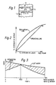
- FIG. 1 of the drawings there are shown two communicating trays (n-i) and n of a distillation column. On these two trays mass exchange takes place between liquid and vapour.
- Figure 1 shows vapour V1 and liquid L1 passing out of mass exchange relationship with one another from tray n.
- Liquid L1 flows through the downcomer onto tray (n-i) where it comes into contact with vapour ascending from the tray below tray (n-i).
- a liquid L2 leaves the tray (n-i) and a vapour V2 ascends to tray n.
- the vapour V1 in the context of this specification we refer to the vapour V1 as "corresponding" with the liquid L1.
- V1 is in equilibrium with L1 and V2 is in equilibrium with L2.
- the total amount of irreversible work (ignoring pressure drop) done in operating the column shown in Figure 1 is represented by the cross-hatched area in Figure 3.
- the area of the graph below the cross-hatched area represents the reversible work of separating oxygen from nitrogen.
- the abscissa in Figure 3 can be plotted in terms of the liquid phase, or the vapour phase, or both.
- the operating line can be "lifted" at the level of tray n back to near the equilibrium line.
- Part A ⁇ B ⁇ of the line passes through the origin as a pure oxygen product is obtained at the bottom of the column. Since providing extra heat at the level of the tray n does not change the mass flux on that part of the column, the slope of the other part C ⁇ D ⁇ is such that if it were extended downwards it would also pass through the origin. The result therefore of providing heat at the level of tray n is that the irreversible work of mixing in that part of the column below tray n is reduced while that above tray n remains unaltered. This fact is illustrated in Figure 5 in which the cross- hatched area should be compared with the corresponding area in Figure 3.
- a further reduction in the irreversible work can be achieved by withdrawing a stream of liquid of intermediate composition from a tray n, reboiling it externally of the column, and returning the reboiled stream to the column at a level (tray m) where the composition of the vapour is substantially the same as that of the reboiled stream.
- vapour stream formed by intermediate reboil is divided, with one part of it being returned to the column at one such position and the remainder being returned at one or more other such positions.
- Each of these "matching" positions results in there being a relatively close proximity between the point B ⁇ in Figure 6, and the equilibrium line, and therefore, if selected for the returning reboiled liquid, makes it possible to keep down the amount of irreversible work of mixing that needs to be done.
- the position for such return is desirably selected so as to minimise the irreversible work that is done in the column. Irreversible work of mixing is not the sole source of such irreversible or lost work; there are also losses arising out of pressure drop in the column.
- argon constitutes less than 1% by volume of air, its presence in the oxygen-nitrogen mixture does to some extent affect the amount of lost work that can be saved in accordance with the invention and the composition of the stream selected for intermediate reboil.
- the selection of the level in the column at which the reboiled liquid stream is returned is also influenced by the desirability of maximising the yield of argon. Indeed, in some instances, this criterion may take priority over the other criteria affecting the selection of the return position.
- the closeness of matching may be assessed by calculating the work involved in mixing the respective fluids, the less the calculated work, the closer the match.
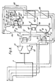
- an air stream at a pressure of about 6.5 atmospheres (absolute) is passed at a temperature of about 300K into the warm end of a reversing heat exchanger 2 and leaves the cold end of the reversing heat exchanger 2 at a temperature of about 103K.
- the air then passes into the higher pressure column 6 of a double column system, indicated generally by the reference number 4, through an inlet 10 below the level of the lowest tray in the column.
- a stream of air is immediately withdrawn from the column 6 through an outlet 12.
- One portion of this stream is returned to the cold end of the reversing heat exchanger 2. This portion of the air stream flows through the heat exchanger 2 countercurrently to the incomming air stream.
- the portion is then withdrawn from an intermediate location of the heat exchanger at a temperature of about 157 K and is divided into two streams.
- One of the streams is expanded in expansion turbine 14 to a pressure of about 1.21 atmospheres.
- the expanded air leaves the turbine 14 at a temperature of about 107 K and is mixed with an impure or waste nitrogen stream from the low pressure column 8 of a double column system 4.
- the resulting mixture is then introduced into a heat exchanger 16, which it leaves at a temperature of about 101K and then flows back through the reversing heat exchanger from the cold end to the warm end thereof, and is then vented to the atmosphere.
- the air for the turbine 14 may be taken directly from the incoming air flow at an intermediate region of the heat exchanger 2.
- the second stream of air that is formed by dividing the air leaving the heat exchanger 2 at an intermediate temperature is expanded to a pressure of about 1.42 atmospheres in expansion turbine 18. This air leaves the expansion turbine 18 in a superheated state at a temperature of 111 K and is introduced into the lower pressure column 8 through an inlet 20.
- the second portion of this air is reboiled and returned to the column 6 through inlet 22.
- One part of this portion of the air is condensed in a heat exchanger 24, and the other part is condensed in the heat exchanger 16, the other part flowing through the heat exchanger 16 countercurrently to the mixture of air and waste nitrogen.
- the air is separated at a pressure of about 6 atmospheres into an oxygen-rich liquid and a nitrogen liquid fraction.
- the oxygen-rich liquid is used as the main feed for the lower pressure column 8 which is employed to separate the liquid to produce a substantially pure oxygen product, a substantially pure nitrogen product, an argon-enriched air stream which is separated in a further column 40 operating at substantially the same pressure as the lower pressure column 8 to form a substantially pure argon product.
- the oxygen-rich liquid is withdrawn from the bottom of the column 6 through an outlet 26. It is then sub-cooled in a heat exchanger 28 which it enters as temperature of about 102 K. One part of the sub-cooled liquid is passed through a throttling valve 30 and is then introduced into the low pressure column 8 through an inlet 32.
- the other part of the sub-cooled liquid is passed through a throttling valve 34, and then as a liquid-vapour biphase enters a condenser 36 associated with the argon column 40.
- the stream of liquid-vapour mixture entering the condenser 36 provides cooling for the condenser, and after leaving the condenser 36 enters the column 8 as vapour through an inlet 38 positioned below the level of the inlet 32.
- Nitrogen rising to the top of the column 6 enters a condenser -reboiler 42 that provides a thermal link between the columns 6 and 8 of the double column system 4.
- the nitrogen vapour is condensed against a flow of liquid oxygen from the bottom of the column 8 and part of the resulting condensed nitrogen is employed as reflux for the column 6.
- the remainder of the condensed nitrogen is withdrawn from the column 6 through an outlet 44 at a temperature of about 97 K and sub-cooling it to a temperature of about 81 K by heat exchange in a heat exchanger 46.
- Sub-cooled liquid nitrogen is then passed through a throttling valve 48 and is introduced into the top of the column 8 through an inlet 50.
- the liquid nitrogen introduced into the top of the column 8 through the inlet 50 serves as reflux for the column 8.
- the liquid becomes progressively richer in oxygen as it descends the column 8, and the ascending vapour stream becomes progressively richer in nitrogen.
- Reboil for the column 8 is provided as aforesaid by the condenser - reboiler 42.
- a portion of the reboiled oxygen is withdrawn from the bottom of the column 8 at a temperature of about 95 K through an outlet 52 and is warmed to a temperature of about 101 K by flow through the heat exchanger 24 countercurrently to the air flow through that heat exchanger.
- This product oxygen stream is thereby warmed to a temperature of about 102 K and is then passed through the heat exchanger 2 countercurrently to the incoming flow of air the oxygen product stream, which is typically 99.8% pure, leaves the warm end of the heat exchanger 2 at a temperature of about 297 K.
- a gaseous nitrogen product stream is taken from the top of the lower pressure column 8 through an outlet 54 at a temperature of about 79 K and a pressure of about 1.25 atmospheres.
- the nitrogen product stream is first warmed in heat exchanger 46, flowing countercurrently to the nitrogen stream taken from the condenser reboiler 42. It leaves the heat exchanger 46 and is then warmed by passage through the heat exchanger 28 countercurrently to the oxygen-enriched liquid stream taken from the column 6 via the outlet 26.
- the product nitrogen stream is further warmed to about 101 K by passage through the heat exchanger 16 cocurrently with the mixture of expanded air and waste nitrogen.
- the product nitrogen stream then enters the reversing heat exchanger 2 and flows therethrough countercurrently to the incoming air flow, leaving the heat exchanger 2 at a temperature of about 290 K.
- impure nitrogen typically containing about 50 volumes per million by volume of oxygen is withdrawn from the column 8 at a level a few trays below the uppermost tray in that column but above the level of the inlet 32.
- the waste nitrogen stream is withdrawn at a temperature of about 79K through an outlet 56 and is then passed through the heat exchangers 46 and 28 cocurrently with the product nitrogen stream. It is then united with the expanded air stream from the turbine 14 and passed through the heat exchangers 16 and 2 as hereinbefore described.
- Sufficient reflux is provided in the column 8 to ensure that there is a local maximum of argon in the vapour phase at a level of the column intermediate its top and bottom.
- a stream of vapour is withdrawn through an outlet 58 and passed to the column 40 entering it at level below the bottom tray thereof through an inlet 60.
- the argon-enriched stream is fractionated to provide argon product at the top of the column.
- Argon vapour reaching the top of the column is condensed in condenser 36 and a part of the resulting liquid argon is withdrawn through outlet 62 as liquid product, another part being used as the reflux for the column 40.
- Oxygen-rich liquid collects at the bottom of column 40 and is withdrawn therefrom through an outlet 64 and returned to the column 8 through an inlet 66 at a level below that of the outlet 58.
- the efficiency with which the column 8 operates is enhanced by a withdrawal of a liquid stream containing about 50% by volume of oxygen from the column 8 through an outlet 70 at a level below that of the inlet 38 and above that of the outlet 58.
- the liquid stream is totally reboiled in a heat exchanger 72 and is returned to the column 8 through inlet 74 at a level below that of the outlet 70 but above that of the outlet 58 where the vapour matches closely with the composition of the reboiled liquid.
- the heating for the heat exchanger 72 is provided by passing a stream of oxygen-rich vapour (containing more than 65% by volume of oxygen) from the argon side column 40 through the heat exchanger 72 countercurrently to the stream that is reboiled therein.
- the stream withdrawn from the argon column 40 through the outlet 75 is typically condensed in the heat exchanger 72, and the resulting liquid is returned to the column through an inlet 76.
- Reboiling of the stream taken from the outlet 70 of the column 8 renders the operation of the column 8 more thermodynamically efficient for the reasons discussed herein with reference to Figures 1 to 7. It is therefore possible to enhance the production of the plant illustrated in Figure 8 by introduction of the expanded air stream into a low pressure column through the inlet 20. Typically, about 5 to 6% of the net air flow to the columns is expanded in the turbine 18 and a similar quantity of air is expanded in the turbine 14.
- the plant may be provided with preliminary beds of molecular sieve of a kind that preferentially adsorbs carbon dioxide and water vapour from the incoming air.
- the construction and operation of apparatus employing beds of molecular sieve to remove water vapour and carbon dioxide from the incoming air are well known in the air separation art and need not be further described herein.
Landscapes
- Engineering & Computer Science (AREA)
- Physics & Mathematics (AREA)
- Mechanical Engineering (AREA)
- Thermal Sciences (AREA)
- General Engineering & Computer Science (AREA)
- Separation By Low-Temperature Treatments (AREA)
Claims (16)
- Procédé pour séparer les constituants de l'air, comprenant le fractionnement de l'air dans une première colonne de distillation, la réalisation d'un rebouillage dans une région inférieure et d'un reflux dans une région supérieure de la première colonne de distillation, le soutirage d'un courant d'oxygène produit prélevé sur une région basse de la colonne, le soutirage d'un courant d'azote d'une région supérieure de la colonne, le soutirage d'un courant enrichi en argon prélevé à un niveau intermédiaire de la colonne, et la séparation de ce courant, dans une seconde colonne de distillation, pour former un courant d'argon comme produit, procédé dans lequel au moins un courant de liquide, ayant une composition intermédiaire entre les extrêmes de composition se produisant dans la première colonne, est prélevé de la première colonne, est au moins partiellement soumis à ébullition à l'extérieur de la première colonne de distillation, par échange de chaleur avec du fluide prélevé sur la seconde colonne de distillation, ce qui donne un liquide ayant bouilli que l'on renvoie vers ladite première colonne de distillation, et ledit fluide est renvoyé vers la seconde colonne de distillation, procédé caractérisé en ce que ledit liquide résultant, ayant bouilli, est renvoyé vers ladite première colonne de distillation à un niveau différent de celui où ledit courant liquide est prélevé, ledit niveau différent étant celui où la composition de la vapeur correspond étroitement à la composition du liquide résultant ayant bouilli.
- Procédé tel que revendiqué à la revendication 1, dans lequel ledit fluide est une vapeur, qui est au moins partiellement condensée par échange de chaleur avec le courant de liquide de composition intermédiaire.
- Procédé tel que revendiqué à la revendication 1 ou à la revendication 2, dans lequel la première colonne est une colonne à basse pression faisant partie d'un système à deux colonnes comprenant la colonne à basse pression et une colonne à pression supérieure ou haute pression.
- Procédé tel que revendiqué à la revendication 3, dans lequel de l'air est introduit dans lesdites colonnes à haute et à basse pression.
- Procédé tel que revendiqué à la revendication 4, dans lequel l'air, qui est introduit dans la colonne à basse pression, est détendu, de la pression de fonctionnement de la colonne à haute pression jusqu'à une pression convenant pour son introduction dans la colonne à basse pression.
- Procédé tel que revendiqué dans l'une quelconque des revendications précédentes, dans lequel on produit également un courant d'azote comme produit et un courant d'azote comme déchet ou courant résiduaire.
- Procédé tel que revendiqué dans l'une quelconque des revendications précédentes, dans lequel le courant liquide à composition intermédiaire comprend de 40 à 60 % en volume d'oxygène.
- Procédé tel que revendiqué dans l'une quelconque des revendications précédentes, dans lequel on fait rebouillir une partie seulement du courant liquide de composition intermédiaire.
- Procédé tel que revendiqué à la revendication 8, dans lequel le liquide résiduel est renvoyé vers la première colonne.
- Procédé tel que revendiqué à la revendication 8, dans lequel le liquide résiduel est soumis à une étape supplémentaire d'échange de chaleur et est aussi soumis à réébullition, la vapeur résultante étant renvoyée vers la première colonne de distillation.
- Procédé tel que revendiqué dans l'une quelconque des revendications précédentes, dans lequel le courant de liquide de composition intermédiaire représente de 20 à 50 % du volume du courant liquide en écoulement, au niveau où il est prélevé de la première colonne.
- Appareil pour séparer les constituants de l'air, comprenant une première colonne de distillation, un moyen ou dispositif pour introduire de l'air dans la colonne, un moyen ou dispositif pour assurer une réébullition dans la région inférieure de la colonne, un moyen pour assurer un reflux dirigé vers la région supérieure de la colonne, une première sortie d'une région inférieure de la colonne pour le soutirage d'un courant d'oxygène constituant un produit, une seconde sortie de la région supérieure de la colonne pour le soutirage de l'azote, et une troisième sortie, d'un niveau intermédiaire de la colonne, pour le soutirage d'un courant enrichi en argon, ladite troisième sortie communiquant avec une seconde colonne de distillation pour séparer, dudit courant relativement riche en argon, un produit constitué par de l'argon, appareil dans lequel la première colonne comporte une quatrième sortie pour le soutirage, de la première colonne, d'au moins un courant de liquide, ayant une composition intermédiaire entre les extrêmes de composition se présentant dans la première colonne, et il existe un dispositif pour échange de chaleur ayant un premier conduit communiquant par une de ses extrémités avec ladite quatrième sortie et par son autre extrémité avec une entrée de ladite première colonne, et un second conduit communiquant par une de ses extrémités avec une sortie de ladite seconde colonne et par son autre extrémité avec une entrée de ladite seconde colonne, de sorte qu'en service le courant de liquide à composition intermédiaire peut être au moins partiellement soumis à ébullition par échange de chaleur avec du fluide provenant de la seconde colonne, la vapeur résultante étant renvoyée vers la première colonne de distillation et le fluide provenant de la seconde colonne y étant renvoyé, appareil caractérisé en ce que l'entrée vers ladite première colonne avec laquelle ledit premier conduit communique est à un niveau différent de celui de ladite quatrième sortie, ce niveau étant choisi de façon qu'en service la composition de la vapeur à ce niveau corresponde étroitement à celle de ladite vapeur résultante.
- Appareil tel que revendiqué à la revendication 12, dans lequel ledit dispositif d'échange de chaleur joue également le rôle d'un condenseur pour condenser ledit fluide.
- Appareil tel que revendiqué à la revendication 12 ou à la revendication 13, dans lequel ladite première colonne est la colonne à basse pression d'un système à deux colonnes comprenant des colonnes à haute pression et à basse pression, et le dispositif pour introduire l'air dans la colonne comprend un conduit mettant la colonne à basse pression en communication avec de l'air liquide, enrichi en oxygène, qui se rassemble au bas de la colonne à haute pression.
- Appareil tel que revendiqué à la revendication 14, dans lequel ledit dispositif pour introduire de l'air dans la première colonne comprend en outre une turbine de détente, dont l'entrée communique avec une source d'air sensiblement à la pression de la colonne à haute pression et dont la sortie communique avec une entrée de la colonne à basse pression.
- Appareil tel que revendiqué dans la revendication 14 ou 15, dans lequel ladite seconde sortie est destinée au soutirage d'un courant d'azote constituant un produit, avec présence d'une sortie supplémentaire de la colonne à basse pression pour permettre de soutirer un courant d'azote résiduaire ou impur.
Applications Claiming Priority (2)
| Application Number | Priority Date | Filing Date | Title |
|---|---|---|---|
| GB868622055A GB8622055D0 (en) | 1986-09-12 | 1986-09-12 | Air separation |
| GB8622055 | 1986-09-12 |
Publications (3)
| Publication Number | Publication Date |
|---|---|
| EP0260002A2 EP0260002A2 (fr) | 1988-03-16 |
| EP0260002A3 EP0260002A3 (en) | 1988-11-23 |
| EP0260002B1 true EP0260002B1 (fr) | 1991-09-18 |
Family
ID=10604120
Family Applications (1)
| Application Number | Title | Priority Date | Filing Date |
|---|---|---|---|
| EP87307388A Expired - Lifetime EP0260002B1 (fr) | 1986-09-12 | 1987-08-21 | Séparation d'air |
Country Status (7)
| Country | Link |
|---|---|
| US (1) | US4747859A (fr) |
| EP (1) | EP0260002B1 (fr) |
| AU (1) | AU7832487A (fr) |
| CA (1) | CA1296992C (fr) |
| DE (1) | DE3773095D1 (fr) |
| GB (1) | GB8622055D0 (fr) |
| ZA (1) | ZA876192B (fr) |
Cited By (5)
| Publication number | Priority date | Publication date | Assignee | Title |
|---|---|---|---|---|
| GB2219385A (en) * | 1988-06-02 | 1989-12-06 | Union Carbide Corp | Air separation process and apparatus |
| EP0473078A1 (fr) * | 1990-08-28 | 1992-03-04 | Air Products And Chemicals, Inc. | Récupération ameliorée d'argon à partir des cycles cryogéniques de séparation de l'air |
| US5123249A (en) * | 1990-04-18 | 1992-06-23 | The Boc Group Plc | Air separation |
| EP0684435B2 (fr) † | 1994-05-13 | 2000-03-29 | Praxair Technology, Inc. | Procédé de récupération de l'oxygène à l'acide d'un procédé de séparation d'air cryogénique |
| EP4150275A1 (fr) * | 2020-05-11 | 2023-03-22 | Praxair Technology, Inc. | Système et procédé de récupération d'azote, d'argon, et d'oxygène d'une unité de séparation d'air cryogénique à pression modérée |
Families Citing this family (8)
| Publication number | Priority date | Publication date | Assignee | Title |
|---|---|---|---|---|
| GB8806478D0 (en) * | 1988-03-18 | 1988-04-20 | Boc Group Plc | Air separation |
| FR2650378A1 (fr) * | 1989-07-28 | 1991-02-01 | Air Liquide | Installation de distillation d'air produisant de l'argon |
| US5129932A (en) * | 1990-06-12 | 1992-07-14 | Air Products And Chemicals, Inc. | Cryogenic process for the separation of air to produce moderate pressure nitrogen |
| US5289688A (en) * | 1991-11-15 | 1994-03-01 | Air Products And Chemicals, Inc. | Inter-column heat integration for multi-column distillation system |
| US5230217A (en) * | 1992-05-19 | 1993-07-27 | Air Products And Chemicals, Inc. | Inter-column heat integration for multi-column distillation system |
| US5275004A (en) * | 1992-07-21 | 1994-01-04 | Air Products And Chemicals, Inc. | Consolidated heat exchanger air separation process |
| US20080127676A1 (en) * | 2006-11-30 | 2008-06-05 | Amcscorporation | Method and apparatus for production of high-pressure nitrogen from air by cryogenic distillation |
| CA3063409A1 (fr) | 2017-05-16 | 2018-11-22 | Terrence J. Ebert | Appareil et procede de liquefaction de gaz |
Family Cites Families (16)
| Publication number | Priority date | Publication date | Assignee | Title |
|---|---|---|---|---|
| US2812645A (en) | 1956-02-29 | 1957-11-12 | Union Carbide Corp | Process and apparatus for separating gas mixtures |
| DE1229561B (de) * | 1962-12-21 | 1966-12-01 | Linde Ag | Verfahren und Vorrichtung zum Zerlegen von Luft durch Verfluessigung und Rektifikation mit Hilfe eines Inertgaskreislaufes |
| US3543528A (en) * | 1965-03-11 | 1970-12-01 | Pullman Inc | Separation of low-boiling gas mixtures |
| DE1922956B1 (de) * | 1969-05-06 | 1970-11-26 | Hoechst Ag | Verfahren zur Erzeugung von argonfreiem Sauerstoff durch Rektifikation von Luft |
| DE2202206A1 (de) | 1972-01-18 | 1973-07-26 | Messer Griesheim Gmbh | Verfahren zur zerlegung von gasgemischen durch zweistufige rektifikation |
| GB1508603A (en) | 1974-04-11 | 1978-04-26 | Haselden G | Distillation processes and apparatus |
| JPS56124879A (en) * | 1980-02-26 | 1981-09-30 | Kobe Steel Ltd | Air liquefying and separating method and apparatus |
| US4604116A (en) * | 1982-09-13 | 1986-08-05 | Erickson Donald C | High pressure oxygen pumped LOX rectifier |
| JPS59150286A (ja) * | 1983-02-15 | 1984-08-28 | 日本酸素株式会社 | アルゴンの製造方法 |
| US4605427A (en) * | 1983-03-31 | 1986-08-12 | Erickson Donald C | Cryogenic triple-pressure air separation with LP-to-MP latent-heat-exchange |
| US4533375A (en) * | 1983-08-12 | 1985-08-06 | Erickson Donald C | Cryogenic air separation with cold argon recycle |
| US4578095A (en) * | 1984-08-20 | 1986-03-25 | Erickson Donald C | Low energy high purity oxygen plus argon |
| US4670031A (en) * | 1985-04-29 | 1987-06-02 | Erickson Donald C | Increased argon recovery from air distillation |
| US4615716A (en) * | 1985-08-27 | 1986-10-07 | Air Products And Chemicals, Inc. | Process for producing ultra high purity oxygen |
| US4756731A (en) * | 1986-02-20 | 1988-07-12 | Erickson Donald C | Oxygen and argon by back-pressured distillation |
| US4817393A (en) * | 1986-04-18 | 1989-04-04 | Erickson Donald C | Companded total condensation loxboil air distillation |
-
1986
- 1986-09-12 GB GB868622055A patent/GB8622055D0/en active Pending
-
1987
- 1987-08-20 ZA ZA876192A patent/ZA876192B/xx unknown
- 1987-08-21 DE DE8787307388T patent/DE3773095D1/de not_active Expired - Fee Related
- 1987-08-21 EP EP87307388A patent/EP0260002B1/fr not_active Expired - Lifetime
- 1987-09-10 US US07/095,287 patent/US4747859A/en not_active Expired - Fee Related
- 1987-09-11 CA CA000546664A patent/CA1296992C/fr not_active Expired - Fee Related
- 1987-09-11 AU AU78324/87A patent/AU7832487A/en not_active Abandoned
Cited By (7)
| Publication number | Priority date | Publication date | Assignee | Title |
|---|---|---|---|---|
| GB2219385A (en) * | 1988-06-02 | 1989-12-06 | Union Carbide Corp | Air separation process and apparatus |
| GB2219385B (en) * | 1988-06-02 | 1992-09-16 | Union Carbide Corp | Air separation process and apparatus |
| US5123249A (en) * | 1990-04-18 | 1992-06-23 | The Boc Group Plc | Air separation |
| EP0473078A1 (fr) * | 1990-08-28 | 1992-03-04 | Air Products And Chemicals, Inc. | Récupération ameliorée d'argon à partir des cycles cryogéniques de séparation de l'air |
| EP0684435B2 (fr) † | 1994-05-13 | 2000-03-29 | Praxair Technology, Inc. | Procédé de récupération de l'oxygène à l'acide d'un procédé de séparation d'air cryogénique |
| EP4150275A1 (fr) * | 2020-05-11 | 2023-03-22 | Praxair Technology, Inc. | Système et procédé de récupération d'azote, d'argon, et d'oxygène d'une unité de séparation d'air cryogénique à pression modérée |
| EP4150275B1 (fr) * | 2020-05-11 | 2026-02-11 | Praxair Technology, Inc. | Système et procédé de récupération d'azote, d'argon, et d'oxygène d'une unité de séparation d'air cryogénique à pression modérée |
Also Published As
| Publication number | Publication date |
|---|---|
| EP0260002A3 (en) | 1988-11-23 |
| DE3773095D1 (de) | 1991-10-24 |
| GB8622055D0 (en) | 1986-10-22 |
| EP0260002A2 (fr) | 1988-03-16 |
| US4747859A (en) | 1988-05-31 |
| AU7832487A (en) | 1988-03-17 |
| CA1296992C (fr) | 1992-03-10 |
| ZA876192B (en) | 1989-01-25 |
Similar Documents
| Publication | Publication Date | Title |
|---|---|---|
| US4843828A (en) | Liquid-vapor contact method and apparatus | |
| US5410885A (en) | Cryogenic rectification system for lower pressure operation | |
| EP0633438B2 (fr) | Séparation de l'air | |
| US4790866A (en) | Air separation | |
| US5582035A (en) | Air separation | |
| US6257019B1 (en) | Production of nitrogen | |
| EP0687876B1 (fr) | Séparation de l'air | |
| EP0260002B1 (fr) | Séparation d'air | |
| US5485729A (en) | Air separation | |
| EP1243883A1 (fr) | Séparation d'air | |
| EP0770841B1 (fr) | Séparation d'air | |
| EP0206493B1 (fr) | Separation d'Argon d'un mélange de gaz | |
| US6141989A (en) | Air separation | |
| CA2092454C (fr) | Systeme de rectification cryogenique a taux de recuperation eleve | |
| KR19980018093A (ko) | 저순도 산소와 고순도 산소를 제조하기 위한 저온 정류 시스템 | |
| CA2212773C (fr) | Systeme de rectification cryogene pour produire de l'oxygene de purete plus faible et de l'oxygene de purete plus elevee | |
| EP0333384B1 (fr) | Séparation d'air | |
| US4747860A (en) | Air separation | |
| EP0328239B1 (fr) | Séparation d'air |
Legal Events
| Date | Code | Title | Description |
|---|---|---|---|
| PUAI | Public reference made under article 153(3) epc to a published international application that has entered the european phase |
Free format text: ORIGINAL CODE: 0009012 |
|
| AK | Designated contracting states |
Kind code of ref document: A2 Designated state(s): BE DE FR GB IT NL |
|
| PUAL | Search report despatched |
Free format text: ORIGINAL CODE: 0009013 |
|
| AK | Designated contracting states |
Kind code of ref document: A3 Designated state(s): BE DE FR GB IT NL |
|
| 17P | Request for examination filed |
Effective date: 19890518 |
|
| 17Q | First examination report despatched |
Effective date: 19900117 |
|
| GRAA | (expected) grant |
Free format text: ORIGINAL CODE: 0009210 |
|
| AK | Designated contracting states |
Kind code of ref document: B1 Designated state(s): BE DE FR GB IT NL |
|
| ITF | It: translation for a ep patent filed | ||
| ET | Fr: translation filed | ||
| REF | Corresponds to: |
Ref document number: 3773095 Country of ref document: DE Date of ref document: 19911024 |
|
| PLBI | Opposition filed |
Free format text: ORIGINAL CODE: 0009260 |
|
| 26 | Opposition filed |
Opponent name: AIR PRODUCTS AND CHEMICALS INC. Effective date: 19920619 |
|
| NLR1 | Nl: opposition has been filed with the epo |
Opponent name: AIR PRODUCTS AND CHEMICALS INC. |
|
| PLBN | Opposition rejected |
Free format text: ORIGINAL CODE: 0009273 |
|
| STAA | Information on the status of an ep patent application or granted ep patent |
Free format text: STATUS: OPPOSITION REJECTED |
|
| 27O | Opposition rejected |
Effective date: 19931121 |
|
| NLR2 | Nl: decision of opposition | ||
| PGFP | Annual fee paid to national office [announced via postgrant information from national office to epo] |
Ref country code: FR Payment date: 19950717 Year of fee payment: 9 |
|
| PGFP | Annual fee paid to national office [announced via postgrant information from national office to epo] |
Ref country code: NL Payment date: 19950719 Year of fee payment: 9 |
|
| PGFP | Annual fee paid to national office [announced via postgrant information from national office to epo] |
Ref country code: DE Payment date: 19950725 Year of fee payment: 9 |
|
| PGFP | Annual fee paid to national office [announced via postgrant information from national office to epo] |
Ref country code: GB Payment date: 19950727 Year of fee payment: 9 |
|
| PGFP | Annual fee paid to national office [announced via postgrant information from national office to epo] |
Ref country code: BE Payment date: 19950731 Year of fee payment: 9 |
|
| PG25 | Lapsed in a contracting state [announced via postgrant information from national office to epo] |
Ref country code: GB Effective date: 19960821 |
|
| PG25 | Lapsed in a contracting state [announced via postgrant information from national office to epo] |
Ref country code: BE Effective date: 19960831 |
|
| BERE | Be: lapsed |
Owner name: THE BOC GROUP P.L.C. Effective date: 19960831 |
|
| PG25 | Lapsed in a contracting state [announced via postgrant information from national office to epo] |
Ref country code: NL Effective date: 19970301 |
|
| GBPC | Gb: european patent ceased through non-payment of renewal fee |
Effective date: 19960821 |
|
| PG25 | Lapsed in a contracting state [announced via postgrant information from national office to epo] |
Ref country code: FR Effective date: 19970430 |
|
| NLV4 | Nl: lapsed or anulled due to non-payment of the annual fee |
Effective date: 19970301 |
|
| PG25 | Lapsed in a contracting state [announced via postgrant information from national office to epo] |
Ref country code: DE Effective date: 19970501 |
|
| REG | Reference to a national code |
Ref country code: FR Ref legal event code: ST |
|
| PG25 | Lapsed in a contracting state [announced via postgrant information from national office to epo] |
Ref country code: IT Free format text: LAPSE BECAUSE OF NON-PAYMENT OF DUE FEES;WARNING: LAPSES OF ITALIAN PATENTS WITH EFFECTIVE DATE BEFORE 2007 MAY HAVE OCCURRED AT ANY TIME BEFORE 2007. THE CORRECT EFFECTIVE DATE MAY BE DIFFERENT FROM THE ONE RECORDED. Effective date: 20050821 |